EP0412170B1 - Unite de clou antiderapant et pneu antiderapant l'utilisant - Google Patents
Unite de clou antiderapant et pneu antiderapant l'utilisant Download PDFInfo
- Publication number
- EP0412170B1 EP0412170B1 EP90903425A EP90903425A EP0412170B1 EP 0412170 B1 EP0412170 B1 EP 0412170B1 EP 90903425 A EP90903425 A EP 90903425A EP 90903425 A EP90903425 A EP 90903425A EP 0412170 B1 EP0412170 B1 EP 0412170B1
- Authority
- EP
- European Patent Office
- Prior art keywords
- stud
- cylinder
- section
- tire
- road
- Prior art date
- Legal status (The legal status is an assumption and is not a legal conclusion. Google has not performed a legal analysis and makes no representation as to the accuracy of the status listed.)
- Expired - Lifetime
Links
- 239000000463 material Substances 0.000 claims description 4
- 230000001133 acceleration Effects 0.000 abstract description 2
- 230000002093 peripheral effect Effects 0.000 abstract 2
- 239000000428 dust Substances 0.000 description 2
- 239000004576 sand Substances 0.000 description 2
- 230000035939 shock Effects 0.000 description 2
- UXVMQQNJUSDDNG-UHFFFAOYSA-L Calcium chloride Chemical compound [Cl-].[Cl-].[Ca+2] UXVMQQNJUSDDNG-UHFFFAOYSA-L 0.000 description 1
- 206010039203 Road traffic accident Diseases 0.000 description 1
- 230000001154 acute effect Effects 0.000 description 1
- 238000003915 air pollution Methods 0.000 description 1
- 229910045601 alloy Inorganic materials 0.000 description 1
- 239000000956 alloy Substances 0.000 description 1
- 208000002352 blister Diseases 0.000 description 1
- 229910052793 cadmium Inorganic materials 0.000 description 1
- BDOSMKKIYDKNTQ-UHFFFAOYSA-N cadmium atom Chemical compound [Cd] BDOSMKKIYDKNTQ-UHFFFAOYSA-N 0.000 description 1
- 229910001628 calcium chloride Inorganic materials 0.000 description 1
- 239000001110 calcium chloride Substances 0.000 description 1
- 239000000919 ceramic Substances 0.000 description 1
- 229910001385 heavy metal Inorganic materials 0.000 description 1
- 239000004033 plastic Substances 0.000 description 1
- 229920003023 plastic Polymers 0.000 description 1
- 239000004014 plasticizer Substances 0.000 description 1
- 230000002028 premature Effects 0.000 description 1
- 229910001285 shape-memory alloy Inorganic materials 0.000 description 1
- 238000005507 spraying Methods 0.000 description 1
- 230000009466 transformation Effects 0.000 description 1
- XLYOFNOQVPJJNP-UHFFFAOYSA-N water Substances O XLYOFNOQVPJJNP-UHFFFAOYSA-N 0.000 description 1
- 238000003911 water pollution Methods 0.000 description 1
Images






Classifications
-
- B—PERFORMING OPERATIONS; TRANSPORTING
- B60—VEHICLES IN GENERAL
- B60C—VEHICLE TYRES; TYRE INFLATION; TYRE CHANGING; CONNECTING VALVES TO INFLATABLE ELASTIC BODIES IN GENERAL; DEVICES OR ARRANGEMENTS RELATED TO TYRES
- B60C11/00—Tyre tread bands; Tread patterns; Anti-skid inserts
- B60C11/14—Anti-skid inserts, e.g. vulcanised into the tread band
- B60C11/16—Anti-skid inserts, e.g. vulcanised into the tread band of plug form, e.g. made from metal, textile
- B60C11/1606—Anti-skid inserts, e.g. vulcanised into the tread band of plug form, e.g. made from metal, textile retractable plug
Definitions
- the present invention relates to a stud unit and a skid-proof tire having the stud units for preventing vehicles from slipping on snow- or ice-covered roads.
- snow tires having multiple studs on the outer circumferential face are used as skid-proof tires.
- studs of the snow tires grind the surface of roads when vehicles having the snow tires run on a dry road surface. Powdered dust is shaved from roads by the studs of the snow tires and blown up into the atmosphere to cause air pollution. The powdered dust is also harmful to health because it includes harmful heavy metals such as cadmium, lead, etc. Furthermore, traffic signs painted on roads are shaved off by the tire studs and this could be a factor in traffic accidents. In addition expenditure is required for repairing the road signs. In an attempt to solve the above noted disadvantages, recently, studless-tires are being used. A studless-tire, suitable as a snow tire, is made of special composed rubber which does not become hard even in low temperature.
- the studless-tire also has multiple narrow grooves on the outer circumferential face thereof so as to increase the contact area which contact the road and increase frictional resistance therebetween.
- the frictional resistance of the studless-tire is not less than conventional snow tires having studs when the temperature is quite low; the frictional resistance of the studless-tire decrease when the temperature comes close to 0°C.
- the frictional function is not stable due to condition of ice or snow on the road. Mixing a low-temperature plasticizer with tire rubber to soften treads of tires at low temperature is known but this character continues for only about one year, and after that the tread becomes quite hard.
- a skid-proof tire having stud units was disclosed in the Japanese Patent Provisional Publication (Kokai) Gazette No.59-186704.
- Each stud unit thereof shown in Fig. 23 has a cylinder 2 and an elastic member 3 such as rubber therein.
- a stud 5 is passed through a hole 3a, which is bored in the center of the elastic member 3.
- the rear end of the stud 5 is engaged with a bottom face 2a of the cylinder 2.
- each stud 5 When running a vehicle having tires with many studs 5 on a road, each stud 5 is inclined and the large-neck section 6 engages with the fringe of the opening of the cylinder 2 to keep the status of the stud 5 when the brake is applied.
- the front end of each stud 5 projects from the tread face of the tires until the vehicle stops, so that the surface of the road is only lightly ground.
- the elastic member 3 When the inclination of the stud 5 is adjusted by inserting the elastic member 3 between the cylinder 2 and the stud 5, the elastic member 3 is sometimes clipped between the jaw section of the large-neck section 6 and the fringe of the opening of the cylinder 2 when the stud 5 is inclined.
- the elastic member is apt to be transformed by frequent inclination of the stud 5, so that the stud 5 sometimes cannot be returned to a central position within the cylinder. Therefore, the durability and stability of the elastic member 3 are low. Further, studs made of shape-memory alloy are proposed so as to project and to retract by themselves but they have problems about stable function, cost, and durability, so that they have not been realised.
- Stud units of the aforementioned type are also disclosed in EP-A-0095007.
- This document discusses the various types of materials which can be used to make the studs and sleeves so as to inhibit premature enlargement of the sleeve through-hole.
- the sleeve may be provided with a polygonal central through-hole, rather than a circular one, to assist removal of dirt and water trapped between the stud and sleeve.
- An object of the present invention is to provide a stud unit, which is capable of adjusting the function of a stud with respect to condition of roads according to the coefficient of the friction thereof, and a skid-proof tire having the stud unit. Accordingly, in one aspect the present invention provides a stud unit as defined in the accompanying claim 1.
- the present invention provides a skid-proof tire as defined in the accompanying claim 7.
- the stud is pushed into the cylinder against the elasticity of the elastic member by the weight of the vehicle when the stud contacts the surface of the road.
- the stud projects from the outer circumferential face of the tire because the stopper section of the stud is biased by the elastic member when the stud leaves from the surface of the road.
- treads of each tire grip the surface of the road and no strong force acts on the studs contacting the road, so that the studs are pushed into the cylinders and the road is not damaged.
- the stopper section at the rear end of the stud is biased by the elastic member, so that it is unnecessary to insert rubber, etc. between the cylinder and the stud, as required in conventional stud units. Since there is no rubber between the stud and cylinder, the diameter of the stud can be made relatively larger and can be sufficiently hard without increasing the diameter of the cylinder.
- a tire 11 is composed of, as shown in Fig. 2, a carcass 11a, breakers 11b piled as several layers on the outer face of the carcass 11a and a rubber layer 11c piled on the outer face of the breakers 11b.
- the rubber layer 11c is formed thick so as to support weight of a vehicle and to bear shocks and friction.
- a cylinder 12 of each stud unit 10 has a flange section 14 at the rear end (the end on the tire-center side).
- a stud 32 is inserted into each cylinder 12 with play.
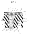
- the stud unit will be explained with reference to Fig. 4.
- each groove 32a there are grooved three grooves 32a on the outer circumferential face of the stud 32 in the axial direction thereof, so that projections or projected lines 32b are formed on the outer circumferential face of the stud 32.
- the rear end of each groove 32a is closed; the front end thereof is opened. Projected lines 32b are formed between the grooves 32a.
- the rear end section of the stud 32 has a stopper section 20.
- the radius of the stopper section 20 is slightly larger than the radius of the projected lines 32b.
- a small-diameter-cylinder section 12A which has an uneven section 13 on the inner wall thereof.
- the uneven section 13 corresponds to an uneven section 33 of the stud 32.
- the rear section of the cylinder 12 is a large-diameter-cylinder section 12B.
- a spring 30 as an elastic member between the rear end face of the stopper section 20 of the stud 32 and the bottom face 12b of the cylinder 12 so as to blase the stud 32 outward.
- the stud units 10 are, as described above, fitted in the treads 11d of the tire 11 but the tip 24 and the front end section of each stud 32 are projected from the tread 11d. Note that, only the tip 24 of the stud 32 may be projected therefrom.
- the front end of the studs 32 contact a surface of a road with the tread 11d in order.
- the weight of the vehicle works on the stud 32 contacting the road.
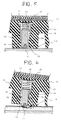
- the stud 32 contacting the road is pushed into the cylinder 12 against the elasticity of the spring 30 by the weight of the vehicle (see Fig. 5).
- the stud 32 is biased outward by the elasticity of the spring 30 but the elasticity thereof is so small that the stud 32 does not damage the road.
- the tire 11 does not slip even on the snow- or ice-covered road.
- the front end of the stud 32 contacting slightly bites the snow or ice surface because the stud 32 is biassed outward by the spring 30. Therefore, the stud 32 can keep the frictional force even if the treads 11d of the tire 11 slip when the brake is applied.
- Imaged force working to the front end of one of the studs 32 in the counter direction of “S” is defined as "f" here. If the force “f” works to the front end of the stud 32, the stud 32 inclines in the couter direction of "S” and the uneven section 33 on the outer circumferential face of the stud 32 engages with the front fringe 12a as an engage section of the uneven section 13 on the inner face of the cylinder 12.
- the spring 30 partially transforms with inclination of the stud 32. With this transformation, the stud 32 is kept projecting even the weight of the vehicle works to the stud 32 downward. Note that, as described above, the front end of the stud 32, which is biased by the spring 30, slightly bites the surface of the snow- or ice-covered road, so that the studs 32 secure the braking action of the tire 11 (see Fig. 6).
- the speed of the tire 11 is reduced upon braking.
- the tire 11 slips on the road then, the force "f" working to the studs 32 contacting the road also reduces, so that the treads 11d hold the surface of the snow- or ice-covered road at low speed and the slip is prevented.
- the projected length of the studs 32 contacting the road are respectively different because of the variation of the force "f" working.
- the torque of the tire 11 works to the road and the vehicle moves forward. If the tire 11 slips, the force "f" in the forward direction (counter direction of stopping) works to a part of the tire 11, so that the stud 32 engages with the fringe 12a of the cylinder 12, and the stud 32 is kept projecting to secure the frictional force. Therefore, the slip of the tire 11 can be prevented.
- the stud 32 inclines and the uneven section lines 33 on the outer circumferential face of the stud 32 engage with the uneven section 13 on the inner face of the cylinder 12 to keep the stud 32 projecting when the force "f" works to the front end of the stud 32. Further, the uneven section 33 of the stud 32 engages with the fringe 12a as the engage section of the uneven section 13 of the cylinder 12.
- Fig. 7 illustrates that the transverse sectional shape of the tip 24 at the front end of the stud 32 may be formed as a triangle shape.
- the stud unit 10 has a mouth piece 12g, which is made of material harder than the material of the cylinder 12, at the fringe 12a of the cylinder 12.
- the stopper section 20 for engaging with the step 16 of the cylinder 12 may be projected inward and all round.
- Fig. 9 shows a longitudinal sectional view of the stud 32 of the stud unit 10.
- the engage-step 33a engages with the fringe 12a of the cylinder 12 when the stud 32 inclines.
- the engage-step 33a may be formed on the projected lines 32b or the grooves 32a.
- Fig. 10 and 11 show that the stud unit 10 has projections 12f, which support both sides of a projected line 32b of the stud 32, at the step of the cylinder 12. Both side faces of the projected line 32b do not contact the uneven section 13 of the cylinder 12, so that the stud 32 can be moved smoothly.
- the number of the projected lines 32b of the stud 32 and the grooves on the inner face of the small-diameter-cylinder section 12A are not limited.
- Fig. 12 shows that a stud 32 may have many projected lines.
- Fig. 13 shows a sectional view of a stud according to another embodiment.
- the projected line 32b on the outer circumferential face is formed until midway thereof, not until the lower end.
- the projected line 32b of the stud 132 may be formed at least a section corresponding to a sliding section of the small-diameter-cylinder section 12A.
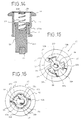
- Fig. 14 shows a sectional view of another stud unit 10.
- a hole 232a is bored in the axial direction of the stud 232 at the rear end thereof.
- the front end of the spring 30 is inserted into the hole 232a; the rear end of the spring 30 is fitted to a projected section 12d, which is projected inward on the bottomface 12b of the cylinder 12, so as not to move.
- Fig. 15 shows how both edges of the projected line 12e of the small-diameter-cylinder section 12A may be formed at an acute angle as sharp edges 12h so as to support the base section of the projected line 32b of the stud 32.
- the front ends of the sharp edges 12h engage with the uneven section 33 of the stud 32 to keep the stud projecting.
- Fig. 16 shows a bottom view of a stud unit according to another embodiment.
- Four narrow grooves 32c are grooved in the axial direction of the stud 32 on the outer circumferential face thereof;
- four projected lines 12i whose ridges are sharply formed so as to fit in the grooves 32c of the stud 32, are provided on the inner face of the small-diameter-cylinder section 12A of the cylinder 12.
- the edge of the projected lines 12i on the fringe 12a side are engaged with the stud 32 so as to prevent the stud 32 from retracting into the cylinder 12 when the stud 32 inclines.
- Fig. 17 shows a different form of grooves 32c of the stud 32 and projected lines 12i on the inner face of the cylinder 12, in which there are two or more (cf. Fig 16) .
- Figs. 18-20 show different forms of ridges of the sharp projected lines 12i for the cylinder 12. Here they are sharply formed as the examples of Figs. 16 and 17.
- Fig. 21 illustrates another form of the projected lines.
- the two ridges of each projected line 32d are sharply formed.
- the projected lines 32d engages with the fringe 12a so as to prevent the stud 32 from retracting into the cylinder 12 because of sharp ridges of the projected lines 32d of the stud 32.
- Fig. 22 illustrates another form of the projected lines for the stud unit 10.
- the stud 32 is inserted into the cylinder 12 with play.
- the largest outer diameter of the stud 32 is smaller than the smallest inner diameter of the small-diameter-cylinder section 12A, so that the stud 32 has much play. With this much play, uneven sections of the both are mutually engaged and the uneven section of the stud 32 engages with the fringe 12a of the cylinder 12 when the stud quitely inclines.
- the cylinder and the stud may be made of ceramics or plastics.
- the elastic member need be not only a spring but could be rubber, etc.
- grooved slits may be provided in the axial direction of the cylinder on the outer circumferential face thereof so as to reduce the weight of the stud unit.
Landscapes
- Engineering & Computer Science (AREA)
- Mechanical Engineering (AREA)
- Tires In General (AREA)
Claims (7)
- Unité de clou (10) prévu pour l'adaptation dans un trou percé dans une face circonférentielle extérieure d'un bandage (11), ladite unité (10) comprenant :
un cylindre (12) ayant une extrémité arrière fermé (12b) et une extrémité avant ouverte (12a) et une section de mise en prise (16) sur sa paroi circonférentielle intérieure, une pluralité de saillies (12e) s'étendant axialement étant réalisée sur la paroi intérieure du cylindre (12) à mi-distance le long du cylindre (12) vers son extrémité avant ouverte (12a) et à des intervalles réguliers dans la direction circonférentielles du cylindre ;
un clou (32) situé dans ledit cylindre (12) de façon à être déplaçable axialement dans celui-ci avec un certain jeu, ledit clou (32) ayant une extrémité avant (24) et une section d'arrêt (20) à son extrémité arrière pour coopérer avec la section de mise en prise (16) du cylindre (12) de façon à empêcher une libération du chou (32) à travers l'extrémité ouverte (12a) du cylindre (12) ; et
un moyen élastique (30) agissant entre l'extrémité arrière fermée (12b) du cylindre (12) et la section d'arrêt (20) du chou (32) pour solliciter la section d'arrêt (20) du chou (32) de telle sorte que l'extrémité avant (24) du chou (30) fait saillie depuis l'extrémité avant ouverte (12a) du cylindre (12) ;
caractérisée en ce que le clou (32) a des saillies (32b) s'étendant axialement sur sa paroi circonférentielle extérieure qui sont situées entre les saillies du cylindre (12) avec un certain jeu et en ce que le cylindre a des saillies (12f) à la section de mise en prise (16) qui supportent chaque côté des saillies de chou (32b). - Unité de clou (10) selon la revendication 1, dans laquelle les saillies (12e) sur la paroi intérieure du cylindre (12) diminuent en section transversale.
- Unité de clou selon la revendication 1 ou 2, dans laquelle les saillies (32b) sur la face circonférentielle extérieure du clou (32) diminuent en section transversale.
- Unité de clou selon l'une des revendications précédentes, comprenant en outre une embouchure (12g) réalisée en un matériau dur prévu à l'extrémité avant (12a) du cylindre (12).
- Unité de clou selon l'une des revendications précédentes, comprenant en outre une pointe dure prévue à l'extrémité avant (24) du clou (32).
- Unité de clou selon la revendication 5, dans laquelle la pointe du clou (32) est triangulaire en section transversale.
- Bandage pneumatique anti-dérapant pourvu d'unités de clou (10) telles que revendiquées dans l'une quelconque des revendications précédentes.
Applications Claiming Priority (3)
| Application Number | Priority Date | Filing Date | Title |
|---|---|---|---|
| JP144275/89 | 1989-02-23 | ||
| JP4427589 | 1989-02-23 | ||
| PCT/JP1990/000217 WO1990009899A1 (fr) | 1989-02-23 | 1990-02-22 | Unite de clou antiderapant et pneu antiderapant l'utilisant |
Publications (3)
| Publication Number | Publication Date |
|---|---|
| EP0412170A1 EP0412170A1 (fr) | 1991-02-13 |
| EP0412170A4 EP0412170A4 (en) | 1991-04-24 |
| EP0412170B1 true EP0412170B1 (fr) | 1995-11-02 |
Family
ID=12686959
Family Applications (1)
| Application Number | Title | Priority Date | Filing Date |
|---|---|---|---|
| EP90903425A Expired - Lifetime EP0412170B1 (fr) | 1989-02-23 | 1990-02-22 | Unite de clou antiderapant et pneu antiderapant l'utilisant |
Country Status (6)
| Country | Link |
|---|---|
| US (1) | US5198048A (fr) |
| EP (1) | EP0412170B1 (fr) |
| AT (1) | ATE129669T1 (fr) |
| CA (1) | CA2027563A1 (fr) |
| DE (1) | DE69023293T2 (fr) |
| WO (1) | WO1990009899A1 (fr) |
Families Citing this family (15)
| Publication number | Priority date | Publication date | Assignee | Title |
|---|---|---|---|---|
| WO2003082555A1 (fr) * | 2002-03-29 | 2003-10-09 | Pirelli Pneumatici S.P.A. | Procede de fabrication d'un pneu cloute |
| FI20045363A7 (fi) * | 2004-09-29 | 2006-03-30 | Scason Oy | Nastarenkaan nasta |
| JP4862043B2 (ja) * | 2006-05-26 | 2012-01-25 | 三菱電機株式会社 | 電動パワーステアリング装置 |
| US8082961B2 (en) * | 2007-12-31 | 2011-12-27 | The Goodyear Tire & Rubber Company | Tire with retractable stud |
| NO330285B1 (no) | 2009-05-05 | 2011-03-21 | Hans Husevag | Pigg til dekk |
| US8186985B2 (en) * | 2009-12-17 | 2012-05-29 | The Goodyear Tire & Rubber Company | Mold apparatus for forming grooves in tire shoulder |
| US20130000807A1 (en) * | 2011-06-28 | 2013-01-03 | Frederic Michel-Jean Pons | Anti-skid stud for insertion into the tread of a vehicle tire and pneumatic tire comprising such anti-skid studs |
| US9895936B2 (en) | 2011-08-25 | 2018-02-20 | Henry J. Reedy | Dynamic traction cleated tires |
| US20130048168A1 (en) * | 2011-08-25 | 2013-02-28 | Henry J. Reedy | Dynamic traction cleated tires |
| US9278584B2 (en) | 2011-10-31 | 2016-03-08 | Innovative Technologies, Llc | All-weather tire |
| US9290057B2 (en) | 2011-10-31 | 2016-03-22 | Innovative Technologies, Llc | All season safety tire |
| JP6320893B2 (ja) * | 2014-10-10 | 2018-05-09 | 東洋ゴム工業株式会社 | スタッドピン及びスタッドタイヤ |
| RU169271U1 (ru) * | 2016-08-26 | 2017-03-13 | Акционерное общество "КОРДИАНТ" | Шип противоскольжения |
| EP3578391B1 (fr) | 2018-06-08 | 2021-03-31 | Nokian Renkaat Oyj | Procédé de fabrication d'un trou borgne dans un pneu et procédé d'insertion d'un insert dans le trou borgne |
| US11084331B2 (en) | 2018-12-18 | 2021-08-10 | The Goodyear Tire & Rubber Company | Winter tire stud |
Family Cites Families (8)
| Publication number | Priority date | Publication date | Assignee | Title |
|---|---|---|---|---|
| US3583462A (en) * | 1969-05-13 | 1971-06-08 | Vincent A Langelo | Anti-skid tire apparatus |
| DE2204074A1 (de) * | 1972-01-28 | 1973-08-02 | Karlheinz Dorr | Gleitschutzkoerper fuer fahrzeugluftreifen |
| DE2337587A1 (de) * | 1973-07-24 | 1975-02-13 | Ernst Peter Steger | Spike mit federnd nach aussen gedruecktem kopf |
| DE3274531D1 (en) * | 1982-05-21 | 1987-01-15 | Stahlgruber Gruber & Co Otto | Spike for tyres |
| JPS59186704A (ja) * | 1983-04-08 | 1984-10-23 | Hiroo Hojo | 防滑タイヤ |
| JPS61268506A (ja) * | 1985-05-23 | 1986-11-28 | Bridgestone Corp | タイヤ用スパイクピン |
| FI77186C (fi) * | 1986-11-20 | 1989-02-10 | Airam Ab Oy | Slirskydd foer fordonsdaeck. |
| FI78423C (fi) * | 1987-02-27 | 1989-08-10 | Neste Oy | Holkdubb anordnad i ett fordonsdaeck. |
-
1990
- 1990-02-22 US US07/596,135 patent/US5198048A/en not_active Expired - Fee Related
- 1990-02-22 DE DE69023293T patent/DE69023293T2/de not_active Expired - Fee Related
- 1990-02-22 EP EP90903425A patent/EP0412170B1/fr not_active Expired - Lifetime
- 1990-02-22 WO PCT/JP1990/000217 patent/WO1990009899A1/fr not_active Ceased
- 1990-02-22 CA CA002027563A patent/CA2027563A1/fr not_active Abandoned
- 1990-02-22 AT AT90903425T patent/ATE129669T1/de not_active IP Right Cessation
Also Published As
| Publication number | Publication date |
|---|---|
| EP0412170A4 (en) | 1991-04-24 |
| ATE129669T1 (de) | 1995-11-15 |
| EP0412170A1 (fr) | 1991-02-13 |
| DE69023293D1 (de) | 1995-12-07 |
| WO1990009899A1 (fr) | 1990-09-07 |
| US5198048A (en) | 1993-03-30 |
| DE69023293T2 (de) | 1996-05-02 |
| CA2027563A1 (fr) | 1990-08-24 |
Similar Documents
| Publication | Publication Date | Title |
|---|---|---|
| EP0412170B1 (fr) | Unite de clou antiderapant et pneu antiderapant l'utilisant | |
| US5221379A (en) | Retractable tire stud | |
| US5198049A (en) | Stud unit and skid-proof tire having the same | |
| JPH02290703A (ja) | 防滑ピンユニットおよびこれを用いた防滑タイヤ | |
| JPH0332482B2 (fr) | ||
| US3583462A (en) | Anti-skid tire apparatus | |
| JPH01226408A (ja) | スパイクタイヤ | |
| US5785782A (en) | Slip-preventing vehicle tire | |
| JPS6127709A (ja) | 自動車タイヤ用のスパイクピン | |
| JPH0671210U (ja) | 自動車用冬用タイヤ | |
| JPH0367883B2 (fr) | ||
| JPH0332485B2 (fr) | ||
| JP4277944B2 (ja) | タイヤのスタッド構造 | |
| JPH0367882B2 (fr) | ||
| JPH02141314A (ja) | ボーゲンタイヤとマクロチェーン | |
| CN85205698U (zh) | 钉式轮胎的销钉 | |
| JP3198476B2 (ja) | 冬期用タイヤ及び冬期におけるタイヤのスリップ防止方法 | |
| JPH07257115A (ja) | トレッドと連動するスパイクを有するタイヤ | |
| KR100286420B1 (ko) | 튜브레스 타이어의 스노우 스파이크장치 | |
| JP2533450B2 (ja) | 車輪滑り止め装置 | |
| JPS63227405A (ja) | スパイクタイヤ | |
| JPS59176106A (ja) | タイヤ用スパイクピン | |
| JP2547532Y2 (ja) | スパイクタイヤの構造 | |
| JPH0466307A (ja) | 冬期間の自動車用タイヤとホイールの組合せ | |
| JPS63188506A (ja) | タイヤスリツプ防止爪 |
Legal Events
| Date | Code | Title | Description |
|---|---|---|---|
| PUAI | Public reference made under article 153(3) epc to a published international application that has entered the european phase |
Free format text: ORIGINAL CODE: 0009012 |
|
| AK | Designated contracting states |
Kind code of ref document: A1 Designated state(s): AT BE CH DE DK FR GB IT LI SE |
|
| 17P | Request for examination filed |
Effective date: 19901228 |
|
| A4 | Supplementary search report drawn up and despatched |
Effective date: 19910307 |
|
| AK | Designated contracting states |
Kind code of ref document: A4 Designated state(s): AT BE CH DE DK FR GB IT LI SE |
|
| 17Q | First examination report despatched |
Effective date: 19921007 |
|
| GRAA | (expected) grant |
Free format text: ORIGINAL CODE: 0009210 |
|
| RBV | Designated contracting states (corrected) |
Designated state(s): AT CH DE GB LI |
|
| AK | Designated contracting states |
Kind code of ref document: B1 Designated state(s): AT CH DE GB LI |
|
| REF | Corresponds to: |
Ref document number: 129669 Country of ref document: AT Date of ref document: 19951115 Kind code of ref document: T |
|
| REG | Reference to a national code |
Ref country code: CH Ref legal event code: NV Representative=s name: AMMANN PATENTANWAELTE AG BERN |
|
| REF | Corresponds to: |
Ref document number: 69023293 Country of ref document: DE Date of ref document: 19951207 |
|
| PGFP | Annual fee paid to national office [announced via postgrant information from national office to epo] |
Ref country code: AT Payment date: 19960205 Year of fee payment: 7 |
|
| PGFP | Annual fee paid to national office [announced via postgrant information from national office to epo] |
Ref country code: GB Payment date: 19960212 Year of fee payment: 7 |
|
| PGFP | Annual fee paid to national office [announced via postgrant information from national office to epo] |
Ref country code: CH Payment date: 19960304 Year of fee payment: 7 |
|
| PLBE | No opposition filed within time limit |
Free format text: ORIGINAL CODE: 0009261 |
|
| STAA | Information on the status of an ep patent application or granted ep patent |
Free format text: STATUS: NO OPPOSITION FILED WITHIN TIME LIMIT |
|
| 26N | No opposition filed | ||
| PG25 | Lapsed in a contracting state [announced via postgrant information from national office to epo] |
Ref country code: GB Effective date: 19970222 Ref country code: AT Effective date: 19970222 |
|
| PGFP | Annual fee paid to national office [announced via postgrant information from national office to epo] |
Ref country code: DE Payment date: 19970227 Year of fee payment: 8 |
|
| PG25 | Lapsed in a contracting state [announced via postgrant information from national office to epo] |
Ref country code: LI Effective date: 19970228 Ref country code: CH Effective date: 19970228 |
|
| GBPC | Gb: european patent ceased through non-payment of renewal fee |
Effective date: 19970222 |
|
| REG | Reference to a national code |
Ref country code: CH Ref legal event code: PL |
|
| PG25 | Lapsed in a contracting state [announced via postgrant information from national office to epo] |
Ref country code: DE Free format text: LAPSE BECAUSE OF NON-PAYMENT OF DUE FEES Effective date: 19981103 |