EP0413355B1 - Circuit d'amplification de puissance pour véhicule pour émetteur-récepteur portable à niveaux multiples - Google Patents
Circuit d'amplification de puissance pour véhicule pour émetteur-récepteur portable à niveaux multiples Download PDFInfo
- Publication number
- EP0413355B1 EP0413355B1 EP90115809A EP90115809A EP0413355B1 EP 0413355 B1 EP0413355 B1 EP 0413355B1 EP 90115809 A EP90115809 A EP 90115809A EP 90115809 A EP90115809 A EP 90115809A EP 0413355 B1 EP0413355 B1 EP 0413355B1
- Authority
- EP
- European Patent Office
- Prior art keywords
- power
- voltage
- transceiver
- transmit signal
- gain
- Prior art date
- Legal status (The legal status is an assumption and is not a legal conclusion. Google has not performed a legal analysis and makes no representation as to the accuracy of the status listed.)
- Expired - Lifetime
Links
- 230000008878 coupling Effects 0.000 description 2
- 238000010168 coupling process Methods 0.000 description 2
- 238000005859 coupling reaction Methods 0.000 description 2
- 238000010586 diagram Methods 0.000 description 2
- 230000009365 direct transmission Effects 0.000 description 2
- 230000004048 modification Effects 0.000 description 2
- 238000012986 modification Methods 0.000 description 2
- 230000005540 biological transmission Effects 0.000 description 1
- 238000013479 data entry Methods 0.000 description 1
- 238000001514 detection method Methods 0.000 description 1
- 230000000694 effects Effects 0.000 description 1
- 238000009499 grossing Methods 0.000 description 1
- 238000010295 mobile communication Methods 0.000 description 1
- 239000003381 stabilizer Substances 0.000 description 1
- 230000000087 stabilizing effect Effects 0.000 description 1
Images

Classifications
-
- H—ELECTRICITY
- H04—ELECTRIC COMMUNICATION TECHNIQUE
- H04B—TRANSMISSION
- H04B1/00—Details of transmission systems, not covered by a single one of groups H04B3/00 - H04B13/00; Details of transmission systems not characterised by the medium used for transmission
- H04B1/38—Transceivers, i.e. devices in which transmitter and receiver form a structural unit and in which at least one part is used for functions of transmitting and receiving
- H04B1/3827—Portable transceivers
- H04B1/3877—Arrangements for enabling portable transceivers to be used in a fixed position, e.g. cradles or boosters
Definitions
- the present invention relates generally to mobile communications system, and more specifically to vehicular power booster circuitry for a duplex multi-level portable radio transceiver.
- a mobile radio transceiver as shown and described in US-A-4,636,741 comprises a portable radio transceiver and a vehicular adaptor having an antenna.
- the portable transceiver When the portable transceiver is used in the vehicle, it is coupled to the adaptor to enable it to amplify the signal from the transceiver and transmit it from the antenna of the adaptor, instead of from the antenna of the transceiver.
- the transceiver When the transceiver is used outside of the vehicle, it is disconnected from the adaptor and operates on a built-in battery to transmit signals from the transceiver antenna.
- Power control driver is provided in the transceiver unit to set its output power at one of predetermined power levels.
- the transceiver When the transceiver is operated on the adaptor mode for boosting power, the power level established in the transceiver is communicated to the adaptor in the form of an encoded signal. Therefore, the adaptor must be provided with a decoding circuit to receive the power level identification code to set the booster power level corresponding to the level set by the transceiver. Since the prior art transceiver has an antenna of its own and can generate sufficient power for direct transmission from the antenna, it can be used with a high degree of freedom outside of the vehicle. However, the circuitry for generating the necessary power for direct transmission from the transceiver occupies an extra space and adds to its weight. It may be desirable that the transceiver be less bulky and unwieldy for use inside of the vehicle if there is no need to use it outside of the vehicle with such a high degree of freedom as that of the prior art.
- a mobile radio transceiver as described comprises a portable transceiver and a vehicular power booster.
- the portable transceiver generates a radio-frequency transmit signal and sets the power of the signal at one of predetermined power levels.
- the vehicular power booster is coupled by a connecting cable to the portable transceiver to receive the RF transmit signal, and includes a first power detector for detecting the power of the RF transmit signal from the portable transceiver.
- a reference voltage source is provided for generating a set of reference voltages respectively representing the predetermined power levels.
- a decision circuit is provided for identifying one of the reference voltages as corresponding to the power detected by the first power detector.
- a variable-gain controlled power amplifier stage amplifies the RF transmit signal and applies it to a vehicle antenna.
- a second power detector detects the power of the power-amplified RF signal.
- a gain control driver is responsive to a difference between the power detected by the second power detector and the identified reference voltage for controlling the gain of the power amplifier stage so that the difference
- the vehicular power booster comprises a first variable-gain controlled amplifier stage for amplifying the RF transmit siqnal received from the transceiver.
- a first detector is connected to the output of the amplifier to detect an average voltage of the amplified RF transmit signal.
- a first gain control driver is responsive to a first difference between the detected average voltage and a preselected reference voltage for generating a gain control voltage and applying it to the first amplifier stage so that the first difference reduces to a minimum.
- a reference voltage source generates multiple reference voltages respectively representing the predetermined power levels of the transceiver. Since the gain control voltage is variable with the power setting of the portable transceiver, a decision circuit uses this power setting to determine which one of the reference voltages the transceiver's power setting corresponds to.
- a second, variable-gain controlled, class C power amplifier stage is provided for further amplifying the output of the first amplifier stage for application to a vehicle antenna.
- a power detector is connected to the output of the second amplifier stage.
- a second gain control driver is responsive to a second difference between the detected power and the identified reference voltage for controlling the gain of the second amplifier stage so that the second difference substantially reduces to a minimum.
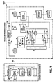
- the radio transceiver comprises a hand-held portable transceiver unit 10 and a vehicular power booster unit 20 which is permanently mounted in a vehicle and coupled by a connecting cable 18 to the portable transceiver unit Connecting cable 18 has a sufficient length to allow users to go out of the vehicle while carrying the hand-held unit 10.
- Transceiver 10 comprises a radio-frequency (RF) transmitter 11 which amplifies signals from a microphone 14, modulates it upon a radio-frequency carrier and amplifies the modulated carrier by a power amplifying stage for coupling through connecting cable 18 to power booster 20.
- RF radio-frequency
- the gain of the power amplifying stage of transmitter 11 is controlled by a controller 12 so that the power of radio-frequency transmit signal is set at one of predetermined power setting levels.
- the difference between adjacent transmit power levels of the booster is specified as 4 dB, but it is sufficient to ensure a 2-dB difference between adjacent power levels at the output of transceiver 11.
- a keypad 16 is connected for dialing, power control and numeric data entry purposes.
- a radio-frequency receiver 13 is also coupled through connecting cable 18 to power booster 20 to receive RF receive signal from power booster 20 for reproduction by a speaker 15. All active modules of the portable unit 10 are powered by a battery 17 provided therein.
- Vehicular power booster 20 includes a transmit filter 21 that separates the RF transmit signal from transmitter 11 from the RF receive signal and applies the separated transmit signal to a variable-gain controlled power amplifier stage 22, which amplifies the RF transmit signal with a variable gain which is controlled by a gain control driver 27.
- the amplified RF transmit signal from is passed through a transmit filter 23 to an antenna 34 for transmission to a station that is connected to a public switched telephone network.
- a power detector 30 To the output of transmit filter 21 is connected a power detector 30.
- This detector comprises a rectifier 30a and an integrator 30b, and applies an average voltage representative of the power of the RF transmit signal to comparators 25-1 to 25-N.
- a reference voltage source 24 is provided for generating N reference voltages respectively representing the predetermined power levels established by the transceiver unit 10. The reference voltages are respectively applied to comparators 25-1 to 25-N in which the power-representative voltage from detector 30 is compared with each reference voltage to identify one of the reference voltages as corresponding to the detected power.
- the outputs of comparators 25-1 to 25-N are connected respectively to control inputs of switches 26-1 to 26-N to allow the identified reference voltage to be passed to a first control input of gain control driver 27.
- a power detector 28 of the same circuitry as power detector 30 is connected to the output of power amplifier stage 22 to supply a voltage representative of the power of the power-amplified RF transmit signal to a second control input of gain control driver 27.
- Gain control driver 27 controls the gain of power amplifier stage 22 in a negative feedback loop so that the difference between the reference voltage identified by one of the comparators 25 and the power detected by power detector 28 reduces to a minimum. In this way, the output power of amplifier stage 22 is automatically adjusted to an amplified version of the power level originally set by transceiver 10.
- Vehicular power booster 20 further includes a receive filter 31 coupled to antenna 34 to separate the RF receive signal from the RF transmit signal.
- the output of filter 31 is amplified by a preamplifier stage 32 and passed through another receive filter 33 and connecting cable 18 to receiver 13. All active modules of the power booster are powered from a voltage stabilizer 35 coupled to a vehicle battery 36. Therefore, the power drain units of the mobile radio transceiver are separated from the portable unit 10 to make it lightweight and easy to handle with a smallest possible number of lines bundled into the connecting cable 18.
- portable unit 10 and power booster 20 can be implemented without the requirement of complex coding and decoding circuitry.
- power amplifier stage 22 is implemented with a class C amplifier, it is desirable that the input level of the amplifier is maintained constant regardless of the power level setting of transceiver 10. In addition, when cable 18 is extended to fullest length it is desirable to minimize effects caused by noise which is introduced to cable 18 by electromagnetic coupling from the vehicle engine.
- a class C power amplifier stage 22a is used and a gain-controlled voltage amplifier stage 40 is provided between the filter 21 and power amplifier stage 22a to amplify the voltage level of the RF transmit signal.
- a voltage detector 41 of the same circuitry as power detector 30 of Fig. 1 is connected to the output of voltage amplifier stage 40 to generate a signal representative of an average voltage of the voltage-amplified RF transmit signal.
- a gain control driver 42 is provided to produce a gain control voltage that controls the gain of voltage amplifier 40 in a negative feedback mode in response to a difference between the output of voltage detector 41 and a preselected reference voltage supplied from a voltage source 24a. In this way, the difference reduces to a minimum and the output voltage of amplifier 40 is maintained constant at a level appropriate for the operation of power amplifier stage 22a.
- the gain control voltage of the driver 42 is inversely variable with the power setting of transceiver 10, it is applied to comparators 25-1 to 25-N for comparison with reference voltages generated by voltage source 24a.
- One of the comparators 25 will produce an output to indicate that the corresponding reference voltage as corresponding to the transceiver's power setting and to operate the associated switching gate 26.
- a second reference voltage source 29 is provided for generating a set of second reference voltages which are appropriately established for the operation of gain control driver 27, but correspond respectively to those generated by voltage source 24a.
- the second reference voltages are supplied to switching gates 26-1 to 26-N.
- One of these voltages is passed through the operated switching gate to gain control driver 27 to permit it to drive the class C amplifier stage 22a in a negative feedback mode so that the difference between the reference voltage and the output of power detector 28 reduces to a minimum.
- the output of power amplifier 22a corresponds to the power setting of transceiver 10.
- the negative feedback operation by voltage detector 41 and gain control driver 42 performs a smoothing action on the noise, stabilizing the booster's output power level.
Landscapes
- Engineering & Computer Science (AREA)
- Computer Networks & Wireless Communication (AREA)
- Signal Processing (AREA)
- Transmitters (AREA)
- Transceivers (AREA)
Claims (5)
- Emetteur-récepteur radio mobile comprenant :un émetteur-récepteur portable (10) comprenant un émetteur (11) pour générer un signal d'émission de radiofréquences (RF), des moyens de réglage manuels (16) de la puissance pour régler ledit signal d'émission à l'un des niveaux de puissance prédéterminés et un récepteur (13) pour recevoir un signal de réception RF ; etun circuit d'amplification pour véhicule (20) couplé par un câble de connexion (18) audit émetteur-récepteur portable pour recevoir ledit signal d'émission RF, caractérisé en ce que le circuit d'amplification (20) comprend :des moyens formant détecteur de tension (30 ; 41) pour détecter une tension représentative de la puissance du signal d'émission RF reçue à partir de l'émetteur-récepteur portable (10) ;une source de tension de référence (24) pour générer des tensions de référence représentant respectivement lesdits niveaux de puissance prédéterminés ;des moyens de décision (25-1 à 25-N, 26-1 à 26-N) pour identifier l'une desdites tensions de référence comme correspondant à la tension détectée par lesdits moyens formant détecteur de tension (30 ; 41) ;un amplificateur de puissance à gain commandé (22 ; 22a) pour amplifier ledit signal d'émission RF et appliquer le signal d'émission RF à puissance amplifiée à une antenne ;des moyens formant détecteur de puissance (28) couplés à la sortie dudit amplificateur de puissance (22 ; 22a) pour détecter la puissance dudit signal d'émission RF à puissance amplifiée ; etdes moyens de commande de gain (27) sensibles à une différence entre une tension représentative du signal d'émission RF à puissance amplifiée et ladite tension de référence identifiée (figure 1) ou une tension en rapport à ladite tension de référence identifiée mais délivrée par une source de tension distincte (29) (figure 2) pour commander le gain dudit amplificateur de puissance (22, 22a) de telle sorte que ladite puissance détectée corresponde au réglage de puissance dudit émetteur-récepteur portable.
- Emetteur-récepteur radio mobile selon la revendication 1, dans lequel lesdits moyens de décision (25) comprennent :des moyens formant comparateur (25-1 à 25-N) pour comparer ladite puissance de sortie détectée avec lesdites tensions de référence ; etdes moyens formant sélecteur (26-1 à 25-N) pour sélectionner l'une desdites tensions de référence en réponse à la sortie desdits moyens formant comparateur (25-1 à 25-N) et appliquer la tension de référence sélectionnée auxdits moyens de commande de gain (27) en tant que dite tension de référence identifiée.
- Emetteur-récepteur radio mobile selon la revendication 1, dans lequel ledit émetteur-récepteur portable est alimenté par une batterie prévue dans ledit émetteur-récepteur portable, et ledit circuit d'amplificateur de puissance pour véhicule est alimenté par une batterie de véhicule.
- Emetteur-récepteur radio mobile selon la revendication 1 ou 2, dans lequel ledit circuit amplificateur de puissance (20) pour véhicule comprend en outre un étage préamplificateur pour amplifier un signal de réception RF détecté par ladite antenne et appliquer les signaux de réception amplifiés audit émetteur-récepteur portable au moyen dudit câble de connexion.
- Emetteur-récepteur radio mobile selon l'une quelconque des revendications 1 à 4, comprenant :un second amplificateur à gain commandé (40) pour amplifier le signal d'émission RF reçu à partir dudit émetteur-récepteur portable (10) ;ledit détecteur de tension (41) étant couplé au second amplificateur à gain commandé (40) pour détecter une tension moyenne du signal d'émission RF amplifié ;ledit émetteur-récepteur radio mobile comprenant en outre des seconds moyens de commande de gain (42) sensibles à la différence entre la tension moyenne détectée et une tension de référence pour commander le gain du second amplificateur à gain commandé (40) de telle sorte que ladite tension moyenne détectée soit maintenue à une valeur constante ; dans lequel le premier amplificateur à gain commandé est un amplificateur de puissance de classe C (22a).
Applications Claiming Priority (2)
| Application Number | Priority Date | Filing Date | Title |
|---|---|---|---|
| JP1212334A JPH0775324B2 (ja) | 1989-08-18 | 1989-08-18 | 携帯無線機 |
| JP212334/89 | 1989-08-18 |
Publications (3)
| Publication Number | Publication Date |
|---|---|
| EP0413355A2 EP0413355A2 (fr) | 1991-02-20 |
| EP0413355A3 EP0413355A3 (en) | 1992-11-25 |
| EP0413355B1 true EP0413355B1 (fr) | 1997-07-16 |
Family
ID=16620820
Family Applications (1)
| Application Number | Title | Priority Date | Filing Date |
|---|---|---|---|
| EP90115809A Expired - Lifetime EP0413355B1 (fr) | 1989-08-18 | 1990-08-17 | Circuit d'amplification de puissance pour véhicule pour émetteur-récepteur portable à niveaux multiples |
Country Status (4)
| Country | Link |
|---|---|
| US (1) | US5193219A (fr) |
| EP (1) | EP0413355B1 (fr) |
| JP (1) | JPH0775324B2 (fr) |
| DE (1) | DE69031059T2 (fr) |
Families Citing this family (35)
| Publication number | Priority date | Publication date | Assignee | Title |
|---|---|---|---|---|
| JPH03109829A (ja) * | 1989-09-25 | 1991-05-09 | Fujitsu Ltd | 携帯電話用車載アダプタシステム |
| FI89120C (fi) * | 1991-09-24 | 1993-08-10 | Nokia Mobile Phones Ltd | Effektinstaellning i en boosterfoerstaerkare |
| JPH0591039A (ja) * | 1991-09-30 | 1993-04-09 | Nec Corp | 携帯無線端末装置および車載無線端末装置 |
| JPH05160772A (ja) * | 1991-12-10 | 1993-06-25 | Matsushita Electric Ind Co Ltd | 携帯電話装置 |
| FI91201C (fi) * | 1992-06-05 | 1994-05-25 | Nokia Mobile Phones Ltd | Boosteri |
| US5404586A (en) * | 1992-09-29 | 1995-04-04 | Fujitsu Ltd. | Transmitter having automatic power controller |
| US5457814A (en) * | 1993-10-02 | 1995-10-10 | Nokia Mobile Phones Ltd. | Power boost system for cellular telephone |
| JPH06260996A (ja) * | 1992-10-02 | 1994-09-16 | Nokia Mobile Phones Ltd | セルラ電話用出力増幅システム |
| KR950007973B1 (ko) * | 1992-11-27 | 1995-07-21 | 삼성전자주식회사 | 휴대용 무선송수신기의 고주파 출력레벨 보상회로 |
| WO1994018761A1 (fr) * | 1993-02-05 | 1994-08-18 | Kabushiki Kaisha Toshiba | Telephone sans fil |
| JPH06276146A (ja) * | 1993-03-19 | 1994-09-30 | Fujitsu Ltd | 移動電話装置 |
| US6885845B1 (en) * | 1993-04-05 | 2005-04-26 | Ambit Corp. | Personal communication device connectivity arrangement |
| US6594471B1 (en) * | 1993-04-05 | 2003-07-15 | Ambit Corp | Radiative focal area antenna transmission coupling arrangement |
| US5711014A (en) * | 1993-04-05 | 1998-01-20 | Crowley; Robert J. | Antenna transmission coupling arrangement |
| FI99180C (fi) * | 1993-04-26 | 1997-10-10 | Nokia Mobile Phones Ltd | Menetelmä radiopuhelimen käyttämiseksi ulkoisen vahvistinlaitteen kanssa ja menetelmässä käytettävä radiopuhelin ja vahvistinlaite |
| JPH06334541A (ja) * | 1993-05-25 | 1994-12-02 | Sony Corp | 無線送信機 |
| JP2823485B2 (ja) * | 1993-07-23 | 1998-11-11 | 三菱電機株式会社 | バースト送信装置 |
| CA2135816C (fr) * | 1993-11-19 | 2000-02-15 | Takashi Enoki | Circuit de transmission a boucle de reglage du gain amelioree |
| US5570062A (en) * | 1994-10-12 | 1996-10-29 | Ericsson Ge Mobile Communications Inc. | AM-FM transmitter power amplifier using class-BC |
| US5732335A (en) * | 1995-04-28 | 1998-03-24 | Telefonaktiebolaget Lm Ericsson | Externally controlled output power by means of antenna keying |
| US6458366B1 (en) | 1995-09-01 | 2002-10-01 | Corixa Corporation | Compounds and methods for diagnosis of tuberculosis |
| US6230031B1 (en) | 1997-03-31 | 2001-05-08 | Oki Telecom, Inc. | Power amplifying circuitry for wireless radio transceivers |
| GB2329792A (en) * | 1997-08-20 | 1999-03-31 | Nokia Telecommunications Oy | Identification signals enable a transceiver module to correctly configure itself to an attached functional module |
| US6459915B2 (en) * | 1997-09-02 | 2002-10-01 | Matsushita Electric Industrial Co. Ltd. | External adapter for a portable cellular phone |
| JP3090112B2 (ja) * | 1998-01-30 | 2000-09-18 | 日本電気株式会社 | 携帯電話用ブースタ |
| JP3669497B2 (ja) * | 2001-10-29 | 2005-07-06 | 埼玉日本電気株式会社 | 送信装置、及びその自動利得制御方法 |
| US6892080B2 (en) * | 2001-11-27 | 2005-05-10 | Arrista Technologies, Inc. | Booster amplifier for cellular telephone cradles |
| US20050002677A1 (en) * | 2003-07-03 | 2005-01-06 | Polychromix, Inc. | Methods and apparatus for monitoring the strength of carriers in an optical communication system |
| US20070270111A1 (en) * | 2006-05-19 | 2007-11-22 | Broadcom Corporation | Dual power mode transmitter |
| US7860467B2 (en) * | 2006-08-29 | 2010-12-28 | Broadcom Corporation | Power control for a dual mode transmitter |
| GB2530424B (en) | 2008-11-18 | 2016-05-04 | Nujira Ltd | Power Supply Arrangement For Multi-Stage Amplifier |
| JP5979087B2 (ja) * | 2013-06-18 | 2016-08-24 | 株式会社デンソー | 車載通信装置 |
| JP7177247B2 (ja) * | 2018-08-14 | 2022-11-22 | エイブイエックス・アンテナ・インコーポレーテッド | モーダル・アンテナの制御方法およびシステム |
| US11483778B2 (en) * | 2019-07-16 | 2022-10-25 | Molex CVS Bochum GmbH | Compensator system with feedback |
| CN116367293B (zh) * | 2021-12-27 | 2026-02-10 | 成都鼎桥通信技术有限公司 | 车载终端的通信方法及设备 |
Family Cites Families (10)
| Publication number | Priority date | Publication date | Assignee | Title |
|---|---|---|---|---|
| US3648186A (en) * | 1970-03-24 | 1972-03-07 | Kahn Res Lab | Amplification system |
| US4585903A (en) * | 1982-01-25 | 1986-04-29 | Viking Phone Company | Cordless telephone |
| US4442407A (en) * | 1982-06-11 | 1984-04-10 | The United States Of America As Represented By The Secretary Of The Army | Two loop automatic level control for power amplifier |
| US4581725A (en) * | 1982-07-21 | 1986-04-08 | Mobil Oil Corporation | Method and system for gain selection |
| JPS60223231A (ja) * | 1984-04-19 | 1985-11-07 | Nec Corp | 無線通信機 |
| JPS61151421U (fr) * | 1985-03-12 | 1986-09-19 | ||
| US4636741A (en) * | 1985-11-01 | 1987-01-13 | Motorola, Inc. | Multi-level power amplifying circuitry for portable radio transceivers |
| JPS6397020A (ja) * | 1986-10-13 | 1988-04-27 | Matsushita Electric Ind Co Ltd | 送信出力の制御装置 |
| JPH01220919A (ja) * | 1988-02-29 | 1989-09-04 | Toshiba Corp | 無線電話装置 |
| JP2769478B2 (ja) * | 1989-04-10 | 1998-06-25 | 三菱電機株式会社 | 無線機 |
-
1989
- 1989-08-18 JP JP1212334A patent/JPH0775324B2/ja not_active Expired - Lifetime
-
1990
- 1990-08-17 EP EP90115809A patent/EP0413355B1/fr not_active Expired - Lifetime
- 1990-08-17 US US07/569,041 patent/US5193219A/en not_active Expired - Fee Related
- 1990-08-17 DE DE69031059T patent/DE69031059T2/de not_active Expired - Fee Related
Also Published As
| Publication number | Publication date |
|---|---|
| JPH0775324B2 (ja) | 1995-08-09 |
| DE69031059D1 (de) | 1997-08-21 |
| EP0413355A3 (en) | 1992-11-25 |
| EP0413355A2 (fr) | 1991-02-20 |
| DE69031059T2 (de) | 1997-12-04 |
| JPH0376430A (ja) | 1991-04-02 |
| US5193219A (en) | 1993-03-09 |
Similar Documents
| Publication | Publication Date | Title |
|---|---|---|
| EP0413355B1 (fr) | Circuit d'amplification de puissance pour véhicule pour émetteur-récepteur portable à niveaux multiples | |
| US6233438B1 (en) | Wide-range power control systems and methods for radio frequency transmitters and mobile radiotelephones | |
| US5170494A (en) | Two piece radio telephone | |
| US5220678A (en) | Method and apparatus for adjusting the power of a transmitter | |
| US5673001A (en) | Method and apparatus for amplifying a signal | |
| US4392245A (en) | Radio transmitter having an output power control circuit | |
| CA1315343C (fr) | Appareil de radiotelephonie | |
| JP2845130B2 (ja) | 通信装置 | |
| EP0534681B1 (fr) | Amplificateur de puissance pour un radio-téléphone | |
| US5511234A (en) | Radio-frequency output level compensating circuit of portable radio transceiver | |
| US5335369A (en) | Automatic power control circuit for use with a radio telecommunication apparatus | |
| JP2559532B2 (ja) | 携帯用電話機の車載型ブースタシステム | |
| US5305373A (en) | Cordless telephone apparatus including an antenna gain switching circuit | |
| JP3180429B2 (ja) | 移動電話装置 | |
| EP0372965B1 (fr) | Radiotéléphone en deux parties | |
| JP2568780B2 (ja) | 携帯電話装置 | |
| KR920007475B1 (ko) | 부스터를 접속한 휴대용 무선전화기 장치 | |
| JPH06112877A (ja) | 携帯無線電話装置 | |
| JP3059892B2 (ja) | パワーコントロール回路 | |
| KR100189619B1 (ko) | 주변환경 변화에 따른 자동 국선링 제어방법 | |
| JPH0481898B2 (fr) | ||
| KR0154733B1 (ko) | 셀룰라 전화기의 부스터회로 및 방법 | |
| JP2568779B2 (ja) | 携帯電話装置 | |
| JP2568778B2 (ja) | 携帯電話装置 | |
| JPH05160772A (ja) | 携帯電話装置 |
Legal Events
| Date | Code | Title | Description |
|---|---|---|---|
| PUAI | Public reference made under article 153(3) epc to a published international application that has entered the european phase |
Free format text: ORIGINAL CODE: 0009012 |
|
| 17P | Request for examination filed |
Effective date: 19900914 |
|
| AK | Designated contracting states |
Kind code of ref document: A2 Designated state(s): DE GB NL |
|
| PUAL | Search report despatched |
Free format text: ORIGINAL CODE: 0009013 |
|
| AK | Designated contracting states |
Kind code of ref document: A3 Designated state(s): DE GB NL |
|
| 17Q | First examination report despatched |
Effective date: 19941010 |
|
| GRAG | Despatch of communication of intention to grant |
Free format text: ORIGINAL CODE: EPIDOS AGRA |
|
| GRAH | Despatch of communication of intention to grant a patent |
Free format text: ORIGINAL CODE: EPIDOS IGRA |
|
| GRAH | Despatch of communication of intention to grant a patent |
Free format text: ORIGINAL CODE: EPIDOS IGRA |
|
| GRAA | (expected) grant |
Free format text: ORIGINAL CODE: 0009210 |
|
| AK | Designated contracting states |
Kind code of ref document: B1 Designated state(s): DE GB NL |
|
| REF | Corresponds to: |
Ref document number: 69031059 Country of ref document: DE Date of ref document: 19970821 |
|
| PLBE | No opposition filed within time limit |
Free format text: ORIGINAL CODE: 0009261 |
|
| STAA | Information on the status of an ep patent application or granted ep patent |
Free format text: STATUS: NO OPPOSITION FILED WITHIN TIME LIMIT |
|
| 26N | No opposition filed | ||
| PGFP | Annual fee paid to national office [announced via postgrant information from national office to epo] |
Ref country code: DE Payment date: 20000807 Year of fee payment: 11 |
|
| PGFP | Annual fee paid to national office [announced via postgrant information from national office to epo] |
Ref country code: GB Payment date: 20000816 Year of fee payment: 11 |
|
| PGFP | Annual fee paid to national office [announced via postgrant information from national office to epo] |
Ref country code: NL Payment date: 20000831 Year of fee payment: 11 |
|
| PG25 | Lapsed in a contracting state [announced via postgrant information from national office to epo] |
Ref country code: GB Free format text: LAPSE BECAUSE OF NON-PAYMENT OF DUE FEES Effective date: 20010817 |
|
| PG25 | Lapsed in a contracting state [announced via postgrant information from national office to epo] |
Ref country code: NL Free format text: LAPSE BECAUSE OF NON-PAYMENT OF DUE FEES Effective date: 20020301 |
|
| GBPC | Gb: european patent ceased through non-payment of renewal fee |
Effective date: 20010817 |
|
| NLV4 | Nl: lapsed or anulled due to non-payment of the annual fee |
Effective date: 20020301 |
|
| PG25 | Lapsed in a contracting state [announced via postgrant information from national office to epo] |
Ref country code: DE Free format text: LAPSE BECAUSE OF NON-PAYMENT OF DUE FEES Effective date: 20020501 |