EP0415508A2 - ProcÀ©dé et appareil pour le durcissement en continu de résines durcissables par la lumière - Google Patents
ProcÀ©dé et appareil pour le durcissement en continu de résines durcissables par la lumière Download PDFInfo
- Publication number
- EP0415508A2 EP0415508A2 EP90300083A EP90300083A EP0415508A2 EP 0415508 A2 EP0415508 A2 EP 0415508A2 EP 90300083 A EP90300083 A EP 90300083A EP 90300083 A EP90300083 A EP 90300083A EP 0415508 A2 EP0415508 A2 EP 0415508A2
- Authority
- EP
- European Patent Office
- Prior art keywords
- light
- curing resins
- irradiation
- flux density
- irradiated
- Prior art date
- Legal status (The legal status is an assumption and is not a legal conclusion. Google has not performed a legal analysis and makes no representation as to the accuracy of the status listed.)
- Granted
Links
Images



Classifications
-
- A—HUMAN NECESSITIES
- A61—MEDICAL OR VETERINARY SCIENCE; HYGIENE
- A61C—DENTISTRY; APPARATUS OR METHODS FOR ORAL OR DENTAL HYGIENE
- A61C19/00—Dental auxiliary appliances
- A61C19/003—Apparatus for curing resins by radiation
-
- B—PERFORMING OPERATIONS; TRANSPORTING
- B29—WORKING OF PLASTICS; WORKING OF SUBSTANCES IN A PLASTIC STATE IN GENERAL
- B29C—SHAPING OR JOINING OF PLASTICS; SHAPING OF MATERIAL IN A PLASTIC STATE, NOT OTHERWISE PROVIDED FOR; AFTER-TREATMENT OF THE SHAPED PRODUCTS, e.g. REPAIRING
- B29C35/00—Heating, cooling or curing, e.g. crosslinking or vulcanising; Apparatus therefor
- B29C35/02—Heating or curing, e.g. crosslinking or vulcanizing during moulding, e.g. in a mould
- B29C35/0277—Apparatus with continuous transport of the material to be cured
-
- B—PERFORMING OPERATIONS; TRANSPORTING
- B29—WORKING OF PLASTICS; WORKING OF SUBSTANCES IN A PLASTIC STATE IN GENERAL
- B29C—SHAPING OR JOINING OF PLASTICS; SHAPING OF MATERIAL IN A PLASTIC STATE, NOT OTHERWISE PROVIDED FOR; AFTER-TREATMENT OF THE SHAPED PRODUCTS, e.g. REPAIRING
- B29C35/00—Heating, cooling or curing, e.g. crosslinking or vulcanising; Apparatus therefor
- B29C35/02—Heating or curing, e.g. crosslinking or vulcanizing during moulding, e.g. in a mould
- B29C35/08—Heating or curing, e.g. crosslinking or vulcanizing during moulding, e.g. in a mould by wave energy or particle radiation
-
- B—PERFORMING OPERATIONS; TRANSPORTING
- B29—WORKING OF PLASTICS; WORKING OF SUBSTANCES IN A PLASTIC STATE IN GENERAL
- B29C—SHAPING OR JOINING OF PLASTICS; SHAPING OF MATERIAL IN A PLASTIC STATE, NOT OTHERWISE PROVIDED FOR; AFTER-TREATMENT OF THE SHAPED PRODUCTS, e.g. REPAIRING
- B29C35/00—Heating, cooling or curing, e.g. crosslinking or vulcanising; Apparatus therefor
- B29C35/02—Heating or curing, e.g. crosslinking or vulcanizing during moulding, e.g. in a mould
- B29C35/08—Heating or curing, e.g. crosslinking or vulcanizing during moulding, e.g. in a mould by wave energy or particle radiation
- B29C35/0805—Heating or curing, e.g. crosslinking or vulcanizing during moulding, e.g. in a mould by wave energy or particle radiation using electromagnetic radiation
- B29C2035/0822—Heating or curing, e.g. crosslinking or vulcanizing during moulding, e.g. in a mould by wave energy or particle radiation using electromagnetic radiation using IR radiation
-
- B—PERFORMING OPERATIONS; TRANSPORTING
- B29—WORKING OF PLASTICS; WORKING OF SUBSTANCES IN A PLASTIC STATE IN GENERAL
- B29C—SHAPING OR JOINING OF PLASTICS; SHAPING OF MATERIAL IN A PLASTIC STATE, NOT OTHERWISE PROVIDED FOR; AFTER-TREATMENT OF THE SHAPED PRODUCTS, e.g. REPAIRING
- B29C35/00—Heating, cooling or curing, e.g. crosslinking or vulcanising; Apparatus therefor
- B29C35/02—Heating or curing, e.g. crosslinking or vulcanizing during moulding, e.g. in a mould
- B29C35/08—Heating or curing, e.g. crosslinking or vulcanizing during moulding, e.g. in a mould by wave energy or particle radiation
- B29C35/0805—Heating or curing, e.g. crosslinking or vulcanizing during moulding, e.g. in a mould by wave energy or particle radiation using electromagnetic radiation
- B29C2035/0833—Heating or curing, e.g. crosslinking or vulcanizing during moulding, e.g. in a mould by wave energy or particle radiation using electromagnetic radiation using actinic light
-
- B—PERFORMING OPERATIONS; TRANSPORTING
- B29—WORKING OF PLASTICS; WORKING OF SUBSTANCES IN A PLASTIC STATE IN GENERAL
- B29L—INDEXING SCHEME ASSOCIATED WITH SUBCLASS B29C, RELATING TO PARTICULAR ARTICLES
- B29L2011/00—Optical elements, e.g. lenses, prisms
- B29L2011/0016—Lenses
Definitions
- the present invention relates to a method and an apparatus for continuous hardening of light-curing resins, and in particular to a method and an apparatus for continuous hardening of light-curing resins by continuously hardening the objects made of light-curing resins while they are in movement.
- the method and the apparatus for hardening the light-curing resins are divided into those using ultraviolet light and those using visible light.
- the hardening apparatus using ultraviolet light is mostly used for the hardening of the thinner objects with thickness of several ⁇ m to several hundreds of ⁇ m such as film, ink, coating film, etc. of light-curing resins.
- These apparatuses comprise the continuous moving means such as belt conveyor, and the object thinly coated with light-curing resins are continuously hardened by irradiating ultraviolet light.
- the apparatuses have high productivity and are widely used.
- the method and the apparatus using visible light are applied, for example, for the hardening of dental laboratory products using composite resin in the field of dentistry.
- the Japanese Provisional Patent Publication Sho 62-38149 describes an irradiation apparatus having fluorescent lamp to emit the visible ray of 400 - 500 nm
- the Japanese Provisional Patent Publication Sho 62-47354 discloses an irradiation apparatus to irradiate the light from halogen lamps on the objects on a turntable.
- the hardening apparatus as described above is designed in batch type, which normally hardens one or more objects at one time.
- photopolymerization type resin is coated thinly, and ultraviolet light is irradiated for hardening. Then, the light-curing resin is thinly applied again, and ultraviolet light is irradiated again for hardening, repeating the procedure by many times. This requires complicated procedure and much time.
- a normal ultraviolet light irradiation apparatus has constant radiation flux density, the rate of polymarization cannot be controlled. If the radiation flux density is increased in order to harden thick light-curing resins, the objects are rapidly polymerized and hardened, and internal distortion occurs inside the hardened object during polymerization, and this results in the decrease of mechanical strength or the reduction in dimensional accuracy. On the other hand, by the hardening apparatus using visible light, it is possible to harden easily the object with thickness of 1 mm or more, whereas only the conventional batch type apparatus is available, and the productivity is low.
- the illuminance is fixed in the conventional type visible light hardening apparatus. If the illuminance is increased to achieve the hardening to the deep core of the object, the rate of polymerization cannot be controlled as in case of ultraviolet light. As the result, internal distortion occurs inside the hardened object during polymerization, and this results in the decline of mechanical strength and lower dimensional accuracy.
- the flux density of the irradiation light energy converted to heat is low.
- the atomosphere temperature is not increased sufficiently, and this leads to lower hardness and poor mechanical strength of the hardened object.
- the flux density of the irradiation light is strong, the energy to be converted to heat also increases. As the result, the hardened object is heated more than actually required, causing thermal expansion. This results in the lower dimensional accuracy of the products when the hardening is completed.
- the present invention offers (1) a method for continuous hardening of light-curing resins, characterized in that the flux density of the irradiation light is changed in multiple stages corresponding to the positions of the objects when the light is irradiated on the objects made of light-curing resins continuously in movement, and (2) an apparatus for continuous hardening of light-curing resins, comprising an equipment for continuously moving the objects and an irradiation light regulating equipment, characterized in that the irradiation light regulating equipment contains a light source and a means to adjust and irradiate the irradiation light by changing the flux density in multiple steps according to the positions of the objects to be irradiated.
- the flux density of the irradiation light on the objects in movement is changed stepwise according to the position and the location of the objects to be irradiated.
- the flux density of the irradiation light irradiated on the objects is changed according to the movement of the object.
- the polymerization speed and the depth of the hardening of the object can be controlled in relation to the position and the time.
- the “continuous movement” as described in this invention is defined as the status in which the objects are introduced into the hardening apparatus one after another and are carried out of there. Accordingly, this includes not only the case where an object is moved smoothly at all times but also the case where it is moved intermittently.
- the time from the introduction of the objects into the hardening apparatus to the moving out is preferably within the range of 1 second to 24 hours, and more preferably within the range of 10 seconds to 3 hours.
- the moving mechanism may include the means to move the objects continuously at all times such as belt conveyor or turntable, or the moving means to move the objects stepwise according to the stroke such as walking beam conveyor, pneumatic or hydraulic cylinder, etc. Or, pulse motor may be used, which moves the objects by numerical control.
- the movement of the irradiated objects may be linear or rotary movement on the same plane or upward or downward movement.
- the light source to generate irradiation light the light source used for normal photopolymerization such as halogen lamp, xenon lamp, fluorescent lamp, high-pressure mercury lamp, low-pressure mercury lamp, arc discharge lamp, etc. may be used.
- the light source may be furnished with a reflection mirror or a diffusion plate as already known or with a heat-cut filter to provide the distribution of the flux density as desired or to give the effect to reduce the temperature rise of the irradiated objects.
- the irradiation light with flux density changing in multiple stages is irradiated on the objects, which are moved continuously.
- flux density changing in multiple stages means that the flux density of the irradiation light received by the object to be irradiated when it is introduced into the equipment by a moving mechanism,significantly varies during the process of moving from one position to another in the apparatus. (For example, 100 kiloluxes at the point A, and 200 or 10 kiloluxes at the point B.)
- the flux density of irradiation light within the range of 0.01 to 1000 milliwatts/cm2 in case the irradiation light is ultraviolet light, and more preferably in the range of 0.1 - 100 milliwatts.
- the flux density of the irradiation light is preferably changed in the range of 100 luxes to 10,000 kiloluxes, and more preferably in the range of 1,000 luxes to 1,000 kiloluxes.
- the flux density of the irradiation light is inversely proportional to the square of the distance between the light source and the object, whereas the relation between the position of the object in the hardening apparatus and the flux density of the irradiation light in the present invention differs from it.
- the relation can be expressed by an exponential curve, an inclined straight line or a step-like figure.
- the ratio of the minimum flux density and the maximum flux density of the irradiation light when it is changed in multiple stages is preferably 1 : 2 or more, and more preferably 1 : 10 or more.
- the flux density of the light irradiated on the object may be continuously or discretely changed. For example, in the early stage of polymerization (near the inlet of the apparatus), the light of low flux density is irradiated, and the light of higher flux density is irradiated in later stage (near the outlet of the equipment) to hinder the rapid polymerization contraction of the object and to obtain the high-precision polymerized object within short time.
- the flux density of the irradiation light at each position is changed according to the photopolymerization property of the object to be irradiated because the rate of polymerization of the light-curing resins depends upon the flux density of light.
- visible light from halogen lamp, xenon lamp and fluorescent lamp are suitable.
- the ambient temperature inside the apparatus can be controlled independently from the flux density of the irradiation light.
- the control can be performed by providing fan, cooling water, cooler, heater or infrared generator at the desired position in the apparatus. (See Fig. 6.) Further, it is also possible to control the temperature by providing halogen lamp (high temperature range) or fluorescent lamp (low temperature range), considering the types of lamp and the flux density of the irradiation light.
- the method by this invention is suitable for the sealing of semiconductor device and coating of optical fiber, the bonding of optical components such as prisms, lenses, etc. and the hardening of embedded products by light-curing resins.
- the resin hardened products in which: 1) Defects such as cracks, flaws, internal distortion, etc. occur very rarely during molding when the relatively thick resin molding products are hardened; 2) the molding work can be done easily and continuous production is achievable; 3) the hardened resin products with stable quality can be produced, and 4) the hardened resin products with high dimensional accuracy can be obtained.
- Fig. 1 is a schematical view of an apparatus to show the Embodiment 1 of this invention.
- a halogen lamp (10) of small output power (50W) is provided near the inlet (15) of the object to be irradiated and a halogen lamp (11) of large output power (250W) is furnished near the outlet (16).
- the flux density of the irradiation light of this apparatus was 12 kiloluxes below the small output halogen lamp (10) and 1,500 kiloluxes below the large output halogen lamp (11).
- the mechanism to move the object (14) in the equipment is a conveyor (12) driven by a motor (13) and chain (18).
- the object (14) introduced from the inlet (15) into the apparatus is irradiated with visible light of relatively low radiation intensity by small output halogen lamp (10).
- small output halogen lamp (10) When the object (14) is moved toward the outlet (16) as the conveyor (12) is driven, the irradiation light with relatively higher radiation intensity is irradiated on it by large output halogen lamp (11).
- large output halogen lamp (11) When the object irradiated with sufficient radiation intensity of light by the large output halogen lamp (11) is brought out of the apparatus through the outlet (16) by the action of the conveyor (12).
- the conveyor of this apparatus is 60 cm long, and the halogen lamps (10) and (11) are furnished at 20 cm from the inlet (15) and the outlet (16) respectively.
- light-curing resins were prepared by mixing 80 weight parts of bisphenol-A-glycerol modified dimethacrylate, 10 weight parts of methylmethacrylate, 10 weight parts of triethyleneglycol-dimethacrylate, 0.05 weight part of camphorquinone, and 0.05 weight part of N,N-dimethyl-p-toluidine.
- a tooth specimen was palced in a polyethylene cylindrical container of 25 mm in inner diameter, 25 mm deep and 2 mm thick. Then, light-curing resins were gently poured into the container without mixing air bubbles until the container is filled up.
- the object to be irradiated thus prepared was placed at the inlet (15) of the apparatus and was sent into the apparatus by driving the conveyor (12). The object was moved by the action of the conveyor (12) and was brought out of the outlet (16). The moving speed of the conveyor was 2 cm/min.
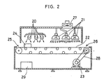
- Fig. 2 is a schematical view of the Embodiment 2 by this invention.
- the apparatus is provided with three 20W fluorescent lamps (20) and three 250W halogen lamps (21) as the light sources of the irradiation light.
- the object (24) introduced from the inlet (25) into the apparatus is irradiated by the irradiation light of relatively weak radiation intensity by the fluorescent lamps (20).
- the object As the object is moved toward the halogen lamps (21) by the action of the conveyor (22), it is irradiated by strong irradiation light of the halogen lamps (21) and is brought out of the apparatus.
- the flux density of the irradiation light in this apparatus was 50 kiloluxes below the fluorescent lamps (20), and 1,500 kiloluxes below the halogen lamps (21).
- light-curing resins were prepared by maxing 90 weight parts of methylmethacrylate, 10 weight parts of triethyleneglycol-dimethacrylate, 0.1 weight part of camphorquinone and 0.1 weight part of benzoyl peroxide. After stirring thoroughly, they were filled into a light transmission type forming mold for the molding of contact lens made of poly-4-methyl-1-pentene, and it was placed at the inlet (25) of the apparatus.
- the moving speed of the conveyor (22) was 5 cm/min., and the conveyor was 100 cm long.
- the forming mold irradiated by visible light from the fluorescent lamps (20) and halogen lamps (21) was brought out of the outlet (26).
- the forming mold with different radius of curvature was prepared and various types of contact lenses having the refraction power in the range from +12 diopters to -16 diopters were produced. In all cases, perfect mold products were obtained.
- Fig. 3 is a schematical view of the apparatus showing Embodiment 3 of this invention.
- the mechanism to move the object (37) consists of four rotary tables (36), which are rotated by 90 degrees each by the action of a motor (35) after the time set by the timer for rotary table rotation (40) has elapsed.
- 150W halogen lamps are furnished in the quantity of two (30), four (31) and six (32) above three positions of the rotary table.
- the inlet-outlet (33) is provided in order to place the objects into the apparatus or to take them out of the apparatus when the irradiation is completed.
- the flux density of the irradiation light in this apparatus was 180 kiloluxes below the halogen lamps (30), 300 kiloluxes below the halogen lamps (31) and 500 kiloluxes below the halogen lamps (32).
- power switch (38) is turned on to light up the halogen lamps (30), (31) and (32), and the objects (37) are placed on the rotary tables at the inlet-outlet (33).
- the switch (39) for rotating the rotary table is turned on to rotate the rotary table (36) by 90 degrees and to move the object to the position where two halogen lamps (30) are lighted.
- the rotary table (36) When the time set by the timer (40) for the rotation of rotary table has elapsed again, the rotary table (36) is rotated again by 90 degrees, and the object is moved to the position where four halogen lamps (31) are lighted. In this way, after the irradiation light from 6 halogen lamps (32) are irradiated on the object, the object (37) comes again to the position of the inlet-outlet (33). Then, the object is taken out of the equipment.
- the inlet and the outlet for the objects are furnished at the same position. For this reason, the operator can set and take out the objects without moving and the space requirement for the apparatus can be minimized.
- the timer (40) for the rotation of rotary table was set to 10 minutes, and the switch (39) to rotate the rotary table was turned on to operate the apparatus. After 30 minutes, the irradiated specimen came to the inlet-outlet (33) again, and this was taken out and observed. No detachment was observed between the stainless steel screw and the hardened light-curing resin, and the stainless steel screw embedded in hard transparent resin without internal distortion and crack was obtained.
- Fig. 4 is a schematical view of the apparatus showing the Embodiment 4 of this invention.
- the flux density of the irradiation light is adjusted by two types of light-reducing filters (43) and (44).
- the light transmittance of the light-reducing filter (43) closer to the inlet (50) is 2%, while that of the light-reducing filter (44) at the center of the apparatus is 50%.
- the flux density of the irradiation light in this apparatus is 0.5 milliwatt/cm2 below the light-reducing filter (43), 12.5 milliwatts/cm2 under the light-reducing filter (44), and 25 milliwatts/cm2 where there is no filter.
- the light-reducing filters (43) and (44) can be replaced by the one having adequate transmittance depending upon the hardening property of the light-curing resins. By selecting the light transmittance of the light-reducing filters (43) and (44), this apparatus can be applied for the hardening of light-curing resins with different properties.
- the hard glass molds having concave and convex surfaces of meniscus lenses for eyeglasses were placed face-to-face with each other with a gasket of ethylene-ethylacrylate copolymer inserted between them.
- a cavity to form an eyeglass lens was prepared.
- light-curing resins were prepared by mixing 50 weight parts of methylmethacrylate, 50 weight parts of KAYARAD DPCA 120 (manufactured by Nippon Kayaku; 6-functional acrylate), and 3 weight parts of 1-hydroxycyclohexyl-phenylketone. After stirring up thoroughly, the resins were injected into the cavity without mixing air bubbles, and this was placed on the inlet (50) of the apparatus.
- the conveyor (45) of this apparatus was 200 cm long, and the moving speed of the conveyor was 10 cm/min.
- the irradiated object was brought out of the outlet (51).
- the mold was disassembled and the hardened product was taken out, there was neither crack nor optical distortion, and the eyeglass lens made of hardened light-curing resins having excellent surface hardness was obtained.
- the optical surface of the eyeglass lens thus obtained was extremely smooth, and the surface accuracy was exactly the same as that of the glass mold.
- bi-focal eyeglass lens was produced by this apparatus, using a glass mold having a concaved portion with partial linear steps to produce bi-focal lens.
- the eyeglass lens made of hardened light-curing resins thus obtained, no crack was seen at the stepped portion of the lens, and the performance characteristics were as superb as the above eyeglass lens.
- Fig. 5 is a schematical view of the apparatus showing the Embodiment 5 of this invention.
- This apparatus is provided with 12 halogen lamps (61), (62) and (63) forming Zone 1 to Zone 3, each containing 4 lamps, above the conveyor (64) as the light sources.
- the radiation intensity from the halogen lamps (150W ⁇ 4) in each zone can be adjusted independently by variable transformers (67), (68) and (69) for light adjustment.
- this apparatus is provided with a variable transformer (76) for conveyor speed adjustment to adjust the rotating speed of the motor (65) and to set the moving speed of the conveyor (64).
- the light irradiation condition can be set in wide range depending upon the hardening property of the objects to be irradiated.
- light-curing resins were prepared by mixing 39 weight parts of methylmethacrylate, 52 weight parts of bisphenol-A-ethyleneglycol modified dimethacrylate, 9 weight parts of the hydrophobic silica fume (Nippon Aerosil; R-972), 0.7 weight part of camphorquinone, and 0.7 weight part of benzoyl peroxide. After stirring well, the resins were injected into the light transmission type forming mold for the molding of the bracket made of poly-4-methyl-1-pentene.
- the forming mold was placed at the inlet (71) of this apparatus, and the conveyor (64) was driven for light irradiation.
- the conveyor (64) of this apparatus was 180 cm long, and the moving speed was set to 9 cm/min.
- variable transformer (67) for light adjustment of halogen lamps in Zone 1 was set to 30V, the variable transformer (68) in Zone 2 to 78V, and the variable transformer (69) in Zone 3 to 85V.
- the flux density of the irradiation light was 4 kiloluxes in Zone 1, 140 kiloluxes in Zone 2, and 200 kiloluxes in Zone 3.
- Fig. 6 is a schematical view of the apparatus showing the Embodiment 6 of this invention.
- This apparatus is provided with 3 fluorescent lamps (80) giving relatively low flux density and 6 halogen lamps (81) and (82) above and below giving relatively high flux density. Further, it is furnished with a far infrared heater (83) at the outlet (95) of the conveyor (85) to heat the object (92) already irradiated.
- halogen lamps (81) and (82) used in this apparatus the radiation intensity of 3 lamps above and 3 lamps below are independently controlled by the variable transformers (89) and (90) for the adjustment of halogen lamp light.
- the apparatus is provided with a temperature sensor (96) and a heater temperature regulator (91) to arbitrarily control the temperature of the atmosphere heated by the far infrared heater (83). Accordingly, the flux density of the irradiation light can be set to 2 steps and the object already irradiated can be heat-treated at the desired temperature. Thus, it is possible by this apparatus to perform adequate light irradiation and the heat treatment to improve dynamic and optical properties of the object on a single conveyor.
- the apparatus is suitable for the hardening of such object which is too thick to be uniformly hardened on upper and lower surfaces by the irradiation only from one direction or which cannot be irradiated perfectly by the light irradiation from above only.
- the conveyor (85) used in this apparatus is designed in the shape of caterpillar, consisting of steel frame attached on Pyrex glass for the convenient irradiation from below by the halogen lamps (82).
- the light-curing resins having the same composition as that of the Embodiment 5 were injected into the forming mold made of poly-4-methyl-1-pentene in order to mold the orthodontic bracket, and this was placed at the inlet (94) of this apparatus.
- the conveyor of this apparatus was 150 cm long, and the moving speed of the conveyor was 5 cm/min.
- variable transformer (89) to adjust the light from upper halogen lamp at the center of the equipment was set to 78V, and the variable transformer (90) to adjust the light from lower halogen lamp was set to 35V. Further, the temperature of the heated atmosphere by the far infrared heater (83) was set to 100°C by the heater temperature regulator (91).
- the flux density of the irradiation light in this apparatus was 45 kiloluxes below the fluorescent lamp (80), 140 kiloluxes below halogen lamps (81), and 6 kiloluxes above the halogen lamps (82).
- the forming mold already irradiated and heat-treated was brought out of the outlet (95).
- a bracket made of composite resin was obtained, which has no crack inside and very few surface roughness.
- the base surface of the composite resin bracket was attached on the holder for tensile test and piano wire was bound on the wing to measure the rupture strength of the wing by Instron universal tester, the rupture strength was 5.6 ⁇ 0.5 kgf. This strength was 1.5 times as high as the rupture strength of the bracket obtained in the Embodiment 5.
- the halogen lamp of higher output power 250W
- the halogen lamp (10) of lower output power 50W
- tooth embedded sample was produced by the same procedure as in Embodiment 1.
- the embedded product thus produced showed extreme detachment between the embedded tooth and the hardened resin, and innumerable cracks were found on the surface of the embedded tooth because of abnormal temperature rise exceeding 150°C during polymerization.
- the halogen lamps (21) were removed and three 20W fluorescent lamps were installed. Then, contact lens was molded by the same procedure as in the Embodiment 2.
- the molded products thus obtained had neither crack nor optical distortion, and the radius of curvature was exactly the same as that of the forming mold. However, the surface hardness was extremely low, and innumerable flaws occurred on the surface during normal handling, resulting in the loss of transparency and showing the lack of practical applicability.
- the fluorescent lamps (20) were removed instead of removing halogen lamps (21) in the Embodiment 2 and three 250W halogen lamps were installed. Then, contact lens was molded by the same procedure as in the Embodiment 2. The molded product thus obtained showed numerous cracks. In many cases, the product had optical distortion inside the lens although it was externally satisfactory, and the product lacked the suitability for practical production.
- the light-reducing filters (43) and (44) were removed, and the eyeglass lens was hardened by the same procedure as in the Embodiment 4.
- the hardened object thus produced showed optical distortion when it was thick.
- corrugated defects were found on the surface or the surface was deformed.
- the eyeglass lens made of light-curing resins was molded by the method of the Embodiment 4 using the apparatus of this invention. In the lens with high thickness and larger refraction power, optical distortion and uneven hardening were found.
- the voltage of the variable transformers (67), (68) and (69) for the adjustment of halogen lamp light from Zone 1 to Zone 3 was set to 85V, and the composite resin bracket was hardened by the same procedure as in the Embodiment 5.
- the bracket thus produced showed cracks at the slot in many cases.
- the production yield was less than 70%, showing low productivity.
- a variable transformer (102) for the adjustment of light was provided for this batch type hardening apparatus.
- the object was hardened by the following procedure: The voltage of the variable transformer (102) for light adjustment was set to 30V, and the light was irradiated for 10 minutes on the object (103). Then, the voltage of the variable transformer (102) for light adjustment was set to 78V, and light was irradiated for 10 minutes. Finally, the voltage was set to 85V, and light was irradiated for 10 minutes.
- the molded composite resin brackets showed no defect such as internal crack or surface roughness, whereas there were variations in the rupture strength of the wing, and the quality was not stable.
- the method and the apparatus for the continuous hardening of light-curing resins according to the present invention have the following features: 1) defects such as crack, flaws, internal distortion, etc., rarely occur even when relatively thick resin objects are hardened; 2) resin molding can be done in an easy and simple manner, and continuous production is achievable; 3) the hardened resin products obtained have stable qualities; and, 4) hardened resin products with high dimensional accuracy are obtained.
- the present invention thus offers: (1) a method to continuously harden light-curing resins, characterised in that the light is irradiated on the object made of light-curing resins in continuous movement by changing the flux density of the irradiation light in multiple steps corresponding to the moving positions of the object, and (2) an apparatus to continuously harden light-curing resins, comprising equipment to continuously move the object and equipment for irradiation light adjustment, characterised in that the irradiation light adjustment equipment is provided with a means to control and irradiate the irradiation light with different flux density changing in multiple steps corresponding to the moving positions of the object.
- the flux density of the light irradiated on the object in movement is changed stepwise depending upon the position and the location of the object.
- the flux density of the light irradiated on the object is changed according to the movement of the object.
- the polymerization speed of the object and the hardening depth can be controlled in relation to the position and the time.
Landscapes
- Health & Medical Sciences (AREA)
- Oral & Maxillofacial Surgery (AREA)
- Thermal Sciences (AREA)
- Physics & Mathematics (AREA)
- Veterinary Medicine (AREA)
- Animal Behavior & Ethology (AREA)
- General Health & Medical Sciences (AREA)
- Public Health (AREA)
- Life Sciences & Earth Sciences (AREA)
- Epidemiology (AREA)
- Dentistry (AREA)
- Toxicology (AREA)
- Heating, Cooling, Or Curing Plastics Or The Like In General (AREA)
- Exposure Of Semiconductors, Excluding Electron Or Ion Beam Exposure (AREA)
- Exposure And Positioning Against Photoresist Photosensitive Materials (AREA)
- Coating Apparatus (AREA)
- Physical Or Chemical Processes And Apparatus (AREA)
Applications Claiming Priority (2)
| Application Number | Priority Date | Filing Date | Title |
|---|---|---|---|
| JP1226971A JPH0698628B2 (ja) | 1989-09-01 | 1989-09-01 | 可視光重合型レジンの連続硬化方法及び装置 |
| JP226971/89 | 1989-09-01 |
Publications (3)
| Publication Number | Publication Date |
|---|---|
| EP0415508A2 true EP0415508A2 (fr) | 1991-03-06 |
| EP0415508A3 EP0415508A3 (en) | 1991-07-24 |
| EP0415508B1 EP0415508B1 (fr) | 1996-12-11 |
Family
ID=16853489
Family Applications (1)
| Application Number | Title | Priority Date | Filing Date |
|---|---|---|---|
| EP90300083A Expired - Lifetime EP0415508B1 (fr) | 1989-09-01 | 1990-01-04 | Procédé et appareil pour le durcissement en continu de résines durcissables par la lumière |
Country Status (4)
| Country | Link |
|---|---|
| US (1) | US5135686A (fr) |
| EP (1) | EP0415508B1 (fr) |
| JP (1) | JPH0698628B2 (fr) |
| DE (1) | DE69029348T2 (fr) |
Cited By (17)
| Publication number | Priority date | Publication date | Assignee | Title |
|---|---|---|---|---|
| DE29606991U1 (de) * | 1996-04-19 | 1996-06-27 | D. Krieger GmbH, 41238 Mönchengladbach | Vorrichtung zum Erwärmen profilierter Flächen mittels Wärmestrahlung |
| EP0815146A4 (fr) * | 1995-03-20 | 1998-02-11 | ||
| WO1999022669A1 (fr) * | 1997-11-04 | 1999-05-14 | Jeneric Pentron Incorporated | Appareil servant a polymeriser des matieres dentaires en continu |
| WO1999024977A1 (fr) * | 1997-11-12 | 1999-05-20 | First Light Technology, Inc. | Systeme et procede de formation de disques colles de stockage d'informations avec un ensemble emettant une lumiere de faible puissance |
| WO1999056927A1 (fr) * | 1998-05-07 | 1999-11-11 | Lohmann Gmbh & Co. Kg | Procede et dispositif pour produire des couches auto-adhesives segmentees et les appliquer sur un substrat |
| EP0935243A3 (fr) * | 1995-08-15 | 1999-12-08 | Dainippon Ink And Chemicals, Inc. | Methode et dispositif pour coller des disques |
| FR2797173A1 (fr) * | 1999-08-06 | 2001-02-09 | Arnaud Delahaye | Procede et appareil de photopolymerisation d'une masse de reconstitution d'une prothese dentaire |
| US6352612B1 (en) | 1998-05-19 | 2002-03-05 | Steag Hamatech, Inc. | System for forming bonded storage disks with low power light assembly |
| WO2003082142A1 (fr) * | 2002-03-26 | 2003-10-09 | Dentsply International Inc. | Systeme et procede de photopolymerisation |
| EP1387765A4 (fr) * | 2001-05-04 | 2005-12-28 | Xenon Corp | Systeme a deux lampes pour la fabrication de dvd |
| EP1637312A1 (fr) * | 2004-09-16 | 2006-03-22 | Novartis AG | Procédé et dispositif pour la fabrication d'objets, surtout lentilles ophthalmiques |
| EP1847368A1 (fr) * | 2006-04-07 | 2007-10-24 | Linde Ag | Procédé et dispositif de durcissage par rayonnement |
| WO2007120495A1 (fr) * | 2006-03-31 | 2007-10-25 | Dentsply International Inc. | Système de photopolymérisation et procédé de fabrication d'appareillages dentaires |
| EP1972302A3 (fr) * | 2007-03-20 | 2008-10-01 | Wegold Edelmetalle AG | Dispositif et appareil de durcissement à la lumière de matériau dentaire, en particulier pour la polymérisation induite par la lumière |
| CN101878101A (zh) * | 2007-11-29 | 2010-11-03 | 陶氏环球技术公司 | 可微波加热的单乙烯基芳族聚合物 |
| WO2020078538A1 (fr) * | 2018-10-16 | 2020-04-23 | Transitions Optical, Ltd. | Appareil de durcissement aux ultraviolets |
| KR102575220B1 (ko) * | 2023-02-17 | 2023-09-06 | 송은영 | 치과용 하이브리드 복합 레진블록의 제작을 위한 광 중합기 |
Families Citing this family (82)
| Publication number | Priority date | Publication date | Assignee | Title |
|---|---|---|---|---|
| US5529728A (en) | 1986-01-28 | 1996-06-25 | Q2100, Inc. | Process for lens curing and coating |
| US6201037B1 (en) | 1986-01-28 | 2001-03-13 | Ophthalmic Research Group International, Inc. | Plastic lens composition and method for the production thereof |
| US6730244B1 (en) | 1986-01-28 | 2004-05-04 | Q2100, Inc. | Plastic lens and method for the production thereof |
| US5415816A (en) | 1986-01-28 | 1995-05-16 | Q2100, Inc. | Method for the production of plastic lenses |
| JPH04280824A (ja) * | 1991-03-06 | 1992-10-06 | Canon Inc | 光学素子の製造装置 |
| JPH06208812A (ja) * | 1992-03-19 | 1994-07-26 | Nitto Denko Corp | 樹脂成形体の注型方法 |
| WO1994021715A1 (fr) * | 1993-03-23 | 1994-09-29 | Tokai University | Procede et appareil pour modifier une surface solide |
| US6689426B1 (en) * | 1993-03-23 | 2004-02-10 | Tokai University | Solid surface modification method and apparatus |
| US5422046A (en) * | 1993-08-31 | 1995-06-06 | Essilor Of America, Inc. | Method for producing optical lenses |
| US5597519A (en) * | 1994-06-10 | 1997-01-28 | Johnson & Johnson Vision Products, Inc. | Ultraviolet cycling oven for polymerization of contact lenses |
| IL113904A0 (en) * | 1994-06-10 | 1995-08-31 | Johnson & Johnson Vision Prod | Mold clamping and precure of a polymerizable hydrogel |
| US5746967A (en) * | 1995-06-26 | 1998-05-05 | Fox Lite, Inc. | Method of curing thermoset resin with visible light |
| US6022498A (en) | 1996-04-19 | 2000-02-08 | Q2100, Inc. | Methods for eyeglass lens curing using ultraviolet light |
| DE19618542C2 (de) * | 1996-05-08 | 2000-12-14 | Ivoclar Ag Schaan | Polymerisationsgerät sowie Verfahren zum Steuern eines Polymerisationsgeräts |
| US6280171B1 (en) | 1996-06-14 | 2001-08-28 | Q2100, Inc. | El apparatus for eyeglass lens curing using ultraviolet light |
| US5989462A (en) * | 1997-07-31 | 1999-11-23 | Q2100, Inc. | Method and composition for producing ultraviolent blocking lenses |
| DE29812835U1 (de) * | 1998-07-18 | 1998-09-24 | UV Reline. tec GmbH & Co., 87437 Kempten | Strahlungsquelle für die Bestrahlung von Innenwänden langgestreckter Hohlräume |
| US6451226B1 (en) | 1998-09-25 | 2002-09-17 | Q2100, Inc. | Plastic lens compositions |
| US6419873B1 (en) | 1999-03-19 | 2002-07-16 | Q2100, Inc. | Plastic lens systems, compositions, and methods |
| US6960312B2 (en) * | 2000-03-30 | 2005-11-01 | Q2100, Inc. | Methods for the production of plastic lenses |
| US6716375B1 (en) | 2000-03-30 | 2004-04-06 | Q2100, Inc. | Apparatus and method for heating a polymerizable composition |
| US6723260B1 (en) | 2000-03-30 | 2004-04-20 | Q2100, Inc. | Method for marking a plastic eyeglass lens using a mold assembly holder |
| US6698708B1 (en) | 2000-03-30 | 2004-03-02 | Q2100, Inc. | Gasket and mold assembly for producing plastic lenses |
| US6632535B1 (en) | 2000-06-08 | 2003-10-14 | Q2100, Inc. | Method of forming antireflective coatings |
| US7139636B2 (en) | 2001-02-20 | 2006-11-21 | Q2100, Inc. | System for preparing eyeglass lenses with bar code reader |
| US6790022B1 (en) | 2001-02-20 | 2004-09-14 | Q2100, Inc. | Apparatus for preparing an eyeglass lens having a movable lamp mount |
| US6676399B1 (en) | 2001-02-20 | 2004-01-13 | Q2100, Inc. | Apparatus for preparing an eyeglass lens having sensors for tracking mold assemblies |
| US7025910B2 (en) | 2001-02-20 | 2006-04-11 | Q2100, Inc | Method of entering prescription information |
| US7052262B2 (en) | 2001-02-20 | 2006-05-30 | Q2100, Inc. | System for preparing eyeglasses lens with filling station |
| US6709257B2 (en) | 2001-02-20 | 2004-03-23 | Q2100, Inc. | Eyeglass lens forming apparatus with sensor |
| US7060208B2 (en) | 2001-02-20 | 2006-06-13 | Q2100, Inc. | Method of preparing an eyeglass lens with a controller |
| US7004740B2 (en) | 2001-02-20 | 2006-02-28 | Q2100, Inc. | Apparatus for preparing an eyeglass lens having a heating system |
| US7011773B2 (en) | 2001-02-20 | 2006-03-14 | Q2100, Inc. | Graphical interface to display mold assembly position in a lens forming apparatus |
| US6676398B2 (en) | 2001-02-20 | 2004-01-13 | Q2100, Inc. | Apparatus for preparing an eyeglass lens having a prescription reader |
| US6962669B2 (en) | 2001-02-20 | 2005-11-08 | Q2100, Inc. | Computerized controller for an eyeglass lens curing apparatus |
| US7045081B2 (en) | 2001-02-20 | 2006-05-16 | Q2100, Inc. | Method of monitoring components of a lens forming apparatus |
| US7083404B2 (en) | 2001-02-20 | 2006-08-01 | Q2100, Inc. | System for preparing an eyeglass lens using a mold holder |
| US7074352B2 (en) | 2001-02-20 | 2006-07-11 | Q2100, Inc. | Graphical interface for monitoring usage of components of a lens forming apparatus |
| US6840752B2 (en) | 2001-02-20 | 2005-01-11 | Q2100, Inc. | Apparatus for preparing multiple eyeglass lenses |
| US6752613B2 (en) | 2001-02-20 | 2004-06-22 | Q2100, Inc. | Apparatus for preparing an eyeglass lens having a controller for initiation of lens curing |
| US6893245B2 (en) | 2001-02-20 | 2005-05-17 | Q2100, Inc. | Apparatus for preparing an eyeglass lens having a computer system controller |
| US6726463B2 (en) | 2001-02-20 | 2004-04-27 | Q2100, Inc. | Apparatus for preparing an eyeglass lens having a dual computer system controller |
| US7124995B2 (en) | 2001-02-20 | 2006-10-24 | Q2100, Inc. | Holder for mold assemblies and molds |
| US6808381B2 (en) | 2001-02-20 | 2004-10-26 | Q2100, Inc. | Apparatus for preparing an eyeglass lens having a controller |
| US7051290B2 (en) | 2001-02-20 | 2006-05-23 | Q2100, Inc. | Graphical interface for receiving eyeglass prescription information |
| US6612828B2 (en) | 2001-02-20 | 2003-09-02 | Q2100, Inc. | Fill system with controller for monitoring use |
| US6758663B2 (en) | 2001-02-20 | 2004-07-06 | Q2100, Inc. | System for preparing eyeglass lenses with a high volume curing unit |
| US6875005B2 (en) | 2001-02-20 | 2005-04-05 | Q1200, Inc. | Apparatus for preparing an eyeglass lens having a gating device |
| US6899831B1 (en) | 2001-02-20 | 2005-05-31 | Q2100, Inc. | Method of preparing an eyeglass lens by delayed entry of mold assemblies into a curing apparatus |
| US7037449B2 (en) | 2001-02-20 | 2006-05-02 | Q2100, Inc. | Method for automatically shutting down a lens forming apparatus |
| US6702564B2 (en) | 2001-02-20 | 2004-03-09 | Q2100, Inc. | System for preparing an eyeglass lens using colored mold holders |
| US6863518B2 (en) | 2001-02-20 | 2005-03-08 | Q2100, Inc. | Mold filing apparatus having multiple fill stations |
| US6790024B2 (en) | 2001-02-20 | 2004-09-14 | Q2100, Inc. | Apparatus for preparing an eyeglass lens having multiple conveyor systems |
| US6712331B2 (en) | 2001-02-20 | 2004-03-30 | Q2100, Inc. | Holder for mold assemblies with indicia |
| US6655946B2 (en) | 2001-02-20 | 2003-12-02 | Q2100, Inc. | Apparatus for preparing an eyeglass lens having a controller for conveyor and curing units |
| DE10115066B4 (de) * | 2001-03-27 | 2012-10-04 | Leica Biosystems Nussloch Gmbh | Vorrichtung zum Trocknen lösungsmittelbasierender Tinte |
| EP1429325A4 (fr) * | 2001-09-13 | 2006-05-31 | Tdk Corp | Procede de production de support d'enregistrement optique |
| US6655040B2 (en) * | 2002-01-04 | 2003-12-02 | The Diagnostics Group, Inc. | Combination ultraviolet curing and infrared drying system |
| US7044429B1 (en) | 2002-03-15 | 2006-05-16 | Q2100, Inc. | Methods and systems for coating eyeglass lens molds |
| US6464484B1 (en) | 2002-03-30 | 2002-10-15 | Q2100, Inc. | Apparatus and system for the production of plastic lenses |
| JP3898579B2 (ja) * | 2002-06-21 | 2007-03-28 | 東京エレクトロン株式会社 | 基板処理装置 |
| US20060065989A1 (en) * | 2004-09-29 | 2006-03-30 | Thad Druffel | Lens forming systems and methods |
| DE102005003802A1 (de) * | 2004-12-10 | 2006-06-14 | Nütro Maschinen- und Anlagenbau GmbH & Co. KG | Strahlungsgerät sowie Pulverauftragsstation und Anordnung zur Beschichtung von temperatursensiblen Materialien und Verfahren hierzu |
| JP4679944B2 (ja) * | 2005-03-24 | 2011-05-11 | 富士フイルム株式会社 | 複合レンズの製造方法及びその装置 |
| US7638780B2 (en) * | 2005-06-28 | 2009-12-29 | Eastman Kodak Company | UV cure equipment with combined light path |
| US7785092B2 (en) * | 2005-08-09 | 2010-08-31 | Coopervision International Holding Company, Lp | Systems and methods for producing contact lenses from a polymerizable composition |
| US7731873B2 (en) * | 2005-08-09 | 2010-06-08 | Coopervision International Holding Company, Lp | Contact lens mold assemblies and systems and methods of producing same |
| US20090202714A1 (en) * | 2005-11-21 | 2009-08-13 | Mandzy Natalia S | Methods of Making and using Metal Oxide Nanoparticles |
| JP4738319B2 (ja) * | 2006-11-15 | 2011-08-03 | 大日本スクリーン製造株式会社 | パターン形成装置 |
| US8465337B2 (en) * | 2007-06-18 | 2013-06-18 | Anthony R. Eisenhut | Radiation curable arts and crafts toy |
| EP2349072B1 (fr) * | 2008-08-06 | 2013-07-03 | Naym 55 Dental Technologies Ltd. | Appareil et procédé de conditionnement de prothèse dentaire |
| EP2407122B1 (fr) * | 2010-07-16 | 2016-07-06 | Ivoclar Vivadent AG | Four à micro-ondes doté d'un plateau rotatif |
| US9108338B2 (en) | 2011-04-13 | 2015-08-18 | Align Technology, Inc. | Methods and systems for thermal forming an object |
| JP5121996B1 (ja) * | 2011-11-15 | 2013-01-16 | 株式会社 ニュー・サンワ | ウレタン加硫コントロールコンベヤー装置 |
| JP5658133B2 (ja) * | 2011-12-27 | 2015-01-21 | 株式会社モリタ製作所 | 医療用x線撮影装置用ファントム |
| EP3068601A1 (fr) * | 2013-11-12 | 2016-09-21 | Bombardier Inc. | Système et procédé de durcissement par rayonnement de matériaux composites |
| CN104647661B (zh) * | 2013-11-22 | 2017-05-10 | 青岛海尔模具有限公司 | 一种热烘除应力设备 |
| MX2016012308A (es) | 2014-03-24 | 2016-11-30 | Dws Srl | Horno de fotocurado. |
| JP6423960B2 (ja) * | 2014-11-04 | 2018-11-14 | ディーダブリューエス エス.アール.エル. | ステレオリソグラフィ方法および組成物 |
| CN104880862B (zh) * | 2015-06-26 | 2018-03-16 | 京东方科技集团股份有限公司 | 一种彩膜基板的制备方法、显示面板、显示装置 |
| EP4166523B1 (fr) * | 2021-10-14 | 2023-11-29 | Ivoclar Vivadent AG | Dispositif d'éclairage permettant d'éclairer un objet dentaire |
| EP4166524B1 (fr) | 2021-10-14 | 2023-11-22 | Ivoclar Vivadent AG | Four permettant de chauffer un objet dentaire |
Family Cites Families (16)
| Publication number | Priority date | Publication date | Assignee | Title |
|---|---|---|---|---|
| FR1080987A (fr) * | 1952-11-07 | 1954-12-15 | Continental Gummi Werke Ag | Procédé pour la fabrication de tuyaux flexibles |
| US4073835A (en) * | 1976-01-30 | 1978-02-14 | Toyo Ink Manufacturing Co., Ltd. | Method of resin encapsulating electrical parts with UV curing of fire retardant resin |
| FR2348227A1 (fr) * | 1976-04-14 | 1977-11-10 | Rhone Poulenc Ind | Perfectionnement aux procedes de preparation de polymeres acryliques hydrosolubles par photopolymerisation |
| US4132518A (en) * | 1977-10-18 | 1979-01-02 | Realite Optical Company | Apparatus for manufacturing plastic lenses |
| JPS55102A (en) * | 1978-03-15 | 1980-01-05 | Sankin Ind Co | Preparation of false tooth floor by photoohardening and photoohardening material |
| US4329135A (en) * | 1980-03-19 | 1982-05-11 | Technics Lambda International | Device for the continuous thermal or thermo-chemical treatment of objects by emission of micro-waves |
| DE3029276A1 (de) * | 1980-08-01 | 1982-02-18 | Etablissement Dentaire Ivoclar, Schaan | Photopolymerisierbare masse, insbesondere fuer dentalzwecke |
| FR2507296A1 (fr) * | 1981-06-09 | 1982-12-10 | Cladi Marcel | Enceinte pour la polymerisation a froid de produits, en particulier de produits de restauration esthetique et fonctionnelle des dents |
| JPS5898303A (ja) * | 1981-12-07 | 1983-06-11 | Sekisui Fine Chem Kk | 光硬化性樹脂組成物の硬化法 |
| US4624810A (en) * | 1982-09-27 | 1986-11-25 | Carter-Wallace, Inc. | Production of a solid stick in a container |
| IT1177945B (it) * | 1984-07-31 | 1987-08-26 | Siv Soc Italiana Vetro | Procedimento per la produzione di un nastro continuo composito comprendente una pellicola a base acrilica,adatta per l'uso in lastre di vetro laminato di sicurezza e procedotto cosi' ottenuto |
| DE3428688A1 (de) * | 1984-08-03 | 1986-02-13 | Karl-Heinz 2308 Preetz Pauli | Vakuum - box zum aushaerten von lichthaertenden kunststoffen |
| JPS6238149A (ja) * | 1985-08-13 | 1987-02-19 | 株式会社 中西歯科器械製作所 | 歯科材料の表面を硬化させるための可視光線照射装置 |
| DE3707398A1 (de) * | 1987-03-07 | 1988-09-15 | Kulzer & Co Gmbh | Bestrahlungsgeraet zum photopolymerisieren von kunststoff-einbettmassen fuer histologische praeparate |
| US4913859A (en) * | 1987-10-30 | 1990-04-03 | At&T Bell Laboratories | Methods of curing optical fiber coatings |
| US4879073A (en) * | 1988-04-22 | 1989-11-07 | United Technologies Corporation | Process of high pressure curing with ultraviolet radiation |
-
1989
- 1989-09-01 JP JP1226971A patent/JPH0698628B2/ja not_active Expired - Lifetime
- 1989-12-29 US US07/459,161 patent/US5135686A/en not_active Expired - Lifetime
-
1990
- 1990-01-04 DE DE69029348T patent/DE69029348T2/de not_active Expired - Lifetime
- 1990-01-04 EP EP90300083A patent/EP0415508B1/fr not_active Expired - Lifetime
Cited By (23)
| Publication number | Priority date | Publication date | Assignee | Title |
|---|---|---|---|---|
| EP0815146A4 (fr) * | 1995-03-20 | 1998-02-11 | ||
| US6334925B1 (en) | 1995-08-15 | 2002-01-01 | Dainippon Ink & Chemical, Inc. | Disc bonding method |
| EP0935243A3 (fr) * | 1995-08-15 | 1999-12-08 | Dainippon Ink And Chemicals, Inc. | Methode et dispositif pour coller des disques |
| DE29606991U1 (de) * | 1996-04-19 | 1996-06-27 | D. Krieger GmbH, 41238 Mönchengladbach | Vorrichtung zum Erwärmen profilierter Flächen mittels Wärmestrahlung |
| WO1999022669A1 (fr) * | 1997-11-04 | 1999-05-14 | Jeneric Pentron Incorporated | Appareil servant a polymeriser des matieres dentaires en continu |
| WO1999024977A1 (fr) * | 1997-11-12 | 1999-05-20 | First Light Technology, Inc. | Systeme et procede de formation de disques colles de stockage d'informations avec un ensemble emettant une lumiere de faible puissance |
| WO1999056927A1 (fr) * | 1998-05-07 | 1999-11-11 | Lohmann Gmbh & Co. Kg | Procede et dispositif pour produire des couches auto-adhesives segmentees et les appliquer sur un substrat |
| US6527897B1 (en) | 1998-05-07 | 2003-03-04 | Lohmann Gmbh & Co. Kg | Method and device for producing segmented contact adhesive layers and for applying the same on a substrate |
| US6500297B1 (en) | 1998-05-19 | 2002-12-31 | Steag Hamatech, Inc. | Method of forming bonded storage disks with low power light assembly |
| US6352612B1 (en) | 1998-05-19 | 2002-03-05 | Steag Hamatech, Inc. | System for forming bonded storage disks with low power light assembly |
| WO2001010336A1 (fr) * | 1999-08-06 | 2001-02-15 | Arnaud Delahaye | Procede et appareil de photopolymerisation d'une masse de reconstitution d'une prothese dentaire |
| FR2797173A1 (fr) * | 1999-08-06 | 2001-02-09 | Arnaud Delahaye | Procede et appareil de photopolymerisation d'une masse de reconstitution d'une prothese dentaire |
| EP1387765A4 (fr) * | 2001-05-04 | 2005-12-28 | Xenon Corp | Systeme a deux lampes pour la fabrication de dvd |
| WO2003082142A1 (fr) * | 2002-03-26 | 2003-10-09 | Dentsply International Inc. | Systeme et procede de photopolymerisation |
| WO2006029865A1 (fr) * | 2004-09-16 | 2006-03-23 | Novartis Ag | Procede et dispositif de fabrication de moulages, notamment de lentilles ophtalmiques |
| EP1637312A1 (fr) * | 2004-09-16 | 2006-03-22 | Novartis AG | Procédé et dispositif pour la fabrication d'objets, surtout lentilles ophthalmiques |
| WO2007120495A1 (fr) * | 2006-03-31 | 2007-10-25 | Dentsply International Inc. | Système de photopolymérisation et procédé de fabrication d'appareillages dentaires |
| EP1847368A1 (fr) * | 2006-04-07 | 2007-10-24 | Linde Ag | Procédé et dispositif de durcissage par rayonnement |
| EP1972302A3 (fr) * | 2007-03-20 | 2008-10-01 | Wegold Edelmetalle AG | Dispositif et appareil de durcissement à la lumière de matériau dentaire, en particulier pour la polymérisation induite par la lumière |
| CN101878101A (zh) * | 2007-11-29 | 2010-11-03 | 陶氏环球技术公司 | 可微波加热的单乙烯基芳族聚合物 |
| WO2020078538A1 (fr) * | 2018-10-16 | 2020-04-23 | Transitions Optical, Ltd. | Appareil de durcissement aux ultraviolets |
| US12064930B2 (en) | 2018-10-16 | 2024-08-20 | Transitions Optical, Ltd. | Ultraviolet curing apparatus |
| KR102575220B1 (ko) * | 2023-02-17 | 2023-09-06 | 송은영 | 치과용 하이브리드 복합 레진블록의 제작을 위한 광 중합기 |
Also Published As
| Publication number | Publication date |
|---|---|
| US5135686A (en) | 1992-08-04 |
| EP0415508B1 (fr) | 1996-12-11 |
| JPH0390320A (ja) | 1991-04-16 |
| DE69029348D1 (de) | 1997-01-23 |
| EP0415508A3 (en) | 1991-07-24 |
| JPH0698628B2 (ja) | 1994-12-07 |
| DE69029348T2 (de) | 1997-04-10 |
Similar Documents
| Publication | Publication Date | Title |
|---|---|---|
| EP0415508B1 (fr) | Procédé et appareil pour le durcissement en continu de résines durcissables par la lumière | |
| US5135685A (en) | Method and apparatus for continuous hardening of visible light-curing resins | |
| Takamata et al. | Adaptation of acrylic resin dentures as influenced by the activation mode of polymerization | |
| US4919850A (en) | Method for curing plastic lenses | |
| US4645649A (en) | Apparatus for curing resin films coated on dental resin prosthesis | |
| DE69411468T2 (de) | Verfahren zur Herstellung optischer Linsen | |
| US5104591A (en) | Method for light curing of dental light-curing resins | |
| US5912470A (en) | Process and an apparatus for the curing of light-sensitive polymeric compositions | |
| US5028358A (en) | Method for molding and curing plastic lenses | |
| JPH0541411B2 (fr) | ||
| DE69222349T2 (de) | Vorrichtung und Verfahren zum Härten einer Gebissprothese | |
| EP1629961B1 (fr) | Prédurcissement au moyen d'un masque des lentilles de contact: systèmes et procédé | |
| JPH01198312A (ja) | プラスチックレンズ成形方法およびその装置 | |
| JP6840149B2 (ja) | 重合した大きな歯科材料ブロックを製造する方法 | |
| US6843951B2 (en) | Method and apparatus for making a dental device or the like | |
| EP1212188B1 (fr) | Dispositif d'illumination uv | |
| JP2800898B2 (ja) | 非球面光学素子の製造方法 | |
| JPH0355212A (ja) | 可視光重合型レジンの硬化装置 | |
| RU2171653C1 (ru) | Способ изготовления пломбировочных вкладок | |
| Gladrow et al. | The effect of nitrogen atmosphere during post-curing on cytotoxicity, polishability, flexural strength, and surface hardness of 3D-printed denture bases: an in vitro study | |
| JPS61217152A (ja) | 歯科用レジン重合法及びその装置 | |
| JPH02280744A (ja) | 歯科装着用物品の作製方法およびその製造装置 | |
| Majeed | Effect of Addition Retention Bead and Repair Material on Transverse Strength of Repaired Acrylic Denture Resin | |
| JPH06289204A (ja) | プラスチック製模様入り板の製造方法 | |
| JPS61215016A (ja) | レジン重合法及びその装置 |
Legal Events
| Date | Code | Title | Description |
|---|---|---|---|
| PUAI | Public reference made under article 153(3) epc to a published international application that has entered the european phase |
Free format text: ORIGINAL CODE: 0009012 |
|
| AK | Designated contracting states |
Kind code of ref document: A2 Designated state(s): BE DE FR GB |
|
| PUAL | Search report despatched |
Free format text: ORIGINAL CODE: 0009013 |
|
| AK | Designated contracting states |
Kind code of ref document: A3 Designated state(s): BE DE FR GB |
|
| 17P | Request for examination filed |
Effective date: 19920109 |
|
| 17Q | First examination report despatched |
Effective date: 19931005 |
|
| GRAG | Despatch of communication of intention to grant |
Free format text: ORIGINAL CODE: EPIDOS AGRA |
|
| GRAH | Despatch of communication of intention to grant a patent |
Free format text: ORIGINAL CODE: EPIDOS IGRA |
|
| GRAH | Despatch of communication of intention to grant a patent |
Free format text: ORIGINAL CODE: EPIDOS IGRA |
|
| GRAA | (expected) grant |
Free format text: ORIGINAL CODE: 0009210 |
|
| AK | Designated contracting states |
Kind code of ref document: B1 Designated state(s): BE DE FR GB |
|
| ET | Fr: translation filed | ||
| REF | Corresponds to: |
Ref document number: 69029348 Country of ref document: DE Date of ref document: 19970123 |
|
| PLBE | No opposition filed within time limit |
Free format text: ORIGINAL CODE: 0009261 |
|
| 26N | No opposition filed | ||
| REG | Reference to a national code |
Ref country code: GB Ref legal event code: IF02 |
|
| REG | Reference to a national code |
Ref country code: GB Ref legal event code: 732E |
|
| REG | Reference to a national code |
Ref country code: FR Ref legal event code: TQ |
|
| PGFP | Annual fee paid to national office [announced via postgrant information from national office to epo] |
Ref country code: DE Payment date: 20090123 Year of fee payment: 20 |
|
| PGFP | Annual fee paid to national office [announced via postgrant information from national office to epo] |
Ref country code: GB Payment date: 20090107 Year of fee payment: 20 |
|
| PGFP | Annual fee paid to national office [announced via postgrant information from national office to epo] |
Ref country code: BE Payment date: 20090107 Year of fee payment: 20 |
|
| REG | Reference to a national code |
Ref country code: GB Ref legal event code: PE20 Expiry date: 20100103 |
|
| BE20 | Be: patent expired |
Owner name: *JAPAN INSTITUTE OF ADVANCED DENTISTRY Effective date: 20100104 |
|
| PG25 | Lapsed in a contracting state [announced via postgrant information from national office to epo] |
Ref country code: GB Free format text: LAPSE BECAUSE OF EXPIRATION OF PROTECTION Effective date: 20100103 |
|
| PG25 | Lapsed in a contracting state [announced via postgrant information from national office to epo] |
Ref country code: DE Free format text: LAPSE BECAUSE OF EXPIRATION OF PROTECTION Effective date: 20100104 |
|
| PGFP | Annual fee paid to national office [announced via postgrant information from national office to epo] |
Ref country code: FR Payment date: 20090108 Year of fee payment: 20 |