EP0422311A1 - Dispositif pour réduire la charge sur les paliers de compresseurs à volute - Google Patents
Dispositif pour réduire la charge sur les paliers de compresseurs à volute Download PDFInfo
- Publication number
- EP0422311A1 EP0422311A1 EP89630192A EP89630192A EP0422311A1 EP 0422311 A1 EP0422311 A1 EP 0422311A1 EP 89630192 A EP89630192 A EP 89630192A EP 89630192 A EP89630192 A EP 89630192A EP 0422311 A1 EP0422311 A1 EP 0422311A1
- Authority
- EP
- European Patent Office
- Prior art keywords
- drive shaft
- counterweights
- axis
- rotation
- scroll
- Prior art date
- Legal status (The legal status is an assumption and is not a legal conclusion. Google has not performed a legal analysis and makes no representation as to the accuracy of the status listed.)
- Granted
Links
- 230000033001 locomotion Effects 0.000 claims abstract description 15
- 238000007906 compression Methods 0.000 claims description 18
- 230000006835 compression Effects 0.000 claims description 16
- 238000000034 method Methods 0.000 claims description 10
- 230000002301 combined effect Effects 0.000 claims description 4
- 238000007599 discharging Methods 0.000 claims description 2
- 208000036366 Sensation of pressure Diseases 0.000 claims 2
- 230000000694 effects Effects 0.000 claims 2
- 230000005540 biological transmission Effects 0.000 claims 1
- 229910052729 chemical element Inorganic materials 0.000 claims 1
- 238000011068 loading method Methods 0.000 abstract description 4
- 238000009826 distribution Methods 0.000 abstract description 2
- 238000010276 construction Methods 0.000 description 8
- 239000013598 vector Substances 0.000 description 7
- 238000004513 sizing Methods 0.000 description 4
- 230000001133 acceleration Effects 0.000 description 3
- 238000006243 chemical reaction Methods 0.000 description 2
- 238000004378 air conditioning Methods 0.000 description 1
- 238000001816 cooling Methods 0.000 description 1
- 230000008878 coupling Effects 0.000 description 1
- 238000010168 coupling process Methods 0.000 description 1
- 238000005859 coupling reaction Methods 0.000 description 1
- 230000001419 dependent effect Effects 0.000 description 1
- 238000004519 manufacturing process Methods 0.000 description 1
Images




Classifications
-
- F—MECHANICAL ENGINEERING; LIGHTING; HEATING; WEAPONS; BLASTING
- F16—ENGINEERING ELEMENTS AND UNITS; GENERAL MEASURES FOR PRODUCING AND MAINTAINING EFFECTIVE FUNCTIONING OF MACHINES OR INSTALLATIONS; THERMAL INSULATION IN GENERAL
- F16F—SPRINGS; SHOCK-ABSORBERS; MEANS FOR DAMPING VIBRATION
- F16F15/00—Suppression of vibrations in systems; Means or arrangements for avoiding or reducing out-of-balance forces, e.g. due to motion
- F16F15/28—Counterweights, i.e. additional weights counterbalancing inertia forces induced by the reciprocating movement of masses in the system, e.g. of pistons attached to an engine crankshaft; Attaching or mounting same
-
- F—MECHANICAL ENGINEERING; LIGHTING; HEATING; WEAPONS; BLASTING
- F04—POSITIVE - DISPLACEMENT MACHINES FOR LIQUIDS; PUMPS FOR LIQUIDS OR ELASTIC FLUIDS
- F04C—ROTARY-PISTON, OR OSCILLATING-PISTON, POSITIVE-DISPLACEMENT MACHINES FOR LIQUIDS; ROTARY-PISTON, OR OSCILLATING-PISTON, POSITIVE-DISPLACEMENT PUMPS
- F04C29/00—Component parts, details or accessories of pumps or pumping installations, not provided for in groups F04C18/00 - F04C28/00
- F04C29/0021—Systems for the equilibration of forces acting on the pump
Definitions
- the present invention relates to compressors in general, and more particularly to scroll compressors.
- Major components of a typical scroll-type vapor compressor include a support usually constructed as a housing for some or all of the other major components, fixed and orbiting scroll elements, a drive shaft provided with an eccentric crank portion and mounted on the support for rotation by respective support bearings, and a drive motor which rotates the drive shaft about its axis so that the crank portion causes the orbiting scroll element to conduct orbiting motion relative to the fixed scroll element, with the orbiting element being prevented by an appropriate coupling arrangement of any known construction from rotating with the drive shaft while still being capable of conducting the desired orbiting movement.
- Vapor compression is achieved in at least one compression space bounded by the fixed and orbiting scroll elements as the orbiting scroll element is driven by the eccentric crank shaft portion, and the pressure of the medium being compressed acts on both the fixed scroll element and the orbiting scroll element.
- Still another object of the present invention is to develop the scroll compressor of the type here under consideration in such a manner as to reduce the loading of the support bearings of its rotating drive shaft under operating conditions.
- a concomitant object of the present invention is to devise a method of balancing the compressor of the above type by choosing the sizes and positions of counterweights mounted on the crankshaft in such a manner as to minimize the support bearing loading.
- a scroll compressor which comprises a support, a fixed scroll element stationarily mounted on the support, and an orbiting scroll element mounted for orbiting motion relative to the fixed scroll element and bounding therewith at least one compression space.
- the scroll compressor of the present invention further includes means for admitting a medium to be compressed into and for discharging the medium from the compression space, a drive shaft having a main portion centered on an axis and an eccentric crank portion transversely offset from the axis, bearing means for supporting the main portion of the shaft on the support for rotation about the axis such that the crank portion acts on the orbiting scroll element, and means for rotating the drive shaft about the axis to cause the orbiting scroll element to conduct the orbiting motion with the medium being compressed in the compression space prior to its discharge, with attendant exertion of a resultant pressure force by the medium on the orbiting scroll element.
- balancing means mounted on the drive shaft for rotation therewith about the axis and having such respective masses and angular distributions about the axis as to substantially compensate for the combined effect of other eccentric masses and of the resultant pressure force on the bearing means at least when the drive shaft rotates at a predetermined speed.
- a method of balancing a scroll compressor in which a fixed scroll element is stationarily mounted on a support and an orbiting scroll element is caused by an eccentric crank portion of a drive shaft supported by respective bearings on the support for rotation about an axis to conduct orbiting motion relative to the fixed scroll element with which it bounds at least one compression space so that a medium being compressed in the compression space exerts a resultant pressure force on the orbiting scroll element.
- the method of the present invention comprises the steps of determining the magnitudes and directions of the resultant pressure force and of all inertial forces of eccentric masses at least at one speed of rotation of the drive shaft, calculating the masses and positions of at least two counterweights to be mounted on the drive shaft for joint rotation therewith about the axis such as to substantially compensate for the combined effect of the resultant pressure and inertial forces on the bearings at least during the rotation of the drive shaft at the one speed; and mounting the counterweights having the so calculated masses in the so calculated positions on the drive shaft for joint rotation therewith.
- the present invention is based on the recognition of the fact that the above-mentioned approach to counterbalancing, which is appropriate for reciprocating compressors, is less then adequate for use in scroll compressors. This is so because a detailed analysis of the pressure forces occurring in a scroll compressor indicates that the pressure component of the resultant force vector that acts on the crank portion of the drive shaft is relatively constant in magnitude and direction relative to the crank portion (the vector direction rotates with crank angle at a nearly constant relative angle to crank). The pressure force component therefore acts in a similar manner as the inertial forces and, accordingly, can and should be considered, in accordance with the present invention, when sizing and locating counterweights during dynamic balancing of the compressor.
- FIG. 10 the reference numeral 10 has been used therein to identify a typical construction of a scroll compressor suited for employing the present invention.
- the scroll compressor 10 has been illustrated in a manner that is substantially simplified without, however, omitting any features needed for understanding the invention.
- a support or housing 11 and a fixed scroll 12 constitute the main stationary components of the scroll compressor 10.
- the main kinematic components of the scroll compressor 10 include an orbiting scroll element 13, and a crankshaft 14 having a main portion 15 centered on an axis and an eccentric crank portion 17 which is transversely offset with respect to the main portion 15, being centered on an eccentric axis 18, and which acts on the orbiting scroll element 13 by being supported thereon by a scroll bearing 19.
- Such main kinematic components further include an upper counterweight 20 and a lower counterweight 21, as considered in the illustrated position which may be the operating position of the scroll compressor 10.
- the drive shaft 14 is supported on the support 11 for rotation about the axis 16 by an upper shaft or support bearing 22 and a lower shaft or support bearing 23, and is driven in rotation, in the illustrated exemplary construction of the scroll compressor 10, by a motor rotor 24 that interacts with a motor stator 25 which is shown to be accommodated in, and is stationarily mounted on, the support or housing 11.
- the orbiting motion of the orbiting scroll 13 causes various forces to be generated. Vectors of these forces are indicated in a top plan view of Figure 2a and also correspondingly in a side elevational view of Figure 2b. Radial, tangential and axial pressure forces, F pr , F pt and F pa , arise due to vapor pressure on the orbiting scroll 13.
- the radial and tangential pressure load F pr and F pt can be calculated for any angle ⁇ in accordance with the following equations: wherein the above symbols have the following meanings: F pr Radial pressure force due to orbiting scroll F pt Tangential pressure force due to orbiting scroll h Height of scroll wrap a Base circles radius of scroll involute P1,...,P N Pressure in scroll compression pockets psc Pressure in suction chamber surrounding orbiting scroll N Number of pairs of compression pockets at start of closed compression ⁇ Crank angle i Index for pair of scroll compression pockets
- Fig. 4 the resultant force F sbc that is generated by the orbiting scroll motion is shown in a diagrammatic fashion as acting on the crank 17 of the drive shaft 14 carrying the kinematic components described above in conjunction with Figure 1 and supported on the support bearings 22 and 23.
- the schematic representation of Fig. 4 uses small center-of-mass circles to indicate the relative spatial positions of the crank portion 17, the upper counterweight 20, the lower counterweight 21, and the motor rotor 24. Centers of the shaft bearings 22 and 23 are also indicated by small circles.
- Force and moment balance can be made on the crankshaft 14 using Fig. 4, to arrive at the required inertia force and location of the counterweights 20 and 21 which produce zero reaction force at the shaft bearings 22 and 23. For this reason, no forces are shown in Fig. 4 at the shaft bearings 22 and 23. Any inertia force due to motor rotor eccentricity is neglected since it should be quite small.
- FIG. 5 An example of the results obtained when using the method of this invention is shown in Fig. 5 where the locations and inertia forces of the counterweights 20 and 21 are plotted versus the crank angle.
- Fig. 5 clearly shows that the magnitude of the inertia forces is relatively constant, especially for the lower counterweight 21, and that the angular location relative to the crank is nearly constant.
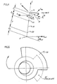
- the counterweights 20 and 21 of the present invention will be substituted for the conventional counterweights, that is, they will be situated at the same axial regions of the drive shaft 14 as the conventional counterweights and only their sizes and angular positions will be different from those of the conventional counterweights, as shown in Figure 6 of the drawing for the upper counterweight 20.
- this invention relates to an improved approach to counterbalancing radial and tangential loads generated in the scroll-type vapor compressor 10.
- the technique involves sizing and positioning counterbalance weights 20 and 21 on the drive shaft 14 such that the resultant load imparted by both the compression process and by the inertia of the moving scroll element 13 is nearly cancelled at the drive shaft support bearings 22 and 23.
- the result is a counterweight 20 that is larger than the conventional counterweight (indicated at 20′) and is located at a crank angle less than 180 degrees.
- Bearing loads calculated using the conventional balancing method, on the one hand, and the new balancing method proposed by the present invention, are shown in Figure 7 for a compressor speed of 3600 RPM.
- the method of this invention results in much lower bearing loads than the prior art approach.
- Lower bearing loads in turn translate directly to increased reliability and life in existing scroll compressors. Consequently, expensive bearings used in existing scroll compressors (such as roller bearings) could be replaced with lower cost bearings (such as journal bearings) while maintaining or improving reliability and life of the compressor.
- the counterweight used in accordance with this invention will be no more complex than those currently used, (i.e., fixed weight and position); however, the size and position of the counterweights will be different, as shown in Figure 6.
- a mechanism may be included to effectively vary the force and location of the respective counterweight 20 and/or 21 as the speed is changed to achieve the characteristics shown in Figures 8a and 8b.
- Such a mechanism could be a relatively simple passive device such as shown conceptually in Fig. 9, wherein the counterweight 20 is shown to be provided with a recess 30 which accommodates in a sliding manner an adjustment counterweight member 31 that is acted upon by a tension spring 32. It will be appreciated that, as the speed of rotation of the shaft 14 increases, the counterweight member 31 will be displaced by the centrifugal force acting thereon against the force of the tension spring 33 more and more out of the recess 30, so that the inertia force exerted thereby increases correspondingly.
- FIG. 10 Another way of implementing the above mechanism is shown if Figure 10.
- a counterweight element 33 is mounted on the counterweight 20 for pivoting about a pivot axis 34 as is acted upon by a torsion spring in the clockwise sense as considered in the drawing.
- the centrifugal force acting on the counterweight member 33 will displace the latter outwardly as the speed of rotation increases, but this time by pivoting the counterweight member 33 about the pivot 34 against the biasing action of the spring 35 in the counterclockwise direction, with attendant increase in the inertia force exerted by the counterweight member 33 via the spring 35 and the pivot 34 on the counterweight 20 and thus ultimately on the shaft 14.
- the mass, the circumferential location, and the trajectory of movement of the speed-sensitive counterweight member 30 or 33, the spring constants, etc. are highly dependent on the compressor design parameters such as the weight of the orbiting scroll element 13, the axial placement of the counterweights 20 and 21, and the operating speed range. Nevertheless, once the other parameters of the variable-speed scroll compressor 10 are known, the counterweight member parameters can easily be calculated. The additional complexity of this variable geometry counterweight 30 or 33 can easily be justified in terms of lower bearing loads over a wide speed range.
Landscapes
- Engineering & Computer Science (AREA)
- General Engineering & Computer Science (AREA)
- Mechanical Engineering (AREA)
- Physics & Mathematics (AREA)
- Acoustics & Sound (AREA)
- Aviation & Aerospace Engineering (AREA)
- Rotary Pumps (AREA)
- Structures Of Non-Positive Displacement Pumps (AREA)
- Applications Or Details Of Rotary Compressors (AREA)
Priority Applications (1)
| Application Number | Priority Date | Filing Date | Title |
|---|---|---|---|
| DE1989609600 DE68909600T2 (de) | 1989-10-12 | 1989-10-12 | Einrichtung zur Lagerleistungsreduzierung einer Verdrängermaschine nach dem Spiralprinzip. |
Applications Claiming Priority (1)
| Application Number | Priority Date | Filing Date | Title |
|---|---|---|---|
| US07/220,719 US4898520A (en) | 1988-07-18 | 1988-07-18 | Method of and arrangement for reducing bearing loads in scroll compressors |
Publications (2)
| Publication Number | Publication Date |
|---|---|
| EP0422311A1 true EP0422311A1 (fr) | 1991-04-17 |
| EP0422311B1 EP0422311B1 (fr) | 1993-09-29 |
Family
ID=22824666
Family Applications (1)
| Application Number | Title | Priority Date | Filing Date |
|---|---|---|---|
| EP89630192A Expired - Lifetime EP0422311B1 (fr) | 1988-07-18 | 1989-10-12 | Dispositif pour réduire la charge sur les paliers de compresseurs à volute |
Country Status (3)
| Country | Link |
|---|---|
| US (1) | US4898520A (fr) |
| EP (1) | EP0422311B1 (fr) |
| ES (1) | ES2044203T3 (fr) |
Cited By (2)
| Publication number | Priority date | Publication date | Assignee | Title |
|---|---|---|---|---|
| EP0656477A1 (fr) * | 1993-12-02 | 1995-06-07 | Kabushiki Kaisha Toyoda Jidoshokki Seisakusho | Compresseur du type à spirales |
| WO2008115016A1 (fr) | 2007-03-21 | 2008-09-25 | Lg Electronics Inc. | Compresseur et dispositif servant à réduire la vibration de celui-ci |
Families Citing this family (35)
| Publication number | Priority date | Publication date | Assignee | Title |
|---|---|---|---|---|
| KR950007515B1 (ko) * | 1990-01-08 | 1995-07-11 | 가부시기가이샤 히다찌 세아사꾸쇼 | 스크롤 압축기 |
| JP2738260B2 (ja) * | 1993-05-07 | 1998-04-08 | 三菱電機株式会社 | スクロール圧縮機 |
| US5290161A (en) * | 1993-06-02 | 1994-03-01 | General Motors Corporation | Control system for a clutchless scroll type fluid material handling machine |
| US5282728A (en) * | 1993-06-02 | 1994-02-01 | General Motors Corporation | Inertial balance system for a de-orbiting scroll in a scroll type fluid handling machine |
| JPH07324689A (ja) * | 1994-05-31 | 1995-12-12 | Mitsubishi Heavy Ind Ltd | スクロール型流体機械 |
| JPH1018985A (ja) * | 1996-07-05 | 1998-01-20 | Toshiba Corp | 流体圧縮機 |
| JP3601202B2 (ja) * | 1996-09-06 | 2004-12-15 | 松下電器産業株式会社 | スクロール圧縮機 |
| US7371059B2 (en) * | 2006-09-15 | 2008-05-13 | Emerson Climate Technologies, Inc. | Scroll compressor with discharge valve |
| EP2113053B1 (fr) | 2007-01-15 | 2015-08-19 | LG Electronics Inc. | Compresseur et dispositif de séparation d'huile pour celui-ci |
| US7901194B2 (en) * | 2008-04-09 | 2011-03-08 | Hamilton Sundstrand Corporation | Shaft coupling for scroll compressor |
| US7988433B2 (en) | 2009-04-07 | 2011-08-02 | Emerson Climate Technologies, Inc. | Compressor having capacity modulation assembly |
| US8435016B2 (en) | 2010-11-10 | 2013-05-07 | Hamilton Sundstrand Corporation | Vertical shaft pumping system with lubricant impeller arrangement |
| CN102562826A (zh) * | 2012-02-21 | 2012-07-11 | 张家港市东航机械有限公司 | 外绕机用转动结构 |
| US10233927B2 (en) * | 2012-03-23 | 2019-03-19 | Bitzer Kuehlmaschinenbau Gmbh | Scroll compressor counterweight with axially distributed mass |
| US9909586B2 (en) | 2012-03-23 | 2018-03-06 | Bitzer Kuehlmaschinenbau Gmbh | Crankshaft with aligned drive and counterweight locating features |
| US9651043B2 (en) | 2012-11-15 | 2017-05-16 | Emerson Climate Technologies, Inc. | Compressor valve system and assembly |
| US9249802B2 (en) | 2012-11-15 | 2016-02-02 | Emerson Climate Technologies, Inc. | Compressor |
| US9790940B2 (en) | 2015-03-19 | 2017-10-17 | Emerson Climate Technologies, Inc. | Variable volume ratio compressor |
| US10598180B2 (en) | 2015-07-01 | 2020-03-24 | Emerson Climate Technologies, Inc. | Compressor with thermally-responsive injector |
| US10801495B2 (en) | 2016-09-08 | 2020-10-13 | Emerson Climate Technologies, Inc. | Oil flow through the bearings of a scroll compressor |
| US10890186B2 (en) | 2016-09-08 | 2021-01-12 | Emerson Climate Technologies, Inc. | Compressor |
| US10753352B2 (en) | 2017-02-07 | 2020-08-25 | Emerson Climate Technologies, Inc. | Compressor discharge valve assembly |
| US11022119B2 (en) | 2017-10-03 | 2021-06-01 | Emerson Climate Technologies, Inc. | Variable volume ratio compressor |
| US20190154037A1 (en) * | 2017-11-21 | 2019-05-23 | Emerson Climate Technologies, Inc. | Compressor Having Counterweight |
| US10962008B2 (en) | 2017-12-15 | 2021-03-30 | Emerson Climate Technologies, Inc. | Variable volume ratio compressor |
| US10995753B2 (en) | 2018-05-17 | 2021-05-04 | Emerson Climate Technologies, Inc. | Compressor having capacity modulation assembly |
| DE102020121442B4 (de) * | 2020-08-14 | 2023-01-05 | OET GmbH | Ausgleichsmechanismus für Scrollverdichter |
| US11655813B2 (en) | 2021-07-29 | 2023-05-23 | Emerson Climate Technologies, Inc. | Compressor modulation system with multi-way valve |
| US12259163B2 (en) | 2022-06-01 | 2025-03-25 | Copeland Lp | Climate-control system with thermal storage |
| US11846287B1 (en) | 2022-08-11 | 2023-12-19 | Copeland Lp | Scroll compressor with center hub |
| US11965507B1 (en) | 2022-12-15 | 2024-04-23 | Copeland Lp | Compressor and valve assembly |
| US12416308B2 (en) | 2022-12-28 | 2025-09-16 | Copeland Lp | Compressor with shutdown assembly |
| US12188355B2 (en) | 2023-02-27 | 2025-01-07 | Copeland Lp | Driveshaft assemblies and compressors including the same |
| US12173708B1 (en) | 2023-12-07 | 2024-12-24 | Copeland Lp | Heat pump systems with capacity modulation |
| US12163523B1 (en) | 2023-12-15 | 2024-12-10 | Copeland Lp | Compressor and valve assembly |
Citations (2)
| Publication number | Priority date | Publication date | Assignee | Title |
|---|---|---|---|---|
| FR2232674A1 (fr) * | 1973-06-11 | 1975-01-03 | Little Inc A | |
| EP0236665A1 (fr) * | 1986-01-10 | 1987-09-16 | Sanyo Electric Co., Ltd | Compresseur à voluté |
Family Cites Families (4)
| Publication number | Priority date | Publication date | Assignee | Title |
|---|---|---|---|---|
| JPS59196745A (ja) * | 1983-03-31 | 1984-11-08 | Res Assoc Residual Oil Process<Rarop> | 鉄含有ゼオライト組成物 |
| JPS623186A (ja) * | 1985-06-28 | 1987-01-09 | Matsushita Electric Ind Co Ltd | スクロ−ル圧縮機 |
| JPH0647989B2 (ja) * | 1986-06-20 | 1994-06-22 | トキコ株式会社 | スクロ−ル式流体機械 |
| CA2105828C (fr) * | 1992-09-29 | 2000-02-01 | Charles Leo Carrico, Jr. | Dispositif de depot et de coloration de materiel cytologique sur une lame de microscope |
-
1988
- 1988-07-18 US US07/220,719 patent/US4898520A/en not_active Expired - Fee Related
-
1989
- 1989-10-12 EP EP89630192A patent/EP0422311B1/fr not_active Expired - Lifetime
- 1989-10-12 ES ES89630192T patent/ES2044203T3/es not_active Expired - Lifetime
Patent Citations (2)
| Publication number | Priority date | Publication date | Assignee | Title |
|---|---|---|---|---|
| FR2232674A1 (fr) * | 1973-06-11 | 1975-01-03 | Little Inc A | |
| EP0236665A1 (fr) * | 1986-01-10 | 1987-09-16 | Sanyo Electric Co., Ltd | Compresseur à voluté |
Non-Patent Citations (3)
| Title |
|---|
| PATENT ABSTRACTS OF JAPAN vol. 11, no. 120 (M-580)(2567) 15 April 1987, & JP-A-61 261689 (MATSUSHITA ELECTRIC IND CO LTD) 19 November 1986, * |
| PATENT ABSTRACTS OF JAPAN vol. 11, no. 188 (M-599)(2635) 17 June 1987, & JP-A-62 13789 (HITACHI LTD) 22 January 1987, * |
| PATENT ABSTRACTS OF JAPAN vol. 8, no. 224 (M-331)(1661) 13 October 1984, & JP-A-59 105987 (HITACHI SEISAKUSHO K.K.) 19 June 1984, * |
Cited By (4)
| Publication number | Priority date | Publication date | Assignee | Title |
|---|---|---|---|---|
| EP0656477A1 (fr) * | 1993-12-02 | 1995-06-07 | Kabushiki Kaisha Toyoda Jidoshokki Seisakusho | Compresseur du type à spirales |
| US5547354A (en) * | 1993-12-02 | 1996-08-20 | Kabushiki Kaisha Toyoda Jidoshokki Seisakusho | Scroll compressor balancing |
| WO2008115016A1 (fr) | 2007-03-21 | 2008-09-25 | Lg Electronics Inc. | Compresseur et dispositif servant à réduire la vibration de celui-ci |
| EP2140143A4 (fr) * | 2007-03-21 | 2011-08-17 | Lg Electronics Inc | Compresseur et dispositif servant à réduire la vibration de celui-ci |
Also Published As
| Publication number | Publication date |
|---|---|
| US4898520A (en) | 1990-02-06 |
| EP0422311B1 (fr) | 1993-09-29 |
| ES2044203T3 (es) | 1994-01-01 |
Similar Documents
| Publication | Publication Date | Title |
|---|---|---|
| US4898520A (en) | Method of and arrangement for reducing bearing loads in scroll compressors | |
| US4522574A (en) | Balancing weight device for scroll-type fluid machine | |
| JPH02153289A (ja) | ロータリ圧縮機 | |
| JPH0826761B2 (ja) | スクロール流体機械 | |
| KR0139298B1 (ko) | 회전기계용 회전자와 그 평형추 | |
| JPS6365177A (ja) | 可変容量斜板式圧縮機 | |
| EP0921316A1 (fr) | Compresseur à spirales avec goupille radiale de guidage dans le disque de l'excentrique | |
| US5951269A (en) | Scroll compressor having well-balanced rotary elements | |
| EP1286050A2 (fr) | Amortisseur rotatif | |
| US5104297A (en) | Rotary compressor having an eccentric pin with reduced axial dimension | |
| JP2738260B2 (ja) | スクロール圧縮機 | |
| US6190147B1 (en) | Rotation balancing mechanism for orbiting scrolls of scroll-type compressors | |
| JPH04321785A (ja) | スクロール圧縮機の可変クランク機構 | |
| EP0468605B1 (fr) | Compresseur à spirales | |
| KR0154326B1 (ko) | 스크롤 압축기 및 스크롤 압축기를 균형잡는 방법 | |
| KR950013015B1 (ko) | 스크로울 압축기 | |
| JPH03249386A (ja) | スクロール圧縮機内の軸受荷重を減少する方法及び装置 | |
| JPH05312157A (ja) | スクロール圧縮機 | |
| KR20020062187A (ko) | 밀폐형 압축기 | |
| JP2865759B2 (ja) | スクロール圧縮機 | |
| JPH04128582A (ja) | スクロール圧縮機 | |
| JP2656597B2 (ja) | 回転形圧縮機 | |
| JP2566163Y2 (ja) | スクロール圧縮機 | |
| Meter et al. | Counterweighting scroll compressor for minimal bearing loads | |
| JPH09170572A (ja) | スクロール型流体機械 |
Legal Events
| Date | Code | Title | Description |
|---|---|---|---|
| PUAI | Public reference made under article 153(3) epc to a published international application that has entered the european phase |
Free format text: ORIGINAL CODE: 0009012 |
|
| AK | Designated contracting states |
Kind code of ref document: A1 Designated state(s): DE ES FR IT |
|
| 17P | Request for examination filed |
Effective date: 19911001 |
|
| 17Q | First examination report despatched |
Effective date: 19920102 |
|
| GRAA | (expected) grant |
Free format text: ORIGINAL CODE: 0009210 |
|
| AK | Designated contracting states |
Kind code of ref document: B1 Designated state(s): DE ES FR IT |
|
| ET | Fr: translation filed | ||
| REF | Corresponds to: |
Ref document number: 68909600 Country of ref document: DE Date of ref document: 19931104 |
|
| ITF | It: translation for a ep patent filed | ||
| REG | Reference to a national code |
Ref country code: ES Ref legal event code: FG2A Ref document number: 2044203 Country of ref document: ES Kind code of ref document: T3 |
|
| PLBE | No opposition filed within time limit |
Free format text: ORIGINAL CODE: 0009261 |
|
| STAA | Information on the status of an ep patent application or granted ep patent |
Free format text: STATUS: NO OPPOSITION FILED WITHIN TIME LIMIT |
|
| 26N | No opposition filed | ||
| PGFP | Annual fee paid to national office [announced via postgrant information from national office to epo] |
Ref country code: ES Payment date: 19951005 Year of fee payment: 7 |
|
| PG25 | Lapsed in a contracting state [announced via postgrant information from national office to epo] |
Ref country code: ES Free format text: LAPSE BECAUSE OF THE APPLICANT RENOUNCES Effective date: 19961014 |
|
| REG | Reference to a national code |
Ref country code: ES Ref legal event code: FD2A Effective date: 19991102 |
|
| PG25 | Lapsed in a contracting state [announced via postgrant information from national office to epo] |
Ref country code: IT Free format text: LAPSE BECAUSE OF NON-PAYMENT OF DUE FEES;WARNING: LAPSES OF ITALIAN PATENTS WITH EFFECTIVE DATE BEFORE 2007 MAY HAVE OCCURRED AT ANY TIME BEFORE 2007. THE CORRECT EFFECTIVE DATE MAY BE DIFFERENT FROM THE ONE RECORDED. Effective date: 20051012 |
|
| PGFP | Annual fee paid to national office [announced via postgrant information from national office to epo] |
Ref country code: DE Payment date: 20061031 Year of fee payment: 18 |
|
| PG25 | Lapsed in a contracting state [announced via postgrant information from national office to epo] |
Ref country code: DE Free format text: LAPSE BECAUSE OF NON-PAYMENT OF DUE FEES Effective date: 20080501 |
|
| REG | Reference to a national code |
Ref country code: FR Ref legal event code: ST Effective date: 20080630 |
|
| PGFP | Annual fee paid to national office [announced via postgrant information from national office to epo] |
Ref country code: FR Payment date: 20061003 Year of fee payment: 18 |
|
| PG25 | Lapsed in a contracting state [announced via postgrant information from national office to epo] |
Ref country code: FR Free format text: LAPSE BECAUSE OF NON-PAYMENT OF DUE FEES Effective date: 20071031 |