EP0425338A1 - Getriebe für Fahrzeuge mit elektrischer Bremsvorrichtung - Google Patents
Getriebe für Fahrzeuge mit elektrischer Bremsvorrichtung Download PDFInfo
- Publication number
- EP0425338A1 EP0425338A1 EP90402857A EP90402857A EP0425338A1 EP 0425338 A1 EP0425338 A1 EP 0425338A1 EP 90402857 A EP90402857 A EP 90402857A EP 90402857 A EP90402857 A EP 90402857A EP 0425338 A1 EP0425338 A1 EP 0425338A1
- Authority
- EP
- European Patent Office
- Prior art keywords
- flange
- box
- bearings
- hand
- vehicle transmission
- Prior art date
- Legal status (The legal status is an assumption and is not a legal conclusion. Google has not performed a legal analysis and makes no representation as to the accuracy of the status listed.)
- Granted
Links
- 230000005540 biological transmission Effects 0.000 title claims abstract description 22
- 239000011229 interlayer Substances 0.000 claims description 9
- 230000000295 complement effect Effects 0.000 claims description 6
- 241000239290 Araneae Species 0.000 claims description 5
- 238000000605 extraction Methods 0.000 claims description 4
- 238000009423 ventilation Methods 0.000 claims description 3
- 125000006850 spacer group Chemical class 0.000 claims description 2
- 230000005294 ferromagnetic effect Effects 0.000 claims 1
- 239000000463 material Substances 0.000 claims 1
- 210000003739 neck Anatomy 0.000 abstract 2
- 230000037431 insertion Effects 0.000 abstract 1
- 238000003780 insertion Methods 0.000 abstract 1
- 210000005069 ears Anatomy 0.000 description 3
- 238000010276 construction Methods 0.000 description 2
- 239000003302 ferromagnetic material Substances 0.000 description 2
- 238000009434 installation Methods 0.000 description 2
- 230000000712 assembly Effects 0.000 description 1
- 238000000429 assembly Methods 0.000 description 1
- 230000004323 axial length Effects 0.000 description 1
- 230000000903 blocking effect Effects 0.000 description 1
- 230000008878 coupling Effects 0.000 description 1
- 238000010168 coupling process Methods 0.000 description 1
- 238000005859 coupling reaction Methods 0.000 description 1
- 238000006073 displacement reaction Methods 0.000 description 1
- 230000005291 magnetic effect Effects 0.000 description 1
- 238000000034 method Methods 0.000 description 1
Images

Classifications
-
- B—PERFORMING OPERATIONS; TRANSPORTING
- B60—VEHICLES IN GENERAL
- B60K—ARRANGEMENT OR MOUNTING OF PROPULSION UNITS OR OF TRANSMISSIONS IN VEHICLES; ARRANGEMENT OR MOUNTING OF PLURAL DIVERSE PRIME-MOVERS IN VEHICLES; AUXILIARY DRIVES FOR VEHICLES; INSTRUMENTATION OR DASHBOARDS FOR VEHICLES; ARRANGEMENTS IN CONNECTION WITH COOLING, AIR INTAKE, GAS EXHAUST OR FUEL SUPPLY OF PROPULSION UNITS IN VEHICLES
- B60K17/00—Arrangement or mounting of transmissions in vehicles
-
- H—ELECTRICITY
- H02—GENERATION; CONVERSION OR DISTRIBUTION OF ELECTRIC POWER
- H02K—DYNAMO-ELECTRIC MACHINES
- H02K49/00—Dynamo-electric clutches; Dynamo-electric brakes
- H02K49/02—Dynamo-electric clutches; Dynamo-electric brakes of the asynchronous induction type
- H02K49/04—Dynamo-electric clutches; Dynamo-electric brakes of the asynchronous induction type of the eddy-current hysteresis type
- H02K49/046—Dynamo-electric clutches; Dynamo-electric brakes of the asynchronous induction type of the eddy-current hysteresis type with an axial airgap
-
- B—PERFORMING OPERATIONS; TRANSPORTING
- B60—VEHICLES IN GENERAL
- B60K—ARRANGEMENT OR MOUNTING OF PROPULSION UNITS OR OF TRANSMISSIONS IN VEHICLES; ARRANGEMENT OR MOUNTING OF PLURAL DIVERSE PRIME-MOVERS IN VEHICLES; AUXILIARY DRIVES FOR VEHICLES; INSTRUMENTATION OR DASHBOARDS FOR VEHICLES; ARRANGEMENTS IN CONNECTION WITH COOLING, AIR INTAKE, GAS EXHAUST OR FUEL SUPPLY OF PROPULSION UNITS IN VEHICLES
- B60K17/00—Arrangement or mounting of transmissions in vehicles
- B60K17/22—Arrangement or mounting of transmissions in vehicles characterised by arrangement, location, or type of main drive shafting, e.g. cardan shaft
-
- B—PERFORMING OPERATIONS; TRANSPORTING
- B60—VEHICLES IN GENERAL
- B60T—VEHICLE BRAKE CONTROL SYSTEMS OR PARTS THEREOF; BRAKE CONTROL SYSTEMS OR PARTS THEREOF, IN GENERAL; ARRANGEMENT OF BRAKING ELEMENTS ON VEHICLES IN GENERAL; PORTABLE DEVICES FOR PREVENTING UNWANTED MOVEMENT OF VEHICLES; VEHICLE MODIFICATIONS TO FACILITATE COOLING OF BRAKES
- B60T1/00—Arrangements of braking elements, i.e. of those parts where braking effect occurs specially for vehicles
- B60T1/02—Arrangements of braking elements, i.e. of those parts where braking effect occurs specially for vehicles acting by retarding wheels
- B60T1/06—Arrangements of braking elements, i.e. of those parts where braking effect occurs specially for vehicles acting by retarding wheels acting otherwise than on tread, e.g. employing rim, drum, disc, or transmission or on double wheels
- B60T1/062—Arrangements of braking elements, i.e. of those parts where braking effect occurs specially for vehicles acting by retarding wheels acting otherwise than on tread, e.g. employing rim, drum, disc, or transmission or on double wheels acting on transmission parts
-
- F—MECHANICAL ENGINEERING; LIGHTING; HEATING; WEAPONS; BLASTING
- F16—ENGINEERING ELEMENTS AND UNITS; GENERAL MEASURES FOR PRODUCING AND MAINTAINING EFFECTIVE FUNCTIONING OF MACHINES OR INSTALLATIONS; THERMAL INSULATION IN GENERAL
- F16D—COUPLINGS FOR TRANSMITTING ROTATION; CLUTCHES; BRAKES
- F16D3/00—Yielding couplings, i.e. with means permitting movement between the connected parts during the drive
- F16D3/16—Universal joints in which flexibility is produced by means of pivots or sliding or rolling connecting parts
- F16D3/26—Hooke's joints or other joints with an equivalent intermediate member to which each coupling part is pivotally or slidably connected
- F16D3/38—Hooke's joints or other joints with an equivalent intermediate member to which each coupling part is pivotally or slidably connected with a single intermediate member with trunnions or bearings arranged on two axes perpendicular to one another
- F16D3/40—Hooke's joints or other joints with an equivalent intermediate member to which each coupling part is pivotally or slidably connected with a single intermediate member with trunnions or bearings arranged on two axes perpendicular to one another with intermediate member provided with two pairs of outwardly-directed trunnions on intersecting axes
- F16D3/41—Hooke's joints or other joints with an equivalent intermediate member to which each coupling part is pivotally or slidably connected with a single intermediate member with trunnions or bearings arranged on two axes perpendicular to one another with intermediate member provided with two pairs of outwardly-directed trunnions on intersecting axes with ball or roller bearings
-
- Y—GENERAL TAGGING OF NEW TECHNOLOGICAL DEVELOPMENTS; GENERAL TAGGING OF CROSS-SECTIONAL TECHNOLOGIES SPANNING OVER SEVERAL SECTIONS OF THE IPC; TECHNICAL SUBJECTS COVERED BY FORMER USPC CROSS-REFERENCE ART COLLECTIONS [XRACs] AND DIGESTS
- Y10—TECHNICAL SUBJECTS COVERED BY FORMER USPC
- Y10T—TECHNICAL SUBJECTS COVERED BY FORMER US CLASSIFICATION
- Y10T74/00—Machine element or mechanism
- Y10T74/21—Elements
- Y10T74/2186—Gear casings
Definitions
- the invention relates to vehicle transmissions, that is to say to the chains of members transmitting the rotational movement of the engine to the wheels of the vehicle, members comprising a gearbox, a bridge and a double cardan shaft ensuring the transfer of the couples from the box to the bridge while allowing their relative transverse displacements.
- said retarder comprising on the one hand an annular inductor stator mounted door-to-door. false on the casing of the vehicle gearbox using an appropriate framework, and on the other hand a rotor comprising two induced discs made of ferromagnetic material which frame the stator and are both supported by a piece itself same cantilever mounted on a shaft end inside the casing, each disc being for this purpose secured, by means of an arm crown forming ventilation fins, with a ring which is in turn fixed on said piece.
- the part on which the two rings are mounted is generally a special intermediate plate which is fixed, on the one hand, to a "box flange" wedged on one end of 'shaft inside the gearbox housing and, on the other hand, on the axial side opposite to said shaft end, on an end flange of the adjoining universal joint.
- this positioning is carried out by a hard axial fitting of complementary grooves included respectively by the end of the shaft inside the box and by a cylindrical sleeve extending the flange: such a fitting by force can only be carried out with the flange not loaded.
- the special intermediate plate must have a certain thickness since it must be able to transmit all of the vehicle's drive torques from the universal joint to the gearbox flange.
- interlayer having to transmit only slowing torques and not motor torques, can be constituted by a very light part, essentially comprising a section of tube reinforced by radial ribs. internal.
- the opening released in the center of the retarder has a large diameter, this opening having to be sufficient to receive the tubular interlayer concentrically and, inside the latter, the flange of the universal joint.
- the present invention provides a solution which, on the one hand, also makes it possible to shorten the transmission like the previous solution and which, on the other hand, is applicable even to retarders for which the diameter of the central opening is relatively small, such as this is the case for most of the currently existing retarders of the type under consideration.
- the transmissions of the type in question according to the invention are essentially characterized in that they comprise, between the box flange and the spider of the nearest universal joint, a single tubular insert attached to the periphery of said box flange on the side opposite the box, this spacer comprising external radial lugs on which the two retarder rotor rings are axially attached and being hollowed out radially, on the one hand, by two coaxial bores forming bearings for two of the pins of the above cross with the interposition of suitable bearings and, on the other hand, by two coaxial openings whose axis is perpendicular to that of the two bearings, lights suitable for giving passage to the bearings which are associated with the other two spider pins for their pivoting mounting in the corresponding fork of the universal joint.
- the axial end face of the tubular interlayer, intended to be applied against the box flange comprises, on the one hand, transverse flat areas suitable for being applied contiguously against areas facing said flange and, on the other part, stops with longitudinal sides (rectangular notches or parallelepipedic pads) suitable for cooperating contiguously with complementary stops with longitudinal sides (pads or notches) of this flange, one of the two parts constituted respectively by the box flange and by the tubular interlayer comprises an annular heel suitable for jointing an annular bearing comprised by the other part along a cylindrical contact surface of revolution, -
- the pads are in the form of cylindrical pots whose internal side wall is lined with longitudinal needles and whose bottom is hollowed out externally by a threaded hole or the like allowing the attachment of an axial extraction tool.
- the invention includes, apart from these main provisions, certain other provisions which are preferably used at the same time and which will be more explicitly discussed below.
- Figure 1 of these drawings shows in axial section part of a vehicle transmission equipped with an electric retarder according to the invention.
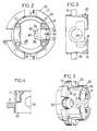
- Figures 2 to 5 show respectively in end view, in axial section along III-III, Figure 2, in partial longitudinal section along IV-IV, Figure 2 and in perspective view, a tubular interlayer forming part of the above transmission , insert established according to the invention.
- the electric retarder considered is of the type - known under the brand "FOCAL" - mounted, with a horizontal or substantially horizontal axis, in overhang on the output of a gearbox casing 1.
- This retarder comprises an inductor stator 2 and an induced rotor 3.
- the stator 2 comprises a flange of substantially annular shape 4 which carries a ring of coils 5 in an even number arranged so as to form by their ends two annular suites of plane magnetic poles with alternating polarities gradually.
- the flange 4 is mounted on the box casing 1 -or more precisely on an intermediate frame 6 which is itself fitted against the flat front face of said casing 1- by means of a structure 7 in the form of a star or bell openwork and tubular shims 8.
- the rotor 3 comprises in turn two discs 9 own ferromagnetic material axially the stator frame and scrolling each facing a series of stator poles that they are separated by a small clearance or gap e.
- Each disc 9 is connected to a fixing ring 10 by a crown of curved arms 11 forming ventilation fins and the two rings 10 are bolted using bolt-nut systems 12 on an intermediate ring 13 to which we will return later.
- the central portion of the box mount 6 has the shape of a cylindrical nose 17 carrying, by means of an end bearing 18, a sleeve 19 whose outer axial end is extended radially by the flange 14 called in the this text "box flange".
- the other axial end of the sleeve 19 is internally fluted at 20 and is force-fitted onto the end piece 21 of the box, externally fluted at 22.
- This fitting is forcibly carried out to avoid any creation of play and it is then held by axial screwing in the end piece 21 with screws 23 whose heads are applied against a plate 24 which itself bears on the sleeve 19.
- the axial lengths of the nose 17 and of the sleeve 19 are relatively small and the flange 14 extends near the axial end of said nose 17.
- this particularly heavy and bulky intermediate plate is eliminated by replacing the assembly of said plate and of the usual cardan end flange with a tubular insert or single sleeve 25.
- the ring 13 above is part of this sleeve 25, and said sleeve 25 comprises two bores 26 themselves serving as bearings for two of the pins of the cross 27 included by the seal 15, pins designated by the reference 28 while the other two journals are designated by the reference 29.
- two coaxial openings 30 are hollowed out radially in the sleeve 25, the common axis of which is perpendicular to that of the two bearings 26, openings capable of delivering passage to special mounting pads 31 for the two pins 29 of the crosspiece.
- Each of these ears is hollowed out by at least one bore 32 suitable for receiving a bolt 12 for fixing the rotor rings 10, one end of this bore 32 being shaped according to a rectangle suitable for contiguously receiving a square section 33 (FIG. 1) of said bolt 12 for the purpose of angular blocking thereof.
- each of these positions can be carried out despite, on the one hand, the relatively small opening of the fork and, on the other hand, the relatively small internal diameter of the sleeve 25, - itself due to the relatively small diameter internal of the rotor rings 10- thanks to the games then reserved between the pins and their housings, which makes it possible to present the crosspiece at an angle for said positioning.
- Each special bearing 31, 34 is in the general form of a cylindrical pot which adjusts adjoiningly in the corresponding bearing 36 (FIG. 1) of the fork 35 or 26 (FIG. 2) of the sleeve 25, its axial end-of-travel position in this bearing being maintained by introduction of a circlip washer 37, 38 in a complementary groove hollowed out in said bearing.
- each pad is lined with needles or rollers as shown at 39 in Figure 1.
- each pad 31, 34 is pierced externally in its center by a threaded hole 40 facilitating its axial extraction, after disengagement of the corresponding circlip from its groove, making it possible to attach an extraction tool by screwing this tool in said hole.
- the transfer of the torques applied to the transmission shaft between the two parts 14 and 25 is advantageously carried out by jointing caps or parallelepipedic blocks 42 forming part of the flange 14 by complementary notches 43 hollowed out in the skirt of the sleeve 25.
- the box 1 is initially assumed to have its flange 14.
- the universal joint 15 is mounted in the intermediate sleeve 25 by successively introducing its cross 27 in the fork 35 stripped of its bearings 31, then said fork fitted with the cross still floating in the sleeve 25 stripped of its bearings 34.
- the assemblies of the different trunnions are completed in their bearings by coming to cover them axially by the corresponding bearings, through the appropriate openings 26, 30 of the sleeve, then by putting in place the circlips 37, 38 in the corresponding grooves.
- This transmission has the double advantage: - to be extremely short, the axial distance between the center of the spider 27 and the front face F of application of the intermediate sleeve 25 on the box flange 14 can be as small as 50 mm for an electric retarder whose outside diameter is of the order of 500 mm, - And be able to be used with an electric retarder of a type currently existing, that is to say having a relatively narrow central opening, the inside diameter of its rotor rings 10 can be as small as 180 mm.
- the only fixing elements required are the four screws housed in the bores 41 of the intermediate sleeve 25: in particular the proposed construction comprises fewer screwing members than that mentioned above for which the rotor rings are fixed on a tubular insert itself attached to the enlarged periphery of the box flange and for which the seal universal joint comprises a normal terminal flange directly fixed to said box flange.
- the invention is in no way limited to those of its modes of application and embodiments which have been more especially envisaged; on the contrary, it embraces all variants, in particular those where the transfer of the torques between the box flange 14 and the sleeve 25 would be ensured by complementary teeth provided respectively on these two parts, or even by simple screws or bolts, the diameters and / or numbers would be increased compared to those of the embodiment described above.
Landscapes
- Engineering & Computer Science (AREA)
- Mechanical Engineering (AREA)
- Transportation (AREA)
- General Engineering & Computer Science (AREA)
- Combustion & Propulsion (AREA)
- Chemical & Material Sciences (AREA)
- Power Engineering (AREA)
- Dynamo-Electric Clutches, Dynamo-Electric Brakes (AREA)
- Braking Arrangements (AREA)
- Braking Systems And Boosters (AREA)
- Electric Propulsion And Braking For Vehicles (AREA)
- Glass Compositions (AREA)
- Arrangement And Driving Of Transmission Devices (AREA)
Priority Applications (1)
| Application Number | Priority Date | Filing Date | Title |
|---|---|---|---|
| AT90402857T ATE87552T1 (de) | 1989-10-17 | 1990-10-12 | Getriebe fuer fahrzeuge mit elektrischer bremsvorrichtung. |
Applications Claiming Priority (2)
| Application Number | Priority Date | Filing Date | Title |
|---|---|---|---|
| FR8913560A FR2653075B1 (fr) | 1989-10-17 | 1989-10-17 | Perfectionnements aux transmissions de vehicules equipees de ralentisseurs electriques. |
| FR8913560 | 1989-10-17 |
Publications (2)
| Publication Number | Publication Date |
|---|---|
| EP0425338A1 true EP0425338A1 (de) | 1991-05-02 |
| EP0425338B1 EP0425338B1 (de) | 1993-03-31 |
Family
ID=9386482
Family Applications (1)
| Application Number | Title | Priority Date | Filing Date |
|---|---|---|---|
| EP90402857A Expired - Lifetime EP0425338B1 (de) | 1989-10-17 | 1990-10-12 | Getriebe für Fahrzeuge mit elektrischer Bremsvorrichtung |
Country Status (10)
| Country | Link |
|---|---|
| US (1) | US5115693A (de) |
| EP (1) | EP0425338B1 (de) |
| JP (1) | JPH03140627A (de) |
| KR (1) | KR910007718A (de) |
| AT (1) | ATE87552T1 (de) |
| CA (1) | CA2027631A1 (de) |
| DE (1) | DE69001234T2 (de) |
| ES (1) | ES2039118T3 (de) |
| FR (1) | FR2653075B1 (de) |
| PT (1) | PT95605B (de) |
Families Citing this family (8)
| Publication number | Priority date | Publication date | Assignee | Title |
|---|---|---|---|---|
| FR2744679B1 (fr) * | 1996-02-12 | 1998-04-17 | Labavia | Transmission de vehicule equipee d'un ralentisseur electrique |
| DE19718896A1 (de) * | 1997-05-03 | 1998-11-05 | Man Nutzfahrzeuge Ag | Kreuzgelenkverbindung zwischen einer Gelenkwelle und einer Ab- oder Antriebswelle eines Getriebes, insbesondere eines Nutzfahrzeuges |
| US6231560B1 (en) * | 1999-02-10 | 2001-05-15 | Baxter International Inc | Method and apparatus for automatically controlling the level of medication |
| ATE300445T1 (de) * | 2000-02-02 | 2005-08-15 | Pacific Scient Electro Kinetic | Integrierter retarder und zubehör |
| US6723017B2 (en) | 2002-05-09 | 2004-04-20 | Visteon Global Technologies, Inc. | Differential assembly |
| FR2860356B1 (fr) * | 2003-09-26 | 2005-12-30 | Telma | Ralentisseur electromagnetique muni d'un support et d'un intercalaire integres |
| FR2860357B1 (fr) * | 2003-09-30 | 2005-12-30 | Telma | Ralentisseur electromagnetique muni d'un dispositif de fixation |
| CN101186183B (zh) * | 2007-12-20 | 2010-04-21 | 陈传松 | 电涡流缓速器 |
Citations (6)
| Publication number | Priority date | Publication date | Assignee | Title |
|---|---|---|---|---|
| GB655168A (en) * | 1947-02-06 | 1951-07-11 | Gaston Robert Bouchard | Improvements in driving arrangements for driving and steering wheels on motor vehicles |
| FR2247846A1 (de) * | 1973-10-15 | 1975-05-09 | Labavia | |
| US4128147A (en) * | 1976-11-30 | 1978-12-05 | Antonio Lafuente Ruberte | Vehicle speed reducer or eddy current brake |
| US4138863A (en) * | 1977-08-25 | 1979-02-13 | Rockford Acromatic Products Co. | Universal joint cross with adjustable bearing cups |
| EP0094468A1 (de) * | 1982-05-14 | 1983-11-23 | Messerschmitt-Bölkow-Blohm Gesellschaft mit beschränkter Haftung | Kardangelenkverbindung |
| GB2122035A (en) * | 1982-06-17 | 1984-01-04 | Labavia | Improvements to electric retarders |
Family Cites Families (5)
| Publication number | Priority date | Publication date | Assignee | Title |
|---|---|---|---|---|
| US1746325A (en) * | 1926-01-14 | 1930-02-11 | Reo Motor Car Co | Universal-joint construction |
| US1908086A (en) * | 1927-12-10 | 1933-05-09 | Leonard H Mattingly | Method of making a universal joint |
| FR1595117A (de) * | 1968-01-17 | 1970-06-08 | ||
| FR2526101B1 (de) * | 1982-04-30 | 1987-03-20 | Nacam | |
| FR2627913B1 (fr) * | 1988-02-25 | 1992-02-07 | Labavia | Ralentisseur electromagnetique, moyens d'alimentation associes et application a un vehicule |
-
1989
- 1989-10-17 FR FR8913560A patent/FR2653075B1/fr not_active Expired - Fee Related
-
1990
- 1990-10-11 US US07/595,851 patent/US5115693A/en not_active Expired - Fee Related
- 1990-10-12 EP EP90402857A patent/EP0425338B1/de not_active Expired - Lifetime
- 1990-10-12 AT AT90402857T patent/ATE87552T1/de not_active IP Right Cessation
- 1990-10-12 ES ES199090402857T patent/ES2039118T3/es not_active Expired - Lifetime
- 1990-10-12 DE DE9090402857T patent/DE69001234T2/de not_active Expired - Fee Related
- 1990-10-15 CA CA002027631A patent/CA2027631A1/en not_active Abandoned
- 1990-10-16 PT PT95605A patent/PT95605B/pt not_active IP Right Cessation
- 1990-10-16 KR KR1019900016485A patent/KR910007718A/ko not_active Ceased
- 1990-10-17 JP JP2278853A patent/JPH03140627A/ja active Pending
Patent Citations (6)
| Publication number | Priority date | Publication date | Assignee | Title |
|---|---|---|---|---|
| GB655168A (en) * | 1947-02-06 | 1951-07-11 | Gaston Robert Bouchard | Improvements in driving arrangements for driving and steering wheels on motor vehicles |
| FR2247846A1 (de) * | 1973-10-15 | 1975-05-09 | Labavia | |
| US4128147A (en) * | 1976-11-30 | 1978-12-05 | Antonio Lafuente Ruberte | Vehicle speed reducer or eddy current brake |
| US4138863A (en) * | 1977-08-25 | 1979-02-13 | Rockford Acromatic Products Co. | Universal joint cross with adjustable bearing cups |
| EP0094468A1 (de) * | 1982-05-14 | 1983-11-23 | Messerschmitt-Bölkow-Blohm Gesellschaft mit beschränkter Haftung | Kardangelenkverbindung |
| GB2122035A (en) * | 1982-06-17 | 1984-01-04 | Labavia | Improvements to electric retarders |
Also Published As
| Publication number | Publication date |
|---|---|
| US5115693A (en) | 1992-05-26 |
| CA2027631A1 (en) | 1991-04-18 |
| ES2039118T3 (es) | 1993-08-16 |
| DE69001234T2 (de) | 1993-09-23 |
| KR910007718A (ko) | 1991-05-30 |
| JPH03140627A (ja) | 1991-06-14 |
| DE69001234D1 (de) | 1993-05-06 |
| PT95605A (pt) | 1992-05-29 |
| EP0425338B1 (de) | 1993-03-31 |
| FR2653075B1 (fr) | 1992-01-24 |
| PT95605B (pt) | 1998-07-31 |
| ATE87552T1 (de) | 1993-04-15 |
| FR2653075A1 (fr) | 1991-04-19 |
Similar Documents
| Publication | Publication Date | Title |
|---|---|---|
| CA2725739C (fr) | Ensemble de roue et frein pour aeronef equipe d'un dispositif d'entrainement en rotation | |
| EP2982602B1 (de) | Drehmomentübertragung an das rad über die befestigungsbolzen der felge | |
| FR2665417A1 (fr) | Agencement d'appareillage rotatif pour trains d'atterrissage. | |
| EP0425338B1 (de) | Getriebe für Fahrzeuge mit elektrischer Bremsvorrichtung | |
| FR3055379A1 (fr) | Roue d'aeronef a boitier a roulements separable | |
| FR2781729A1 (fr) | Joint homocinetique dote de moyens de centrage et unite structurelle comprenant un tel joint | |
| CA1233994A (fr) | Moyeu de roue a reducteur integre | |
| EP0403714B1 (de) | Kraftfahrzeugantrieb mit elektrischen Bremsvorrichtungen | |
| EP0406110B1 (de) | Antriebsübertragung für ein Kfz mit elektromagnetischen Bremsvorrichtungen | |
| FR2529030A1 (fr) | Perfectionnements aux ralentisseurs electriques | |
| FR2689191A1 (fr) | Friction d'embrayage, notamment pour véhicule industriel. | |
| EP0789443B1 (de) | Fahrzeuggetriebe versehen mit einem elektrischen Retarder | |
| EP0789442B1 (de) | Fahrzeuggetriebe versehen mit einem elektrischen Retarder | |
| FR2597798A1 (fr) | Dispositif d'accouplement en rotation d'un moyeu de roue | |
| EP0789444B1 (de) | Kraftfahrzeuggetriebe, versehen mit einem elektrischen Retarder | |
| FR2548595A1 (fr) | Ensemble de moyeu de roue motrice de vehicule | |
| EP1028263A1 (de) | Kupplung für Pumpe und Motor | |
| FR3068741A1 (fr) | Arbre d’entrainement pour une turbomachine | |
| EP4126663B1 (de) | Flugzeugrad mit antriebslaschen | |
| EP0340058B1 (de) | Bremse mit mehreren Scheiben | |
| EP0406085A1 (de) | Kreuzgelenk geringer Länge und Kraftfahrzeuggetriebe, versehen mit demselben und vorzugsweise versehen mit einem elektrischen Retarder | |
| FR2568962A1 (fr) | Transmission a joint de cardan perfectionnee | |
| FR2860357A1 (fr) | Ralentisseur electromagnetique muni d'un dispositif de fixation | |
| EP0292360A2 (de) | Sattelscheibenbremse aus einem Material mit schwachem Widerstand gegen Druck | |
| FR2710956A1 (fr) | Cartouche d'embrayage compacte et amovible. |
Legal Events
| Date | Code | Title | Description |
|---|---|---|---|
| PUAI | Public reference made under article 153(3) epc to a published international application that has entered the european phase |
Free format text: ORIGINAL CODE: 0009012 |
|
| AK | Designated contracting states |
Kind code of ref document: A1 Designated state(s): AT BE CH DE ES GB IT LI NL SE |
|
| 17P | Request for examination filed |
Effective date: 19910628 |
|
| 17Q | First examination report despatched |
Effective date: 19920327 |
|
| GRAA | (expected) grant |
Free format text: ORIGINAL CODE: 0009210 |
|
| AK | Designated contracting states |
Kind code of ref document: B1 Designated state(s): AT BE CH DE ES GB IT LI NL SE |
|
| REF | Corresponds to: |
Ref document number: 87552 Country of ref document: AT Date of ref document: 19930415 Kind code of ref document: T |
|
| GBT | Gb: translation of ep patent filed (gb section 77(6)(a)/1977) |
Effective date: 19930329 |
|
| REF | Corresponds to: |
Ref document number: 69001234 Country of ref document: DE Date of ref document: 19930506 |
|
| ITF | It: translation for a ep patent filed | ||
| REG | Reference to a national code |
Ref country code: ES Ref legal event code: FG2A Ref document number: 2039118 Country of ref document: ES Kind code of ref document: T3 |
|
| PLBE | No opposition filed within time limit |
Free format text: ORIGINAL CODE: 0009261 |
|
| STAA | Information on the status of an ep patent application or granted ep patent |
Free format text: STATUS: NO OPPOSITION FILED WITHIN TIME LIMIT |
|
| 26N | No opposition filed | ||
| EAL | Se: european patent in force in sweden |
Ref document number: 90402857.8 |
|
| PGFP | Annual fee paid to national office [announced via postgrant information from national office to epo] |
Ref country code: SE Payment date: 19970923 Year of fee payment: 8 Ref country code: AT Payment date: 19970923 Year of fee payment: 8 |
|
| PGFP | Annual fee paid to national office [announced via postgrant information from national office to epo] |
Ref country code: DE Payment date: 19970924 Year of fee payment: 8 |
|
| PGFP | Annual fee paid to national office [announced via postgrant information from national office to epo] |
Ref country code: NL Payment date: 19970925 Year of fee payment: 8 Ref country code: GB Payment date: 19970925 Year of fee payment: 8 |
|
| PGFP | Annual fee paid to national office [announced via postgrant information from national office to epo] |
Ref country code: CH Payment date: 19970926 Year of fee payment: 8 |
|
| PGFP | Annual fee paid to national office [announced via postgrant information from national office to epo] |
Ref country code: BE Payment date: 19971013 Year of fee payment: 8 |
|
| PGFP | Annual fee paid to national office [announced via postgrant information from national office to epo] |
Ref country code: ES Payment date: 19971020 Year of fee payment: 8 |
|
| PG25 | Lapsed in a contracting state [announced via postgrant information from national office to epo] |
Ref country code: GB Free format text: LAPSE BECAUSE OF NON-PAYMENT OF DUE FEES Effective date: 19981012 Ref country code: AT Free format text: LAPSE BECAUSE OF NON-PAYMENT OF DUE FEES Effective date: 19981012 |
|
| PG25 | Lapsed in a contracting state [announced via postgrant information from national office to epo] |
Ref country code: SE Free format text: LAPSE BECAUSE OF NON-PAYMENT OF DUE FEES Effective date: 19981013 Ref country code: ES Free format text: LAPSE BECAUSE OF THE APPLICANT RENOUNCES Effective date: 19981013 |
|
| PG25 | Lapsed in a contracting state [announced via postgrant information from national office to epo] |
Ref country code: LI Free format text: LAPSE BECAUSE OF NON-PAYMENT OF DUE FEES Effective date: 19981031 Ref country code: CH Free format text: LAPSE BECAUSE OF NON-PAYMENT OF DUE FEES Effective date: 19981031 Ref country code: BE Free format text: LAPSE BECAUSE OF NON-PAYMENT OF DUE FEES Effective date: 19981031 |
|
| BERE | Be: lapsed |
Owner name: LABAVIA S.G.E. Effective date: 19981031 |
|
| PG25 | Lapsed in a contracting state [announced via postgrant information from national office to epo] |
Ref country code: NL Free format text: LAPSE BECAUSE OF NON-PAYMENT OF DUE FEES Effective date: 19990501 |
|
| GBPC | Gb: european patent ceased through non-payment of renewal fee |
Effective date: 19981012 |
|
| REG | Reference to a national code |
Ref country code: CH Ref legal event code: PL |
|
| EUG | Se: european patent has lapsed |
Ref document number: 90402857.8 |
|
| NLV4 | Nl: lapsed or anulled due to non-payment of the annual fee |
Effective date: 19990501 |
|
| PG25 | Lapsed in a contracting state [announced via postgrant information from national office to epo] |
Ref country code: DE Free format text: LAPSE BECAUSE OF NON-PAYMENT OF DUE FEES Effective date: 19990803 |
|
| REG | Reference to a national code |
Ref country code: ES Ref legal event code: FD2A Effective date: 20001009 |
|
| PG25 | Lapsed in a contracting state [announced via postgrant information from national office to epo] |
Ref country code: IT Free format text: LAPSE BECAUSE OF NON-PAYMENT OF DUE FEES;WARNING: LAPSES OF ITALIAN PATENTS WITH EFFECTIVE DATE BEFORE 2007 MAY HAVE OCCURRED AT ANY TIME BEFORE 2007. THE CORRECT EFFECTIVE DATE MAY BE DIFFERENT FROM THE ONE RECORDED. Effective date: 20051012 |