EP0428291A2 - Schwingungsdämpfungsdichtung für Plattenantrieb - Google Patents
Schwingungsdämpfungsdichtung für Plattenantrieb Download PDFInfo
- Publication number
- EP0428291A2 EP0428291A2 EP90311844A EP90311844A EP0428291A2 EP 0428291 A2 EP0428291 A2 EP 0428291A2 EP 90311844 A EP90311844 A EP 90311844A EP 90311844 A EP90311844 A EP 90311844A EP 0428291 A2 EP0428291 A2 EP 0428291A2
- Authority
- EP
- European Patent Office
- Prior art keywords
- disk drive
- cover
- base
- disk
- drive
- Prior art date
- Legal status (The legal status is an assumption and is not a legal conclusion. Google has not performed a legal analysis and makes no representation as to the accuracy of the status listed.)
- Granted
Links
Images

Classifications
-
- G—PHYSICS
- G11—INFORMATION STORAGE
- G11B—INFORMATION STORAGE BASED ON RELATIVE MOVEMENT BETWEEN RECORD CARRIER AND TRANSDUCER
- G11B25/00—Apparatus characterised by the shape of record carrier employed but not specific to the method of recording or reproducing, e.g. dictating apparatus; Combinations of such apparatus
- G11B25/04—Apparatus characterised by the shape of record carrier employed but not specific to the method of recording or reproducing, e.g. dictating apparatus; Combinations of such apparatus using flat record carriers, e.g. disc, card
- G11B25/043—Apparatus characterised by the shape of record carrier employed but not specific to the method of recording or reproducing, e.g. dictating apparatus; Combinations of such apparatus using flat record carriers, e.g. disc, card using rotating discs
-
- G—PHYSICS
- G11—INFORMATION STORAGE
- G11B—INFORMATION STORAGE BASED ON RELATIVE MOVEMENT BETWEEN RECORD CARRIER AND TRANSDUCER
- G11B33/00—Constructional parts, details or accessories not provided for in the other groups of this subclass
- G11B33/02—Cabinets; Cases; Stands; Disposition of apparatus therein or thereon
- G11B33/08—Insulation or absorption of undesired vibrations or sounds
-
- G—PHYSICS
- G11—INFORMATION STORAGE
- G11B—INFORMATION STORAGE BASED ON RELATIVE MOVEMENT BETWEEN RECORD CARRIER AND TRANSDUCER
- G11B33/00—Constructional parts, details or accessories not provided for in the other groups of this subclass
- G11B33/14—Reducing influence of physical parameters, e.g. temperature change, moisture, dust
Definitions
- This invention relates to the sealing of a hard magnetic disk drive enclosure.
- Disk drive enclosures are sealed to prevent the entry of contamination that would damage the internal head/disk interface.
- Hard disk drives are manufactured in clean environments and are sealed prior to moving them into normal user environments.
- the internal disk parts such as the disk stack assembly and the moveable actuator which mounts the magnetic heads and which moves the magnetic heads over the surfaces of the disk, are usually assembled onto some form of a base which is part of the main frame of the disk drive. After all of the parts are in place, a protective cover is installed. Thereafter, the cover and the base are sealed to prevent the entry of contaminants into the enclosure.
- Disk drive structural parts are manufactured of materials that are elastic and substantially rigid with respect to the application to which they are put. Structural rigidity of the parts is needed to ensure adequate dimensional accuracy and stability. Unfortunately, the inherently poor damping qualities of these elastic parts cause head-to-disk positioning errors when the drive is subjected to vibrational inputs.
- the disk stack assembly which is rotatably mounted on a fixed spindle is often a significant source of input excitation energy that, combined with the undamped drive structure, is a frequent manufacturing problem.
- the drive is sealed by pressing the cover against a compliant gasket which is often made of an elastomeric material. This gasket is compressed between the cover and the base. This form of sealing poses several problems:
- Gaskets are difficult to clean adequately for use in the disk drive. Structural parts of the drive are usually cleaned in an aggressive solvent that cannot be used on the gasket material. Less effective, alternate cleaning processes usually are required for gaskets. Residual contamination on gaskets can cause damage to the delicate head/disk interface inside a disk drive and reduce the reliability of the disk drive.
- Gaskets of this type do not lend themselves to automated assembly processes, so usually they are manually placed into position. Because of this, and inherent defects in the compcsition and/or surface condition of gaskets and their mating surfaces, the consistency and degree of sealing that is achieved is often unsatisfactory.
- the cover when installed, is not pressed against the base.
- Either the cover or the base or both may have side walls, the ends of which are disposed in confronting, or adjacent, but not touching relationship.
- four posts are employed which are mounted at one end of each thereof on the base and which at each of their upper ends receive the top plate of the cover. These posts provide flexibility between the base and the top cover connections. They allow the base and the cover to assume minutely different physical dimensions without imposing any large stresses at the post interfaces.
- the posts are permanently attached to the base and the cover is fastened by screws to the top of each post as well as to the top of the disk spindle and the support for the magnetic head actuator suspension assembly.
- the drive is sealed by employing a viscoelastic tape seal which does not apply stress to the drive parts.
- the tape is pressed onto the cover and the base, bridging the gap therebetween in a substantially unstressed condition. Since there are nominally no initial stresses, there are no stress changes over time or temperature.
- the tape seal is intentionally made of a viscoelastic material which does not generate any significant stress on the drive parts as a result of stiffness changes with changes in temperature, as compressed gaskets do.
- a constraining layer a thin layer of stiff backing material such as aluminum
- a high degree of resonant damping is achieved in the overall drive structure. Relative motion between the cover and the base of the drive is damped by the viscoelastic coupling that the seal offers. This added damping greatly reduces the natural ringing of the structure as well as its sensitivity to vibration by sources such as the bearings in rotating disk stack assembly of the disk spindle in the drive.
- the tape seal is easily supplied. It can be supplied in roll form similar to ordinary pressure sensitive adhesive types of tapes and is dispensed directly against the drive surfaces that are being sealed. There is no need to preclean the tape prior to application to the drive surfaces since the adhesive side of the tape faces the interior of the drive, and any particles that might be present are held adhesively by the sticky viscoelastic material.
- Tape seals are easily automated for high volume manufacturing through the use of existing technology that has been developed for the packaging industry. The speed, consistency, and cost of this form of sealing is highly desirable in high volume, low cost disk drive manufacturing.
- Fig. 1 illustrates the best mode for practicing this invention presently known to the applicant. It will be appreciated, however, that this invention is not limited to the specific disk drive which is illustrated.
- the disk drive comprises a base or main frame 1 on which a disk spindle 2 is mounted.
- the base may be a plate, as shown, or may have sides and ends.
- a disk stack assembly 3, comprising individual disks 3a, is rotatably journaled on the disk spindle 2.
- This disk stack assembly is rctated at constant speed by a drive motor which is an integral part of the disk spindle.
- This invention is applicable to both linear or rotary actuator types of disk drives.
- the disk drive which is illustrated is of the rotary actuator type.
- An actuator spindle 4 is secured to the main frame or base 1 adjacent an edge of the disk stack assembly 3.
- An actuator bearing housing 5 is journaled on the actuator spindle 4 and mounts a plurality of actuator arms 6 each of which, in turn, mounts a flexure 7 each of which flexibly mounts a magnetic head 8 at its extremity.
- a magnetic head on the bottom arm on the bottom side of the bottom disk is a dedicated servo positioning head and the dedicated servo disk surface then is the bottom surface of the bottom disk on which the servo code defining the individual tracks is recorded.
- An electromagnetic driver generally designated 9 is employed to drive the rotary actuator.
- the electromagnetic driver 9 comprises a coil 10 secured to the bearing housing 5 and a permanent magnet structure, comprising permanent magnets 11, one of which is illustrated disposed below the coil 10 and another, not illustrated, is positioned above the coil 10.
- the coil 10 when reversibly energized with direct current moves the actuator arms 6 and the magnetic heads 8 in one direction or another in an arc about the actuator spindle 4, radially over the disk surfaces. In this manner, track seeking is accomplished and track following achieved whenever a selected track is found.
- a cover 12 having a top plate 13 and depending sides and ends 14, encloses the disk drive assembly.
- this cover 12 is elevated above the disk drive so that the disk drive components may be visible.
- the interface of the top plate 13 of the cover 12 seats upon the upper ends of posts 15 which are secured to the base plate or main frame 1 and which project upwardly therefrom.
- Holes 16 through the upper plate 13 of the cover 12 are aligned with respective threaded holes 17 in the upper ends of the posts 15.
- the cover is secured to the upper ends of these posts by means of screws 18, only one of which is shown, which extend through the top plate 13 and individually thread into the adjacent threaded hole 17 in the upper end of each of the posts 15.
- the lengths of the posts 15 and the spindles 2 and 4 are dimensioned with respect to the interface of the plate 13 so that all confronting face portions thereat make contact, without the need for deformation, when the cover 12 is positioned over the disk drive assembly. In this position the lower peripheral edge of the depending sides and ends 14 of the cover 12, does not touch the peripheral upper face portion of the base of the main frame 1. When the screws 18 and 19 are installed, the assembly is secured.
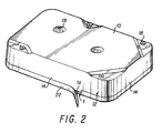
- a final seal between the main frame and the cover 12 is achieved by means of a viscoelastic tape 22, which is only fragmentarily shown in Fig. 1, having a surface coated with a pressure sensitive adhesive which provides a peripheral seal at a gap 1a, Fig. 2, between the oover 12 and the main frame 1.
- the tape 22 can have a relativeIy high sheer strength, and provide resistance to relative vibrational movement between the adjacent section of the ccver 12 and the base 1.
- the seal between the base 1 and the cover 12 of a disk drive is an elastic gasket that is compressed in the gap between the base 1 and the cover 12. This creates an initial stress in the drive base 1 and cover 12 which is usually present at the time the data tracks are first recorded on the disks of the disk stack. Over a period of time, and especially in the presence of elevated temperatures, the gasket material relaxes and the pressure within the gasket material reduces, also reducing the force that it exerts upon the base 1 and the cover 12. Such force reductions typically cause minute dimensional changes and distortions of the disk drive struotural members and significant data head-to-track positioning errors may result.
- the tape seal solves this problem because it does not impose an initially distorting stress on the base or cover and because of the viscous property of the pressure sensitive adhesive, it also does not impose stress due to aging or due to temperature variations of the disk drive.
- the tape seal therefore, in this respect, is a simple, low cost sealing solution that does not cause dimensional distorticns within the disk drive over time and temperature.
- the tape seal has an additional important function in that it provides a high degree of resonant damping in the overall drive structure. This is achieved, according to one embodiment of this invention, by adding a constraining layer, e.g., a thin layer of stiff backing material such as aluminum, annealed aluminum being preferred, to the viscoelastic seal material, which adds stiffness to the outer face of the tape seal and significant shear energy damping of base-to-cover vibrations.
- This thin layer is applied to the outer face of the tape, the inner face of which is coated with a pressure sensitive adhesive of a type which has effective damping in the temperature range environment of the disk drive.
- the use of an aluminum layer or film on the tape is exemplary. Any form of tape whether of single layer or multiple layer, having energy absorbing properties, is contemplated herein.
- the use of the tape seal permits automation for high volume manufacturing.
- the tape seal can be applied with the required pressure, or, once applied to the drive, a roller may be pressed against the tape seal around the disk drive to provide the proper sealing pressure.
- Figures 1 and 2 depict a disk drive having a flat base and a cover 12 with depending sides and ends 14, it will be appreciated that other cover/base configurations may be used in which the base itself has the side portions and the cover may be a flat plate or the base and the cover may have side portions which confront and form a gap 1a in a position intermediate the base 1 and the cover top plate 13.
- posts 15 in establishing the positional relationship between the cover 12 and the base 1 is exemplary.
- the use of posts is advantageous in the sense that they provide a degree of flexibility in the structural relationship between the cover 12 and the base 1. Any means for establishing the structural relationship between the cover 12 and the base 1, forming the gap 1a and providing a seal which does not stress the disk drive, may be practiced within the spirit and scope of this invention. In any such installation, however, a degree of flexibility between the cover and the base is desirable to minimize, if not entirely eliminate, the possibility of slippage at the joints or interfaces among these major parts of the disk drive structure. Additionally, such flexible structural provision and positioning of the major parts, permits the use of tape for the seal, which can damp ringing in the structure.
- the tape seal of this invention is applicable in all types of disk drive.
Landscapes
- Moving Of Heads (AREA)
- Gasket Seals (AREA)
Applications Claiming Priority (2)
| Application Number | Priority Date | Filing Date | Title |
|---|---|---|---|
| US07/434,653 US5021905A (en) | 1989-11-13 | 1989-11-13 | Disk drive enclosure for minimizing stresses and a vibration damping seal therefor |
| US434653 | 1999-11-05 |
Publications (3)
| Publication Number | Publication Date |
|---|---|
| EP0428291A2 true EP0428291A2 (de) | 1991-05-22 |
| EP0428291A3 EP0428291A3 (en) | 1992-01-15 |
| EP0428291B1 EP0428291B1 (de) | 1996-04-03 |
Family
ID=23725096
Family Applications (1)
| Application Number | Title | Priority Date | Filing Date |
|---|---|---|---|
| EP90311844A Expired - Lifetime EP0428291B1 (de) | 1989-11-13 | 1990-10-29 | Schwingungsdämpfungsdichtung für Plattenantrieb |
Country Status (6)
| Country | Link |
|---|---|
| US (1) | US5021905A (de) |
| EP (1) | EP0428291B1 (de) |
| JP (1) | JPH03171491A (de) |
| BR (1) | BR9004814A (de) |
| CA (1) | CA2021358C (de) |
| DE (1) | DE69026338T2 (de) |
Cited By (2)
| Publication number | Priority date | Publication date | Assignee | Title |
|---|---|---|---|---|
| DE4120271A1 (de) * | 1990-06-20 | 1992-01-09 | Tokico Ltd | Magnetplattengeraet |
| EP0739013A4 (de) * | 1994-10-06 | 1996-12-27 | Hitachi Ltd | Magnetplattengerät |
Families Citing this family (56)
| Publication number | Priority date | Publication date | Assignee | Title |
|---|---|---|---|---|
| US5276577A (en) * | 1989-04-17 | 1994-01-04 | International Business Machines Corporation | Head-disk enclosure seal for magnetic disk storage device |
| JPH04195988A (ja) * | 1990-11-28 | 1992-07-15 | Nikon Corp | 光学式情報媒体のドライブ装置 |
| US5875067A (en) * | 1991-03-22 | 1999-02-23 | Seagate Technology, Inc. | Acoustic isolator for a disc drive assembly |
| JPH0810909Y2 (ja) * | 1991-05-31 | 1996-03-29 | ティアック株式会社 | ハードディスク装置 |
| US5270887A (en) * | 1991-12-04 | 1993-12-14 | Western Digital Corporation | Compact disk drive head disk assembly with conformable tape seal |
| US5243495A (en) * | 1992-03-20 | 1993-09-07 | Digital Equipment Corporation | Removable enclosure housing a rigid disk drive |
| US5223996A (en) * | 1992-03-20 | 1993-06-29 | Digital Equipment Corporation | Combined shock mount frame and seal for a rigid disk drive |
| US5491607A (en) * | 1992-04-14 | 1996-02-13 | Abekas Video Systems, Inc. | Method of modifying a disk drive from serial to parallel operation |
| US5366200A (en) * | 1992-09-29 | 1994-11-22 | Scura John E | Shock mount assembly |
| JP3129894B2 (ja) * | 1992-10-26 | 2001-01-31 | 富士通株式会社 | ディスク記憶システム |
| US5357386A (en) * | 1992-11-13 | 1994-10-18 | Seagate Technology, Inc. | Disc drive with head/disc assembly having sealed connectors |
| JP3320478B2 (ja) * | 1993-02-23 | 2002-09-03 | 住友スリーエム株式会社 | 粘弾性体を備えた積層体製品の製造方法及び制振材 |
| US5550694A (en) * | 1993-07-12 | 1996-08-27 | Western Digital Corporation | Magnetic memory disk storage system |
| US5825585A (en) * | 1993-11-03 | 1998-10-20 | Maxtor Corporation | Laterally constrained and damped mount for a hard disk drive |
| KR0124990B1 (ko) * | 1993-12-01 | 1997-11-28 | 김광호 | 하드디스크 드라이브의 진동이나 소음감쇄 및 외부충격 완화용 지지장치 |
| US5598306A (en) * | 1994-07-29 | 1997-01-28 | International Business Machines Corporation | Damping post for reducing acoustic noise in a disk drive |
| US6108163A (en) * | 1994-10-12 | 2000-08-22 | International Business Machines Corporation | Sensitive sensor internally mounted shock for a disk drive |
| US5864441A (en) * | 1994-12-08 | 1999-01-26 | International Business Machines Corporation | Actuator mounting apparatus for top-down data storage system assembly |
| MY114912A (en) | 1994-12-22 | 2003-02-28 | Ibm | Removable electronic subassembly with a compressible shock absorbing device |
| US5725931A (en) * | 1995-11-03 | 1998-03-10 | Minnesota Mining And Manufacturing Company | Constrained layer damper with slit(s) and/or cutout(s) |
| US5696648A (en) * | 1996-07-08 | 1997-12-09 | Samsung Electronics Co., Ltd. | Sealing device for a hard disk drive |
| US6510021B1 (en) * | 1996-06-03 | 2003-01-21 | Seagate Technology Llc | Mechanical isolation for a disc drive spindle motor |
| US5858509A (en) * | 1996-11-15 | 1999-01-12 | Digital Equipment Corporation | Attenuating vibrations in a mounting shelf for multiple disk drives |
| US5926366A (en) * | 1996-11-15 | 1999-07-20 | Digital Equipment Corporation | Tab and slot disk drive vibration reduction structure |
| US6185807B1 (en) | 1997-01-28 | 2001-02-13 | Seagate Technology Llc | Component sealing system |
| JP3470568B2 (ja) * | 1997-09-26 | 2003-11-25 | 富士通株式会社 | ボイスコイルモータを備えた情報記録装置およびそのカバー |
| US6324054B1 (en) | 1998-01-26 | 2001-11-27 | Seagate Technology Llc | Wrap around shock absorber for disc drives |
| JPH11232833A (ja) | 1998-02-10 | 1999-08-27 | Fujitsu Ltd | 記録ディスク装置およびそのカバーシール |
| US6704161B1 (en) | 1998-11-06 | 2004-03-09 | Samsung Electronics Co. Ltd. | Shock protection skin bumper for a hard disk drive |
| US6417986B1 (en) | 1998-11-16 | 2002-07-09 | Samsung Electronics Co., Ltd. | Impact guard for limiting hard disk movement |
| KR100295227B1 (ko) | 1998-11-17 | 2001-07-12 | 윤종용 | 하드디스크드라이브커버구조 |
| US6549372B1 (en) | 1998-12-15 | 2003-04-15 | Samsung Electronics Co., Ltd | Device for limiting head movement within a hard disk drive |
| JP2000339895A (ja) * | 1999-03-24 | 2000-12-08 | Nitto Denko Corp | 制振材およびそれを用いたヘッドサスペンション |
| JP2000291802A (ja) * | 1999-04-12 | 2000-10-20 | Kokoku Intech Co Ltd | ハードディスク装置用ガスケット |
| US6417994B1 (en) | 1999-04-22 | 2002-07-09 | Samsung Electronics, Co., Ltd. | Swage plate with protruded walls to increase retention torque in hard disk applications |
| US6674608B1 (en) * | 1999-05-07 | 2004-01-06 | Seagate Technologies Llc | Damped protective cover to improve disc drive acoustics |
| US6501614B1 (en) | 1999-08-19 | 2002-12-31 | Samsung Electronics Co., Ltd. | Acoustic insulator for controlling noise generated in a mass storage device |
| US6744597B2 (en) | 1999-10-29 | 2004-06-01 | Samsung Electronics Co., Ltd. | Dynamic absorber for an actuator arm in a disk drive |
| US6430000B1 (en) | 2000-04-13 | 2002-08-06 | General Dynamics Information Systems, Inc. | Hermetically sealed plural disk drive housing |
| US6947252B2 (en) | 2000-05-10 | 2005-09-20 | Samsung Electronics Co., Ltd. | Wave stringer for controlling acoustic noise and shock vibration in a storage device |
| US6954328B2 (en) | 2001-02-09 | 2005-10-11 | Seagate Technology, Llc | Multi-layer housing structure with tuned layers using hypothetical modeling |
| US6590738B2 (en) | 2001-03-01 | 2003-07-08 | Samsung Electronics Co., Ltd. | Particle removal device in a hard disk drive |
| US6762908B2 (en) | 2001-06-18 | 2004-07-13 | Samsung Electronics Co., Ltd. | Air razor and disk limiter for a hard disk drive |
| US20030091777A1 (en) * | 2001-08-14 | 2003-05-15 | Peter Jones | Clean release tape for EMI shielding |
| CA2427287C (en) * | 2002-12-19 | 2011-01-25 | Bruce D. Johnson | Cable clamp |
| TW587823U (en) * | 2002-12-31 | 2004-05-11 | Asustek Comp Inc | Low-noise compact disk drive |
| KR100513730B1 (ko) * | 2003-07-11 | 2005-09-08 | 삼성전자주식회사 | 디스크 드라이브용 마운팅 패드 |
| JP2005149574A (ja) * | 2003-11-12 | 2005-06-09 | Shinka Jitsugyo Kk | 磁気ディスクドライブ装置及び磁気ディスクドライブ装置の製造方法 |
| JP2005149651A (ja) * | 2003-11-18 | 2005-06-09 | Shinka Jitsugyo Kk | 磁気ディスクドライブ装置 |
| USD514564S1 (en) * | 2004-04-20 | 2006-02-07 | Kabushiki Kaisha Toshiba | Hard disk drive |
| USD512061S1 (en) * | 2004-04-20 | 2005-11-29 | Kabushiki Kaisha Toshiba | Hard disk drive |
| US8059364B1 (en) | 2004-05-04 | 2011-11-15 | Maxtor Corporation | Hermetically sealed connector interface |
| JP4624209B2 (ja) * | 2005-08-09 | 2011-02-02 | ヒタチグローバルストレージテクノロジーズネザーランドビーブイ | 磁気ディスク装置 |
| US8351150B2 (en) * | 2009-12-02 | 2013-01-08 | Hgst, Netherlands B.V. | Isolating unstable air pressure in a hard disk drive (HDD) |
| US8873231B2 (en) | 2010-12-23 | 2014-10-28 | HGST Netherlands B.V. | Electronic device enclosure configured to shield against electromagnetic interference |
| CN113002881A (zh) * | 2019-05-13 | 2021-06-22 | 宋局 | 一种物流封装机器人用升降装置 |
Family Cites Families (10)
| Publication number | Priority date | Publication date | Assignee | Title |
|---|---|---|---|---|
| US3925584A (en) * | 1972-08-24 | 1975-12-09 | Daiichi Seiyaku Co | Adhesive seal and tape for sealing |
| US4092687A (en) * | 1976-09-07 | 1978-05-30 | Sycor, Inc. | Disc file assembly |
| GB2030991B (en) * | 1977-02-09 | 1982-11-24 | Nitto Electric Ind Co | Heat activatable pressuresensitive adhesive tape of sheet |
| US4249221A (en) * | 1979-04-23 | 1981-02-03 | Sli Industries, Inc. | Method and apparatus for preventing contamination of a rotating magnetic disc |
| US4491888A (en) * | 1982-06-28 | 1985-01-01 | Atasi Corporation | Memory storage apparatus having vibration-dampened base plate arrangement |
| JPS6325877A (ja) * | 1986-07-17 | 1988-02-03 | Victor Co Of Japan Ltd | デイスク駆動装置用筐体 |
| US5060095A (en) * | 1989-01-31 | 1991-10-22 | International Business Machines Corporation | Head-disk enclosure assembly for a magnetic disk storage device |
| US5081552A (en) * | 1989-01-31 | 1992-01-14 | International Business Machines Corporation | Rigid magnetic disk drive head disk assembly and enclosure structure |
| JPH02292791A (ja) * | 1989-04-17 | 1990-12-04 | Internatl Business Mach Corp <Ibm> | 磁気デイスク駆動装置 |
| US5029027A (en) * | 1989-11-13 | 1991-07-02 | Hewlett-Packard Company | Thermally predictable disk drive mechanism |
-
1989
- 1989-11-13 US US07/434,653 patent/US5021905A/en not_active Expired - Fee Related
-
1990
- 1990-07-17 CA CA002021358A patent/CA2021358C/en not_active Expired - Fee Related
- 1990-09-20 BR BR909004814A patent/BR9004814A/pt not_active Application Discontinuation
- 1990-10-29 DE DE69026338T patent/DE69026338T2/de not_active Expired - Fee Related
- 1990-10-29 EP EP90311844A patent/EP0428291B1/de not_active Expired - Lifetime
- 1990-11-13 JP JP2306948A patent/JPH03171491A/ja active Pending
Cited By (3)
| Publication number | Priority date | Publication date | Assignee | Title |
|---|---|---|---|---|
| DE4120271A1 (de) * | 1990-06-20 | 1992-01-09 | Tokico Ltd | Magnetplattengeraet |
| EP0739013A4 (de) * | 1994-10-06 | 1996-12-27 | Hitachi Ltd | Magnetplattengerät |
| US6052255A (en) * | 1994-10-06 | 2000-04-18 | Hitachi, Ltd. | Magnetic disk unit having anti-impact arrangement |
Also Published As
| Publication number | Publication date |
|---|---|
| US5021905A (en) | 1991-06-04 |
| JPH03171491A (ja) | 1991-07-24 |
| DE69026338D1 (de) | 1996-05-09 |
| CA2021358A1 (en) | 1991-05-14 |
| EP0428291A3 (en) | 1992-01-15 |
| EP0428291B1 (de) | 1996-04-03 |
| BR9004814A (pt) | 1991-09-10 |
| CA2021358C (en) | 1995-08-29 |
| DE69026338T2 (de) | 1996-08-14 |
Similar Documents
| Publication | Publication Date | Title |
|---|---|---|
| CA2021358C (en) | Vibration damping disk drive seal | |
| US5270887A (en) | Compact disk drive head disk assembly with conformable tape seal | |
| US5223996A (en) | Combined shock mount frame and seal for a rigid disk drive | |
| US5696648A (en) | Sealing device for a hard disk drive | |
| US5233491A (en) | Disc drive with snap-fit seal | |
| JPS6325877A (ja) | デイスク駆動装置用筐体 | |
| US6175469B1 (en) | Disc drive magnet housing electro mechanical resonance dampening system | |
| US5029027A (en) | Thermally predictable disk drive mechanism | |
| US5862020A (en) | Hard disk driving apparatus using surface-treating method | |
| JPH07211044A (ja) | 磁気ディスク駆動装置の密閉構造 | |
| US7355811B1 (en) | Hermetically sealed housing with interior capture plate | |
| US6961215B2 (en) | Disk drive clamp for clamping disks to spindle motor with elastic portion and coated contact portion | |
| JPH04263187A (ja) | ディスク型記録装置およびその組立方法 | |
| US20050099734A1 (en) | Distributed damper for data storage devices | |
| US7733599B2 (en) | Structure to prevent deformation of magnetic disk device housing | |
| JPH04184758A (ja) | ディスク駆動装置 | |
| JPS62222475A (ja) | 情報記憶媒体 | |
| KR100375140B1 (ko) | 하드디스크드라이브의커버밀봉장치 | |
| JPH03203869A (ja) | 磁気ディスク装置の磁気ヘッドキャリッジ | |
| JPS61211887A (ja) | ヘツド装置 | |
| JP2001184835A (ja) | 磁気ディスク装置 | |
| JPH02201790A (ja) | 磁気ディスク装置 | |
| KR980011326A (ko) | 하드디스크 드라이브의 가요성 인쇄회로 고정장치 | |
| KR980011395A (ko) | 하드 디스크 드라이브의 가요성 인쇄회로 고정장치 | |
| JPH04119572A (ja) | 磁気ヘッド位置決め機構及び磁気回路 |
Legal Events
| Date | Code | Title | Description |
|---|---|---|---|
| PUAI | Public reference made under article 153(3) epc to a published international application that has entered the european phase |
Free format text: ORIGINAL CODE: 0009012 |
|
| AK | Designated contracting states |
Kind code of ref document: A2 Designated state(s): DE FR GB IT |
|
| PUAL | Search report despatched |
Free format text: ORIGINAL CODE: 0009013 |
|
| AK | Designated contracting states |
Kind code of ref document: A3 Designated state(s): DE FR GB IT |
|
| 17P | Request for examination filed |
Effective date: 19920611 |
|
| 17Q | First examination report despatched |
Effective date: 19940407 |
|
| GRAH | Despatch of communication of intention to grant a patent |
Free format text: ORIGINAL CODE: EPIDOS IGRA |
|
| GRAA | (expected) grant |
Free format text: ORIGINAL CODE: 0009210 |
|
| AK | Designated contracting states |
Kind code of ref document: B1 Designated state(s): DE FR GB IT |
|
| REF | Corresponds to: |
Ref document number: 69026338 Country of ref document: DE Date of ref document: 19960509 |
|
| ET | Fr: translation filed | ||
| ITF | It: translation for a ep patent filed | ||
| PGFP | Annual fee paid to national office [announced via postgrant information from national office to epo] |
Ref country code: FR Payment date: 19960913 Year of fee payment: 7 |
|
| PGFP | Annual fee paid to national office [announced via postgrant information from national office to epo] |
Ref country code: DE Payment date: 19960917 Year of fee payment: 7 |
|
| PGFP | Annual fee paid to national office [announced via postgrant information from national office to epo] |
Ref country code: GB Payment date: 19960925 Year of fee payment: 7 |
|
| PLBE | No opposition filed within time limit |
Free format text: ORIGINAL CODE: 0009261 |
|
| STAA | Information on the status of an ep patent application or granted ep patent |
Free format text: STATUS: NO OPPOSITION FILED WITHIN TIME LIMIT |
|
| 26N | No opposition filed | ||
| PG25 | Lapsed in a contracting state [announced via postgrant information from national office to epo] |
Ref country code: GB Free format text: LAPSE BECAUSE OF NON-PAYMENT OF DUE FEES Effective date: 19971029 |
|
| PG25 | Lapsed in a contracting state [announced via postgrant information from national office to epo] |
Ref country code: FR Free format text: THE PATENT HAS BEEN ANNULLED BY A DECISION OF A NATIONAL AUTHORITY Effective date: 19971031 |
|
| GBPC | Gb: european patent ceased through non-payment of renewal fee |
Effective date: 19971029 |
|
| PG25 | Lapsed in a contracting state [announced via postgrant information from national office to epo] |
Ref country code: DE Free format text: LAPSE BECAUSE OF NON-PAYMENT OF DUE FEES Effective date: 19980701 |
|
| REG | Reference to a national code |
Ref country code: FR Ref legal event code: ST |
|
| PG25 | Lapsed in a contracting state [announced via postgrant information from national office to epo] |
Ref country code: IT Free format text: LAPSE BECAUSE OF NON-PAYMENT OF DUE FEES Effective date: 20051029 |