EP0429058A2 - Elektrisches Fahrzeug - Google Patents
Elektrisches Fahrzeug Download PDFInfo
- Publication number
- EP0429058A2 EP0429058A2 EP90122175A EP90122175A EP0429058A2 EP 0429058 A2 EP0429058 A2 EP 0429058A2 EP 90122175 A EP90122175 A EP 90122175A EP 90122175 A EP90122175 A EP 90122175A EP 0429058 A2 EP0429058 A2 EP 0429058A2
- Authority
- EP
- European Patent Office
- Prior art keywords
- battery
- recharge
- generator
- section
- time
- Prior art date
- Legal status (The legal status is an assumption and is not a legal conclusion. Google has not performed a legal analysis and makes no representation as to the accuracy of the status listed.)
- Granted
Links
Images


Classifications
-
- B—PERFORMING OPERATIONS; TRANSPORTING
- B60—VEHICLES IN GENERAL
- B60W—CONJOINT CONTROL OF VEHICLE SUB-UNITS OF DIFFERENT TYPE OR DIFFERENT FUNCTION; CONTROL SYSTEMS SPECIALLY ADAPTED FOR HYBRID VEHICLES; ROAD VEHICLE DRIVE CONTROL SYSTEMS FOR PURPOSES NOT RELATED TO THE CONTROL OF A PARTICULAR SUB-UNIT
- B60W10/00—Conjoint control of vehicle sub-units of different type or different function
- B60W10/24—Conjoint control of vehicle sub-units of different type or different function including control of energy storage means
- B60W10/26—Conjoint control of vehicle sub-units of different type or different function including control of energy storage means for electrical energy, e.g. batteries or capacitors
-
- B—PERFORMING OPERATIONS; TRANSPORTING
- B60—VEHICLES IN GENERAL
- B60K—ARRANGEMENT OR MOUNTING OF PROPULSION UNITS OR OF TRANSMISSIONS IN VEHICLES; ARRANGEMENT OR MOUNTING OF PLURAL DIVERSE PRIME-MOVERS IN VEHICLES; AUXILIARY DRIVES FOR VEHICLES; INSTRUMENTATION OR DASHBOARDS FOR VEHICLES; ARRANGEMENTS IN CONNECTION WITH COOLING, AIR INTAKE, GAS EXHAUST OR FUEL SUPPLY OF PROPULSION UNITS IN VEHICLES
- B60K6/00—Arrangement or mounting of plural diverse prime-movers for mutual or common propulsion, e.g. hybrid propulsion systems comprising electric motors and internal combustion engines
- B60K6/20—Arrangement or mounting of plural diverse prime-movers for mutual or common propulsion, e.g. hybrid propulsion systems comprising electric motors and internal combustion engines the prime-movers consisting of electric motors and internal combustion engines, e.g. HEVs
- B60K6/42—Arrangement or mounting of plural diverse prime-movers for mutual or common propulsion, e.g. hybrid propulsion systems comprising electric motors and internal combustion engines the prime-movers consisting of electric motors and internal combustion engines, e.g. HEVs characterised by the architecture of the hybrid electric vehicle
- B60K6/46—Series type
-
- B—PERFORMING OPERATIONS; TRANSPORTING
- B60—VEHICLES IN GENERAL
- B60K—ARRANGEMENT OR MOUNTING OF PROPULSION UNITS OR OF TRANSMISSIONS IN VEHICLES; ARRANGEMENT OR MOUNTING OF PLURAL DIVERSE PRIME-MOVERS IN VEHICLES; AUXILIARY DRIVES FOR VEHICLES; INSTRUMENTATION OR DASHBOARDS FOR VEHICLES; ARRANGEMENTS IN CONNECTION WITH COOLING, AIR INTAKE, GAS EXHAUST OR FUEL SUPPLY OF PROPULSION UNITS IN VEHICLES
- B60K6/00—Arrangement or mounting of plural diverse prime-movers for mutual or common propulsion, e.g. hybrid propulsion systems comprising electric motors and internal combustion engines
- B60K6/20—Arrangement or mounting of plural diverse prime-movers for mutual or common propulsion, e.g. hybrid propulsion systems comprising electric motors and internal combustion engines the prime-movers consisting of electric motors and internal combustion engines, e.g. HEVs
- B60K6/50—Architecture of the driveline characterised by arrangement or kind of transmission units
- B60K6/54—Transmission for changing ratio
-
- B—PERFORMING OPERATIONS; TRANSPORTING
- B60—VEHICLES IN GENERAL
- B60L—PROPULSION OF ELECTRICALLY-PROPELLED VEHICLES; SUPPLYING ELECTRIC POWER FOR AUXILIARY EQUIPMENT OF ELECTRICALLY-PROPELLED VEHICLES; ELECTRODYNAMIC BRAKE SYSTEMS FOR VEHICLES IN GENERAL; MAGNETIC SUSPENSION OR LEVITATION FOR VEHICLES; MONITORING OPERATING VARIABLES OF ELECTRICALLY-PROPELLED VEHICLES; ELECTRIC SAFETY DEVICES FOR ELECTRICALLY-PROPELLED VEHICLES
- B60L50/00—Electric propulsion with power supplied within the vehicle
- B60L50/50—Electric propulsion with power supplied within the vehicle using propulsion power supplied by batteries or fuel cells
- B60L50/60—Electric propulsion with power supplied within the vehicle using propulsion power supplied by batteries or fuel cells using power supplied by batteries
- B60L50/61—Electric propulsion with power supplied within the vehicle using propulsion power supplied by batteries or fuel cells using power supplied by batteries by batteries charged by engine-driven generators, e.g. series hybrid electric vehicles
-
- B—PERFORMING OPERATIONS; TRANSPORTING
- B60—VEHICLES IN GENERAL
- B60L—PROPULSION OF ELECTRICALLY-PROPELLED VEHICLES; SUPPLYING ELECTRIC POWER FOR AUXILIARY EQUIPMENT OF ELECTRICALLY-PROPELLED VEHICLES; ELECTRODYNAMIC BRAKE SYSTEMS FOR VEHICLES IN GENERAL; MAGNETIC SUSPENSION OR LEVITATION FOR VEHICLES; MONITORING OPERATING VARIABLES OF ELECTRICALLY-PROPELLED VEHICLES; ELECTRIC SAFETY DEVICES FOR ELECTRICALLY-PROPELLED VEHICLES
- B60L58/00—Methods or circuit arrangements for monitoring or controlling batteries or fuel cells, specially adapted for electric vehicles
- B60L58/10—Methods or circuit arrangements for monitoring or controlling batteries or fuel cells, specially adapted for electric vehicles for monitoring or controlling batteries
- B60L58/12—Methods or circuit arrangements for monitoring or controlling batteries or fuel cells, specially adapted for electric vehicles for monitoring or controlling batteries responding to state of charge [SoC]
- B60L58/13—Maintaining the SoC within a determined range
-
- B—PERFORMING OPERATIONS; TRANSPORTING
- B60—VEHICLES IN GENERAL
- B60L—PROPULSION OF ELECTRICALLY-PROPELLED VEHICLES; SUPPLYING ELECTRIC POWER FOR AUXILIARY EQUIPMENT OF ELECTRICALLY-PROPELLED VEHICLES; ELECTRODYNAMIC BRAKE SYSTEMS FOR VEHICLES IN GENERAL; MAGNETIC SUSPENSION OR LEVITATION FOR VEHICLES; MONITORING OPERATING VARIABLES OF ELECTRICALLY-PROPELLED VEHICLES; ELECTRIC SAFETY DEVICES FOR ELECTRICALLY-PROPELLED VEHICLES
- B60L58/00—Methods or circuit arrangements for monitoring or controlling batteries or fuel cells, specially adapted for electric vehicles
- B60L58/10—Methods or circuit arrangements for monitoring or controlling batteries or fuel cells, specially adapted for electric vehicles for monitoring or controlling batteries
- B60L58/12—Methods or circuit arrangements for monitoring or controlling batteries or fuel cells, specially adapted for electric vehicles for monitoring or controlling batteries responding to state of charge [SoC]
- B60L58/15—Preventing overcharging
-
- B—PERFORMING OPERATIONS; TRANSPORTING
- B60—VEHICLES IN GENERAL
- B60L—PROPULSION OF ELECTRICALLY-PROPELLED VEHICLES; SUPPLYING ELECTRIC POWER FOR AUXILIARY EQUIPMENT OF ELECTRICALLY-PROPELLED VEHICLES; ELECTRODYNAMIC BRAKE SYSTEMS FOR VEHICLES IN GENERAL; MAGNETIC SUSPENSION OR LEVITATION FOR VEHICLES; MONITORING OPERATING VARIABLES OF ELECTRICALLY-PROPELLED VEHICLES; ELECTRIC SAFETY DEVICES FOR ELECTRICALLY-PROPELLED VEHICLES
- B60L2240/00—Control parameters of input or output; Target parameters
- B60L2240/10—Vehicle control parameters
- B60L2240/12—Speed
-
- B—PERFORMING OPERATIONS; TRANSPORTING
- B60—VEHICLES IN GENERAL
- B60L—PROPULSION OF ELECTRICALLY-PROPELLED VEHICLES; SUPPLYING ELECTRIC POWER FOR AUXILIARY EQUIPMENT OF ELECTRICALLY-PROPELLED VEHICLES; ELECTRODYNAMIC BRAKE SYSTEMS FOR VEHICLES IN GENERAL; MAGNETIC SUSPENSION OR LEVITATION FOR VEHICLES; MONITORING OPERATING VARIABLES OF ELECTRICALLY-PROPELLED VEHICLES; ELECTRIC SAFETY DEVICES FOR ELECTRICALLY-PROPELLED VEHICLES
- B60L2240/00—Control parameters of input or output; Target parameters
- B60L2240/40—Drive Train control parameters
- B60L2240/42—Drive Train control parameters related to electric machines
- B60L2240/421—Speed
-
- Y—GENERAL TAGGING OF NEW TECHNOLOGICAL DEVELOPMENTS; GENERAL TAGGING OF CROSS-SECTIONAL TECHNOLOGIES SPANNING OVER SEVERAL SECTIONS OF THE IPC; TECHNICAL SUBJECTS COVERED BY FORMER USPC CROSS-REFERENCE ART COLLECTIONS [XRACs] AND DIGESTS
- Y02—TECHNOLOGIES OR APPLICATIONS FOR MITIGATION OR ADAPTATION AGAINST CLIMATE CHANGE
- Y02T—CLIMATE CHANGE MITIGATION TECHNOLOGIES RELATED TO TRANSPORTATION
- Y02T10/00—Road transport of goods or passengers
- Y02T10/60—Other road transportation technologies with climate change mitigation effect
- Y02T10/62—Hybrid vehicles
-
- Y—GENERAL TAGGING OF NEW TECHNOLOGICAL DEVELOPMENTS; GENERAL TAGGING OF CROSS-SECTIONAL TECHNOLOGIES SPANNING OVER SEVERAL SECTIONS OF THE IPC; TECHNICAL SUBJECTS COVERED BY FORMER USPC CROSS-REFERENCE ART COLLECTIONS [XRACs] AND DIGESTS
- Y02—TECHNOLOGIES OR APPLICATIONS FOR MITIGATION OR ADAPTATION AGAINST CLIMATE CHANGE
- Y02T—CLIMATE CHANGE MITIGATION TECHNOLOGIES RELATED TO TRANSPORTATION
- Y02T10/00—Road transport of goods or passengers
- Y02T10/60—Other road transportation technologies with climate change mitigation effect
- Y02T10/64—Electric machine technologies in electromobility
-
- Y—GENERAL TAGGING OF NEW TECHNOLOGICAL DEVELOPMENTS; GENERAL TAGGING OF CROSS-SECTIONAL TECHNOLOGIES SPANNING OVER SEVERAL SECTIONS OF THE IPC; TECHNICAL SUBJECTS COVERED BY FORMER USPC CROSS-REFERENCE ART COLLECTIONS [XRACs] AND DIGESTS
- Y02—TECHNOLOGIES OR APPLICATIONS FOR MITIGATION OR ADAPTATION AGAINST CLIMATE CHANGE
- Y02T—CLIMATE CHANGE MITIGATION TECHNOLOGIES RELATED TO TRANSPORTATION
- Y02T10/00—Road transport of goods or passengers
- Y02T10/60—Other road transportation technologies with climate change mitigation effect
- Y02T10/70—Energy storage systems for electromobility, e.g. batteries
-
- Y—GENERAL TAGGING OF NEW TECHNOLOGICAL DEVELOPMENTS; GENERAL TAGGING OF CROSS-SECTIONAL TECHNOLOGIES SPANNING OVER SEVERAL SECTIONS OF THE IPC; TECHNICAL SUBJECTS COVERED BY FORMER USPC CROSS-REFERENCE ART COLLECTIONS [XRACs] AND DIGESTS
- Y02—TECHNOLOGIES OR APPLICATIONS FOR MITIGATION OR ADAPTATION AGAINST CLIMATE CHANGE
- Y02T—CLIMATE CHANGE MITIGATION TECHNOLOGIES RELATED TO TRANSPORTATION
- Y02T10/00—Road transport of goods or passengers
- Y02T10/60—Other road transportation technologies with climate change mitigation effect
- Y02T10/7072—Electromobility specific charging systems or methods for batteries, ultracapacitors, supercapacitors or double-layer capacitors
-
- Y—GENERAL TAGGING OF NEW TECHNOLOGICAL DEVELOPMENTS; GENERAL TAGGING OF CROSS-SECTIONAL TECHNOLOGIES SPANNING OVER SEVERAL SECTIONS OF THE IPC; TECHNICAL SUBJECTS COVERED BY FORMER USPC CROSS-REFERENCE ART COLLECTIONS [XRACs] AND DIGESTS
- Y10—TECHNICAL SUBJECTS COVERED BY FORMER USPC
- Y10S—TECHNICAL SUBJECTS COVERED BY FORMER USPC CROSS-REFERENCE ART COLLECTIONS [XRACs] AND DIGESTS
- Y10S903/00—Hybrid electric vehicles, HEVS
- Y10S903/902—Prime movers comprising electrical and internal combustion motors
- Y10S903/903—Prime movers comprising electrical and internal combustion motors having energy storing means, e.g. battery, capacitor
-
- Y—GENERAL TAGGING OF NEW TECHNOLOGICAL DEVELOPMENTS; GENERAL TAGGING OF CROSS-SECTIONAL TECHNOLOGIES SPANNING OVER SEVERAL SECTIONS OF THE IPC; TECHNICAL SUBJECTS COVERED BY FORMER USPC CROSS-REFERENCE ART COLLECTIONS [XRACs] AND DIGESTS
- Y10—TECHNICAL SUBJECTS COVERED BY FORMER USPC
- Y10S—TECHNICAL SUBJECTS COVERED BY FORMER USPC CROSS-REFERENCE ART COLLECTIONS [XRACs] AND DIGESTS
- Y10S903/00—Hybrid electric vehicles, HEVS
- Y10S903/902—Prime movers comprising electrical and internal combustion motors
- Y10S903/903—Prime movers comprising electrical and internal combustion motors having energy storing means, e.g. battery, capacitor
- Y10S903/904—Component specially adapted for hev
- Y10S903/915—Specific drive or transmission adapted for hev
- Y10S903/917—Specific drive or transmission adapted for hev with transmission for changing gear ratio
Definitions
- the present invention relates to an electric automobile using a battery as a power source.
- the automobile has the battery that can be recharged by an engine generator. And the automobile runs by an electric motor that uses the battery as the power source. Thus, the electric automobile has the battery and the generator. So that weight and space are taken by an engine that drives the generator.
- Japanese Patent Application Laid Open Number 1980-157901 discloses the electric automobile having an engine generator that automatically operates in accordance with conditions of the battery, and traveling or stopping condition of the electric vehicle.
- the battery is charged when gravity of the battery liquid becomes lower than a predetermined value or when the vehicle stops. And then, recharging is stopped when the gravity of the battery liquid becomes the predetermined value or when the vehicle travels. Therefore, the space and the weight taken by both the battery and the engine generator become more compact, so that the vehicle becomes lighter and thus performance is improved.
- a ratio of operating time of the engine generator to traveling time of the vehicle i.e., an assist ratio must be determined in accordance with the performance of the vehicle, mileage travel distance, the space taken by the engine (the engine weight), battery life, cost, appropriateness with respect to the environment, mental condition of a driver and/or other associated factors. Therefore, battery recharging becomes frequent when the battery is designed smaller and lighter than usual only in consideration of the battery charging condition. And there arise such problems as shortened battery life, noise increasing and environmental pollution due to exhaust gas emissions.
- the present invention has an object to provide a suitable recharging system of a battery mounted on an electric automobile, and which can satisfy both traveling performance and cost considerations. And at the same time, the system reduces noise of an engine and environmental pollution due to exhaust gas emissions.
- an electric automobile having a battery as a driving power source comprising, a recharge identification section for producing a first signal when a terminal voltage of the battery reaches a lowest voltage, traveling time judgment section for producing a second signal every time after the automobile travels for a predetermined set traveling time and a charger responsive to the first and the second signals for recharging the battery for a predetermined recharge time.
- the numeral 1 represents an electric automobile
- a pulley 4a of a generator 4 is linked to a crank pulley 2a of an engine 2 via a belt 3, and an output of the generator 4 recharges a battery 5, and at the same time the generator 4 is also used as a starter when the engine 2 is started. Then, power is supplied to an electric motor 6 from the battery 5, and the power of the electric motor 6 is transmitted to the electric automobile 1 via a gearbox 7.
- the electric automobile 1 is a so-called serial hybrid automobile in which the output of the engine 2 is converted into electrical energy by the generator 4, and the electric energy stored in the battery 5 is used to drive the electric motor 6 for traveling the automobile.
- the engine 2 is a gasoline engine in the present embodiment, and as shown in FIG. 2, a carburetor 8 is mounted to an air intake pipe 7 of the engine 2 and an air cleaner 9 is mounted to an upstream side of the carburetor 8.
- a rotary actuator 10 comprising a stepping motor or a rotary solenoid is linked to a throttle valve 7a mounted to the air intake pipe 7.
- crank angle sensor 11 comprising solenoid pickups is provided as opposing the outer peripheral surfaces of the crank pulley 2a of the engine 2, in order to detect a predetermined crank angle (the fixed ignition angle in the case of the present embodiment).
- a generator rotation speed sensor 12 comprising a solenoid pickup is provided as opposing the outer periphery of the pulley 4a of the generator 4.
- the numeral 20 represents an assist device comprising a microcomputer, and the assist device 20 is connected to a CPU 21, a ROM 22, a backup RAM 24 and an I/O interface 25 via a bus line 26 and power to each portion is supplied by a stabilized voltage circuit 27.
- This stabilized voltage circuit 27 is connected to a relay contact of a control relay RY connected to a positive terminal of the battery 5 via a key switch 28, and when the key switch 28 is on, control power is supplied to each position and when the key switch 28 is off, backup power is supplied to the backup RAM 24 and the data stored in the backup RAM 24 is held.
- the relay contact of the control relay RY is connected to an igniter 2b, a generator control circuit 4b and a motor control circuit 6a and power is supplied to the relay contact of the control relay 12Y from the battery 5, and furthermore, the motor control circuit 6a is connected to an accelerator pedal sensor 14 and a brake switch 15, and the rotational speed of the motor 6 is controlled in accordance with the accelerator pedal angle signals from the accelerator pedal sensor 14, and the current to the motor 6 is stopped by the brake switch 15.
- crank angle sensor 11 the generator rotation speed sensor 12 and a speed sensor 13 are connected to input port of the I/O interface 25 and the terminal voltage of the battery 5 is monitored, while on the other hand, the rotary actuator 10, the igniter 2b and a generator control circuit 4b are connected via a drive circuit 29 to output port of the I/O interface 25.
- the igniter 2b comprises an ignition coil 16 and such switching device as a transistor TR. As shown in FIG. 3, a positive terminal of a primary side coil of an ignition coil 16 is connected to a relay contact of the control relay RY, and a negative terminal of the primary coil side is connected to a switching transistor TR. Furthermore, a spark plug 17 that has the igniting portion exposed in the combustion chamber of the engine 2 is connected to the secondary coil of the ignition coil 16.
- the generator control circuit 4b switches the generator 4 between the starter and the generator and so as shown in FIG. 3, the positive terminal of the battery 5 is connected via the relay contact of the control relay RY to the relay RY3 and furthermore, a diode D1 is connected through this relay RY3 in the forward direction and a diode D2 is connected in the reverse direction in parallel with the relay RY3 and the diode D1.
- the diodes D1 and D2 are connected to one of a brush 4c that is connected via a field coil 4d to a resistor R, and furthermore, the negative terminal of the battery 5 is connected via the relay contact of a second relay RY2, while the relay contact of the relay RY3 is connected in parallel with the resistor R.
- the other side of the brush 4c is connected via the relay contact of a first relay RY1 to the negative terminal of the battery 5.
- Such fixed data (a control program and data for control) is stored in the ROM 22, and in the RAM 23 are stored data resulting from the calculation processing for the output signals from the each of the sensors 11, 12, 13.
- the signals from each of the sensors are processed in accordance with the control program that is stored in the ROM 22, and the recharge time for the battery 5 is set as the total of the traveling time of the electric automobile 1, with the data stored in the RAM 23 being used as the basis for the calculation of the ignition signals of the engine 2, the control signals to the generator control circuit 4b, and the drive signals for the rotary actuator 10, while the engine 2 is started and the battery 5 is recharged and after a predetermined time has elapsed, the engine 2 is stopped and the recharging is finished.
- the configuration of the assist device 20 includes a traveling judgment section 30, a traveling time counter section 31, a storage section 32, a traveling time judgment section 33, a recharge time counter section 34, a recharge time judgment section 35, a recharge judgment section 36, a recharge identification section 37, an ignition drive section 38, a first and a second relay drive section 39, a generator rotation calculation section 40, a rotary actuator operation amount setting section 41, and a rotary actuator drive section 42.
- the speed V is read from the speed sensor 13 and this speed V is compared with a reference value ino (which is 5 km/h, for example), and the electric automobile 1 is judged to be in the standing status when in V ⁇ V0, and to be in the traveling status when in V ⁇ V0.
- a reference value ino which is 5 km/h, for example
- the traveling time counter section 31 when the traveling judgment section 30 has judged that in V ⁇ V0, that is, the electric automobile 1 is traveling, then the counter value C1 of the traveling time counter is incremented (C1 ⁇ C1 + 1) and the traveling time T of the electric automobile 1 is counted.
- the storage section 32 comprises a predetermined address area in the backup RAM 24 and the ROM 22.
- the ROM 22 stores a counter setting value CSET corresponding to the traveling time counter section 31, and a counter setting value C2 of the recharge time counter section 34 to be described later.
- the backup RAM 24 stores the count value C1 of the traveling time counter section 31, the decrement value corresponding to the counter setting value C2 of the recharge time counter section 34, and the recharge judgment flag FLAG to be described later, with these values being held when the key switch 28 is off.
- the counter value C1 of the traveling time counter section 31 is compared with the counter setting value CSET.
- the traveling time T of the electric automobile 1 is judged to have reached the predetermined set traveling time TSET (such as 1 hour, for example).
- the traveling time T of the electric automobile 1 is judged to have not reached the set traveling time TSET.
- the recharge time counter section 34 when it is judged that the traveling time T of the electric automobile 1 has reached the predetermined set traveling time TSET, then a counter setting value C2 equivalent to the recharge time TBC of the battery 5 and from the ROM 22 of the storage section 32, is read and set in the recharge time counter section 34, the clear signal CLR is output to the traveling time counter section 31 and the counter value C1 of the traveling time counter section 31 cleared and the recharge time counter section 34 continues to decrement from the counter setting value C2 (C2 ⁇ C2 - 1).
- the above coefficient K is the ratio of the recharge time TBC with respect to the set traveling time TSET, namely that is assist ratio.
- This assist ratio coefficient is set to the optimum value by the relationship between the output of the generator 4 and the power consumed by the electric motor 6 when the automobile is traveling. In addition, there is also the relationship with the current receiving performance of the auxiliary battery. These factors are calculated from the results of tests taking the weight (the power consumed), the cost, space required, the traveling distance without recharging, the battery life, the environmental appropriateness, driver psychological factors and the like into consideration and the optimum value for the assist ratio K determined.
- the weight will become excessive and the power consumption will increase, the generator output will increase, the weight will increase, the cost will increase, and the assist ratio K will not become less with respect to the amount of space taken up.
- the recharge current will increase and a large battery will become necessary because of the problem of longevity with a small capacity battery. This problem is related to the problem of increased weight in order to have an extended maximum traveling distance, cost increases and a longer recharge time.
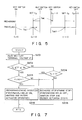
- the assist ratio K was found to be 0.25 to 0.5, as indicated in FIG. 4.
- the maximum required output of the generator is determined from the cost of the generator and the battery, and the space required by the generator and the battery, and the minimum required output is determined from the relationship between the minimum traveling distance and the battery capacity, and the like.
- the traveling performance of the electric automobile 1 can be determined by selecting the battery 5 and the engine 2 that are suitable as far as the cost and the weight are concerned, while at the same time producing a favorable driving sensation.
- the traveling time judgment section 35 if the traveling time T of the electric automobile 1 is judged by the traveling time judgment section 33 to not have reached the set traveling time TSET, then the count value C2 of the recharge time counter section 34 is read from the backup RAM 24 and a judgment made for whether the count value C2 is zero or not, that is, for whether the recharge time TBC of the battery 5 has finished or not.
- the recharge judgment flag FLAG stored in the backup RAM 24 is set to 1 (FLAG ⁇ 1) in the recharge judgment section 36.
- the recharge judgment flag FLAG stored in the backup RAM 24 of the storage section 32 is cleared to zero (FLAG ⁇ 0).
- the countdown values with respect to the count value C1 of the traveling time counter section 31 and the count setting value C2 of the recharge time counter section 34 are successively stored in the backup RAM 24 and are held even when the key switch 28 is off.
- the time according to the traveling time counter section 31 and the recharge time counter 34 is begun from the status when the key switch 28 was turned off.
- FLAG 0, that is, when the recharge time TBC of the battery 5 has elapsed, operation stop signals are output to the ignition drive section 38, the first and the second relay drive section 39, and the rotary actuator operation amount setting section 41.
- the generator rotation calculation section 40 the output signals of the generator rotation speed sensor 12 are read, and the rotation speed NGE of the generator is calculated from the output interval.
- amount of operation of the rotary actuator 10 is set so as to correspond to the deviation amount ⁇ between the generator rotation speed NGE calculated by the generator rotation calculation section 40 and the predetermined objective generator rotational speed Ni (such as 3,000 rpm, for example), and output to the rotary actuator drive section 42.
- the rotary actuator 10 is driven, and degree of opening of the throttle valve of the engine 2 is adjusted so that the generator rotational speed NGE of the generator 4 becomes the objective generator rotational speed Ni. Accordingly, the influence of the slip of the belt 3 is eliminated and the rotational speed of the generator 4 is accurately controlled, so that it is possible to accurately control the recharging of the battery 5.
- the operation signals from the recharge identification section 37 cause the fixed point ignition angle signals from the recharge identification section 37 to be used as the basis for the predetermined on and off timing of the primary coil of the ignition coil 16 and to spark the spark plug 17. Then, the operation stop signals from the recharge identification section 37 stop the operation and the primary coil of the ignition coil 16 is held in the nonconductive status and the engine 2 is stopped.
- the operation signals from the recharge identification section 37 turn on the first relay RY1 and the second relay RY2 of the control circuit 4b of the generator 4 and operate the generator 4 as a starter.
- the operation stop signals from the recharge identification section 37 turn off the first relay RY1 and the second relay RY2 and interrupt the connection between the generator 4 and the battery 5 so that the recharging is finished.
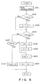
- FIG. 6 is a flow chart indicating the recharge judgment procedure, which is an interrupt program that is executed for each predetermined time when the key switch 28 is turned on.
- a step S101 the vehicle speed V is read from the speed sensor 13, and then, in a step S102, the vehicle speed V that was read in the step S101 is compared with a predetermined reference speed V0 (such as 5 km/h).
- a predetermined reference speed V0 such as 5 km/h.
- step S102 when in V ⁇ V0, the electric automobile 1 is judged to be in the standing and the sprogram jumps to a step S104, and if V ⁇ V0, it is judged that the vehicle is in the traveling status and the program proceeds to a step S103.
- step S103 the count value C1 of the traveling time counter section 31 is counted up (C1 ⁇ C1 + 1). Then, the program proceeds to the step S104 where the count value C1 of the traveling time counter section 31 and the count setting value CSET are compared.
- C1 ⁇ CSET it is judged that the traveling time T of the electric automobile 1 has reached the predetermined set traveling time TSET (such as 1 hour, for example) and the program proceeds to a step S105.
- the count setting value C2 corresponding to the recharge time TBC of the battery 5 is read from the predetermined address of the ROM 22 and set in the recharge time counter section 34.
- step S106 the count value C1 of the traveling time counter section 31 is cleared (C1 ⁇ 0) and the execution proceeds to a step S108.
- step S104 when C1 ⁇ CSET, it is judged that the traveling time T of the electric automobile 1 has not reached the set traveling time TSET, the program jumps from the step S104 to a step S107.
- the count value of the recharge time counter section 34 is read from a predetermined address in the backup RAM 24 and a judgment is made for whether C2 is zero or not in the step S107.
- step S107 when C2 > 0, that is, if the recharge time counter section 34 is currently counting, the program proceeds from the step S107 to the step S108.
- C2 ⁇ 0 in the step S107 that is, when the time of the recharge time TBC of the battery 5 has finished, the program jumps from the step S107 to a step S110 where the recharge judgment flag FLAG stored in the backup RAM 24 is cleared (FLAG ⁇ 0) and there is an escape from the program.
- the recharge judgment flag FLAG stored in the backup RAM 24 is set to 1 (FLAG ⁇ 1) and then in a step S109, the recharge time counter section 34 is counted down from the count value C2 (C2 ⁇ C2 - 1) and there is escape from the program.
- the recharge control procedure program is the same as the program- for the recharge judgment section 36 described above, i.e., the execution at predetermined times when the key switch 28 is turned on is an interrupt program.
- a step S201 the battery terminal voltage VT is read, and in a step S202, there is a judgment for whether the battery voltage VT is within the range set beforehand by the lower limit voltage VL (such as 11 V, for example) and the upper limit voltage VH (such as 15 V, for example).
- the program proceeds to a step S203, if VL ⁇ VT ⁇ VH, where the recharge judgment flag FLAG is read from a predetermined address in the backup RAM 24 and a judgment is made as to whether the battery 5 is recharged or not.
- the program proceeds from the step S203 to a step S205.
- the first relay RY1 and the second relay RY2 of the generator control circuit 4b are turned on, and the ignition signals are output to the igniter 2b.
- the rotary actuator 10 is driven to control the rotational speed of the generator 4 so that it becomes a predetermined rotational speed and there is an escape from the program.
- the signals to the generator control circuit 4b and the igniter 2b cause the generator 4 to operate as a starter, so that recharge operation by the engine 2 is begun.
- step S206 the fist relay RY1 and the second relay RY2 of the generator control circuit 4b are turned off, the ignition signals to the igniter 2b are cut and further the drive of the rotary actuator 10 is stopped to make the throttle valve 7a be placed in the fully open status so as to stop the engine 2. Then, there is an escape from the program.
- step S202 when it is judged that VL > VT, or that VH ⁇ VT, the program proceeds to a step S204.
- the battery terminal voltage VT that was read in the step S201 is compared with the lower limit value VL.
- VL > VT that is, when the battery voltage has dropped due to discharge of the battery 5
- the program proceeds from the step S204 to a step S205.
- the engine 2 is operated to recharge the battery 5 irrespective of the recharge judgment flag FLAG and there is an escape from the program.
- step S204 when VL ⁇ VT in the step S204, that is, when it is judged that VH ⁇ VT, the program proceeds to a step S206.
- the engine 2 is stopped to finish the recharging of the battery 5 in order to prevent the occurrence of gassing, the generation of noise and the waste of fuel due to overcharging of the battery 5 and there is an escape from the program.
- the present invention is not limited to the embodiment described above, as the electric automobile 1 can also be driven by a combination of the electric motor 6 and the engine 2.
- the recharge time TBC of the battery 5 can be calculated so that there is predetermined coefficient K with respect to the traveling time T of the electric automobile 1.
- the traveling set time TSET can be in accordance with the terminal voltage of the battery 5.
- the assist device 20 needs not be dependent upon a microcomputer, but can be alternatively configured from a hard logic circuit, and the time of the recharge time TBC of the battery 5 and the traveling time of the electric automobile 1 can be either counted down or counted up.
- the assist device that recharges the battery for the recharge time that is the predetermined ratio with respect to the traveling time of the vehicle that has the battery as of the driving power source. Therefore, it is possible to have suitable recharging for the battery with respect to the traveling performance of the electric automobile. In this case, it is desirable that the predetermined ratio set between 25% and 50%, and therefore achieve an optimum balance between the cost, weight and traveling performance of the electric automobile.
Landscapes
- Engineering & Computer Science (AREA)
- Transportation (AREA)
- Mechanical Engineering (AREA)
- Chemical & Material Sciences (AREA)
- Combustion & Propulsion (AREA)
- Life Sciences & Earth Sciences (AREA)
- Sustainable Development (AREA)
- Sustainable Energy (AREA)
- Power Engineering (AREA)
- Control Of Vehicle Engines Or Engines For Specific Uses (AREA)
- Electric Propulsion And Braking For Vehicles (AREA)
- Hybrid Electric Vehicles (AREA)
Applications Claiming Priority (2)
| Application Number | Priority Date | Filing Date | Title |
|---|---|---|---|
| JP305009/89 | 1989-11-22 | ||
| JP1305009A JP2893603B2 (ja) | 1989-11-22 | 1989-11-22 | 電気自動車 |
Publications (3)
| Publication Number | Publication Date |
|---|---|
| EP0429058A2 true EP0429058A2 (de) | 1991-05-29 |
| EP0429058A3 EP0429058A3 (en) | 1991-09-18 |
| EP0429058B1 EP0429058B1 (de) | 1993-09-08 |
Family
ID=17939988
Family Applications (1)
| Application Number | Title | Priority Date | Filing Date |
|---|---|---|---|
| EP90122175A Expired - Lifetime EP0429058B1 (de) | 1989-11-22 | 1990-11-20 | Elektrisches Fahrzeug |
Country Status (4)
| Country | Link |
|---|---|
| US (1) | US5150045A (de) |
| EP (1) | EP0429058B1 (de) |
| JP (1) | JP2893603B2 (de) |
| DE (1) | DE69003225T2 (de) |
Cited By (4)
| Publication number | Priority date | Publication date | Assignee | Title |
|---|---|---|---|---|
| EP0887222A1 (de) * | 1997-06-24 | 1998-12-30 | Electrolux Euroclean Italia S.p.A. | Verbesserungen im Motorantriebssystem eines selbstfahrenden Fahrzeuges |
| US6349545B1 (en) | 1999-04-26 | 2002-02-26 | Nilfisk-Advance Italia S.P.A. | Hybrid propulsion system and self-propelled vehicle propelled by this system |
| EP1283122A3 (de) * | 2001-08-10 | 2003-12-17 | Aisin Aw Co., Ltd. | Antriebsregelvorrichtung und Verfahren für ein Fahrzeug des Typs Hybrid und zugehöriges Programm |
| EP1522447A3 (de) * | 2003-10-08 | 2007-01-03 | Nissan Motor Company, Limited | Fahrzeugantrieb mit Generatorsteuerung |
Families Citing this family (12)
| Publication number | Priority date | Publication date | Assignee | Title |
|---|---|---|---|---|
| JPH04347536A (ja) * | 1991-05-22 | 1992-12-02 | Honda Motor Co Ltd | 車両用電気的負荷制限装置 |
| JPH05270294A (ja) * | 1992-03-23 | 1993-10-19 | Mitsubishi Motors Corp | 内燃機関を有する電気自動車の制御装置 |
| EP0817352A2 (de) * | 1992-08-18 | 1998-01-07 | Black & Decker Inc. | Verbesserungen in Batteriegetriebenen elektrischen Maschinen |
| US5487002A (en) * | 1992-12-31 | 1996-01-23 | Amerigon, Inc. | Energy management system for vehicles having limited energy storage |
| US6018200A (en) * | 1994-09-14 | 2000-01-25 | Coleman Powermate, Inc. | Load demand throttle control for portable generator and other applications |
| US6118186A (en) * | 1994-09-14 | 2000-09-12 | Coleman Powermate, Inc. | Throttle control for small engines and other applications |
| US5764025A (en) * | 1996-09-16 | 1998-06-09 | Lehmann; Robert J. | Vehicle battery |
| EP1237256A3 (de) * | 2001-02-28 | 2004-11-10 | Hitachi, Ltd. | Getriebe für Fahrzeugwechselstromgenerator |
| DE10331084A1 (de) | 2003-07-09 | 2005-03-24 | Aloys Wobben | Kraftfahrzeug |
| JP4890953B2 (ja) | 2006-06-13 | 2012-03-07 | オリンパス株式会社 | カプセル内視鏡システム |
| JP4718526B2 (ja) * | 2007-08-08 | 2011-07-06 | 本田技研工業株式会社 | 燃料電池車両 |
| US8403086B1 (en) * | 2007-10-05 | 2013-03-26 | Leonard Michael Free | System, method and apparatus for supplying supplemental power to an electric vehicle |
Family Cites Families (6)
| Publication number | Priority date | Publication date | Assignee | Title |
|---|---|---|---|---|
| JPS4930648B1 (de) * | 1969-12-12 | 1974-08-15 | ||
| US3792327A (en) * | 1972-10-05 | 1974-02-12 | L Waldorf | Hybrid electrical vehicle drive |
| US4218644A (en) * | 1978-09-19 | 1980-08-19 | Gould Inc. | Time controlled battery charger |
| DE2945303A1 (de) * | 1979-11-09 | 1981-05-21 | Volkswagenwerk Ag | Hybridantrieb fuer ein fahrzeug |
| DE3112629A1 (de) * | 1981-03-30 | 1982-10-07 | Volkswagenwerk Ag, 3180 Wolfsburg | "verfahren zum betrieb eines hybridfahrzeuges" |
| DE3142038A1 (de) * | 1981-10-23 | 1983-05-05 | GES Gesellschaft für elektrischen Straßenverkehr mbH, 4300 Essen | Verfahren und anordnung zur ermittlung einer restlichen fahrreichweite bei einem elektrofahrzeug |
-
1989
- 1989-11-22 JP JP1305009A patent/JP2893603B2/ja not_active Expired - Lifetime
-
1990
- 1990-11-19 US US07/615,242 patent/US5150045A/en not_active Expired - Fee Related
- 1990-11-20 DE DE90122175T patent/DE69003225T2/de not_active Expired - Fee Related
- 1990-11-20 EP EP90122175A patent/EP0429058B1/de not_active Expired - Lifetime
Cited By (5)
| Publication number | Priority date | Publication date | Assignee | Title |
|---|---|---|---|---|
| EP0887222A1 (de) * | 1997-06-24 | 1998-12-30 | Electrolux Euroclean Italia S.p.A. | Verbesserungen im Motorantriebssystem eines selbstfahrenden Fahrzeuges |
| US6349545B1 (en) | 1999-04-26 | 2002-02-26 | Nilfisk-Advance Italia S.P.A. | Hybrid propulsion system and self-propelled vehicle propelled by this system |
| EP1283122A3 (de) * | 2001-08-10 | 2003-12-17 | Aisin Aw Co., Ltd. | Antriebsregelvorrichtung und Verfahren für ein Fahrzeug des Typs Hybrid und zugehöriges Programm |
| US6902018B2 (en) | 2001-08-10 | 2005-06-07 | Aisin Aw | Electric vehicle drive control apparatus, electric vehicle drive control method, and program thereof |
| EP1522447A3 (de) * | 2003-10-08 | 2007-01-03 | Nissan Motor Company, Limited | Fahrzeugantrieb mit Generatorsteuerung |
Also Published As
| Publication number | Publication date |
|---|---|
| EP0429058A3 (en) | 1991-09-18 |
| DE69003225T2 (de) | 1994-04-21 |
| EP0429058B1 (de) | 1993-09-08 |
| JPH03169204A (ja) | 1991-07-22 |
| DE69003225D1 (de) | 1993-10-14 |
| JP2893603B2 (ja) | 1999-05-24 |
| US5150045A (en) | 1992-09-22 |
Similar Documents
| Publication | Publication Date | Title |
|---|---|---|
| EP0429058B1 (de) | Elektrisches Fahrzeug | |
| US5664635A (en) | Control system for inhibiting unintended use of hybrid electric vehicle | |
| US5115183A (en) | Battery charging system for motor-generator | |
| KR0136743B1 (ko) | 하이브리드 차의 운전방법 | |
| EP0570234B1 (de) | Verfahren zum Betrieb eines hybriden Fahrzeugs | |
| EP1095809B1 (de) | Hilfsantriebssteuerungssystem eines Hybridfahrzeugs | |
| US7906864B2 (en) | Apparatus and method of controlling generation of electric power in vehicle | |
| US5969624A (en) | Battery charge control system for a hybrid vehicle driven by an electric motor and an internal combustion engine | |
| US6469403B2 (en) | Control apparatus for hybrid vehicle | |
| EP1036696A1 (de) | System zur Regelung des Verbrennungsmotors in einem Hybridauto | |
| EP0424906B1 (de) | Automatisches Ladesystem für elektrische Fahrzeuge | |
| JP2004248405A (ja) | 車両のバッテリ管理装置 | |
| JP2000013910A (ja) | ハイブリッド駆動車両の制御装置 | |
| JP2874448B2 (ja) | ハイブリッド車の発電用内燃エンジンの運転方法 | |
| JP3682686B2 (ja) | モータ駆動制御のバッテリ管理装置 | |
| JP2583834B2 (ja) | 車載発電機制御装置 | |
| JPH10304512A (ja) | ハイブリッド車 | |
| JP2929475B2 (ja) | ハイブリッド車のバッテリ充電制御装置 | |
| KR100290365B1 (ko) | 하이브리드 전기 자동차의 엔진 회전수 제어 장치 및 그 방법 | |
| JPH03155306A (ja) | バッテリ充電装置 | |
| JP2024172879A (ja) | 車両の制御装置 | |
| JPH05328527A (ja) | ハイブリッド車の発電用内燃エンジンの運転方法 | |
| JP7566424B2 (ja) | ハイブリッド車両の制御装置 | |
| JP7191476B2 (ja) | 車両の制御システム | |
| JP2004248406A (ja) | 車両のバッテリ管理装置 |
Legal Events
| Date | Code | Title | Description |
|---|---|---|---|
| PUAI | Public reference made under article 153(3) epc to a published international application that has entered the european phase |
Free format text: ORIGINAL CODE: 0009012 |
|
| 17P | Request for examination filed |
Effective date: 19901120 |
|
| AK | Designated contracting states |
Kind code of ref document: A2 Designated state(s): DE FR GB |
|
| PUAL | Search report despatched |
Free format text: ORIGINAL CODE: 0009013 |
|
| AK | Designated contracting states |
Kind code of ref document: A3 Designated state(s): DE FR GB |
|
| 17Q | First examination report despatched |
Effective date: 19921222 |
|
| GRAA | (expected) grant |
Free format text: ORIGINAL CODE: 0009210 |
|
| AK | Designated contracting states |
Kind code of ref document: B1 Designated state(s): DE FR GB |
|
| REF | Corresponds to: |
Ref document number: 69003225 Country of ref document: DE Date of ref document: 19931014 |
|
| ET | Fr: translation filed | ||
| PLBE | No opposition filed within time limit |
Free format text: ORIGINAL CODE: 0009261 |
|
| STAA | Information on the status of an ep patent application or granted ep patent |
Free format text: STATUS: NO OPPOSITION FILED WITHIN TIME LIMIT |
|
| 26N | No opposition filed | ||
| REG | Reference to a national code |
Ref country code: GB Ref legal event code: 746 Effective date: 19980924 |
|
| REG | Reference to a national code |
Ref country code: FR Ref legal event code: D6 |
|
| REG | Reference to a national code |
Ref country code: GB Ref legal event code: IF02 |
|
| PGFP | Annual fee paid to national office [announced via postgrant information from national office to epo] |
Ref country code: FR Payment date: 20021108 Year of fee payment: 13 |
|
| PGFP | Annual fee paid to national office [announced via postgrant information from national office to epo] |
Ref country code: GB Payment date: 20021120 Year of fee payment: 13 |
|
| PGFP | Annual fee paid to national office [announced via postgrant information from national office to epo] |
Ref country code: DE Payment date: 20021121 Year of fee payment: 13 |
|
| PG25 | Lapsed in a contracting state [announced via postgrant information from national office to epo] |
Ref country code: GB Free format text: LAPSE BECAUSE OF NON-PAYMENT OF DUE FEES Effective date: 20031120 |
|
| PG25 | Lapsed in a contracting state [announced via postgrant information from national office to epo] |
Ref country code: DE Free format text: LAPSE BECAUSE OF NON-PAYMENT OF DUE FEES Effective date: 20040602 |
|
| GBPC | Gb: european patent ceased through non-payment of renewal fee |
Effective date: 20031120 |
|
| PG25 | Lapsed in a contracting state [announced via postgrant information from national office to epo] |
Ref country code: FR Free format text: LAPSE BECAUSE OF NON-PAYMENT OF DUE FEES Effective date: 20040730 |
|
| REG | Reference to a national code |
Ref country code: FR Ref legal event code: ST |