EP0434889A2 - Wechselrichter und Leistungsversorgungseinrichtung desselben - Google Patents
Wechselrichter und Leistungsversorgungseinrichtung desselben Download PDFInfo
- Publication number
- EP0434889A2 EP0434889A2 EP90107105A EP90107105A EP0434889A2 EP 0434889 A2 EP0434889 A2 EP 0434889A2 EP 90107105 A EP90107105 A EP 90107105A EP 90107105 A EP90107105 A EP 90107105A EP 0434889 A2 EP0434889 A2 EP 0434889A2
- Authority
- EP
- European Patent Office
- Prior art keywords
- switch
- circuit
- transformer
- interval
- voltage
- Prior art date
- Legal status (The legal status is an assumption and is not a legal conclusion. Google has not performed a legal analysis and makes no representation as to the accuracy of the status listed.)
- Granted
Links
Images




Classifications
-
- H—ELECTRICITY
- H02—GENERATION; CONVERSION OR DISTRIBUTION OF ELECTRIC POWER
- H02M—APPARATUS FOR CONVERSION BETWEEN AC AND AC, BETWEEN AC AND DC, OR BETWEEN DC AND DC, AND FOR USE WITH MAINS OR SIMILAR POWER SUPPLY SYSTEMS; CONVERSION OF DC OR AC INPUT POWER INTO SURGE OUTPUT POWER; CONTROL OR REGULATION THEREOF
- H02M3/00—Conversion of DC power input into DC power output
- H02M3/22—Conversion of DC power input into DC power output with intermediate conversion into AC
- H02M3/24—Conversion of DC power input into DC power output with intermediate conversion into AC by static converters
- H02M3/28—Conversion of DC power input into DC power output with intermediate conversion into AC by static converters using discharge tubes with control electrode or semiconductor devices with control electrode to produce the intermediate AC
- H02M3/325—Conversion of DC power input into DC power output with intermediate conversion into AC by static converters using discharge tubes with control electrode or semiconductor devices with control electrode to produce the intermediate AC using devices of a triode or a transistor type requiring continuous application of a control signal
- H02M3/335—Conversion of DC power input into DC power output with intermediate conversion into AC by static converters using discharge tubes with control electrode or semiconductor devices with control electrode to produce the intermediate AC using devices of a triode or a transistor type requiring continuous application of a control signal using semiconductor devices only
- H02M3/33569—Conversion of DC power input into DC power output with intermediate conversion into AC by static converters using discharge tubes with control electrode or semiconductor devices with control electrode to produce the intermediate AC using devices of a triode or a transistor type requiring continuous application of a control signal using semiconductor devices only having several active switching elements
- H02M3/33576—Conversion of DC power input into DC power output with intermediate conversion into AC by static converters using discharge tubes with control electrode or semiconductor devices with control electrode to produce the intermediate AC using devices of a triode or a transistor type requiring continuous application of a control signal using semiconductor devices only having several active switching elements having at least one active switching element at the secondary side of an isolation transformer
- H02M3/33584—Bidirectional converters
-
- H—ELECTRICITY
- H02—GENERATION; CONVERSION OR DISTRIBUTION OF ELECTRIC POWER
- H02M—APPARATUS FOR CONVERSION BETWEEN AC AND AC, BETWEEN AC AND DC, OR BETWEEN DC AND DC, AND FOR USE WITH MAINS OR SIMILAR POWER SUPPLY SYSTEMS; CONVERSION OF DC OR AC INPUT POWER INTO SURGE OUTPUT POWER; CONTROL OR REGULATION THEREOF
- H02M1/00—Details of apparatus for conversion
- H02M1/0003—Details of control, feedback or regulation circuits
- H02M1/0032—Control circuits allowing low power mode operation, e.g. in standby mode
-
- Y—GENERAL TAGGING OF NEW TECHNOLOGICAL DEVELOPMENTS; GENERAL TAGGING OF CROSS-SECTIONAL TECHNOLOGIES SPANNING OVER SEVERAL SECTIONS OF THE IPC; TECHNICAL SUBJECTS COVERED BY FORMER USPC CROSS-REFERENCE ART COLLECTIONS [XRACs] AND DIGESTS
- Y02—TECHNOLOGIES OR APPLICATIONS FOR MITIGATION OR ADAPTATION AGAINST CLIMATE CHANGE
- Y02B—CLIMATE CHANGE MITIGATION TECHNOLOGIES RELATED TO BUILDINGS, e.g. HOUSING, HOUSE APPLIANCES OR RELATED END-USER APPLICATIONS
- Y02B70/00—Technologies for an efficient end-user side electric power management and consumption
- Y02B70/10—Technologies improving the efficiency by using switched-mode power supplies [SMPS], i.e. efficient power electronics conversion e.g. power factor correction or reduction of losses in power supplies or efficient standby modes
Definitions
- the present invention relates to an inverter for supplying electrical energy from a DC supply to a load.
- the invention may also be advantageously used in uninterrupted power supplies and standby power supplies, and is therefore described below also with respect to these applications.
- inverter circuits are known for converting DC to AC.
- One known circuit called the "flyback" type, and described for example in the article "A New Family of Single-Phase and Three-Phase Inverters” by Sayed-Amr El-Hamamsy and R.D. Middlebrook, PCI, October 1985 Proceedings, Pages 84-98, includes a transformer having a primary winding coupled to the DC supply and a switch for interrupting the DC supply, causing energy to be stored in the transformer, which energy is outputted from the secondary winding.
- An object of the present invention is to provide an inverter of the "flyback" type but having a number of advantages, as will be described more particularly below.
- an inverter for supplying electrical energy from a DC supply to a load, comprising: a transformer including a primary winding circuit coupled to the DC supply, and a secondary winding circuit coupled to the load; said primary winding circuit including a first switch for interrupting the DC supply causing energy to be stored in the transformer; said secondary winding circuit including at least a second, unidirectional switch to produce an output of one sign when closed; said primary winding circuit further including an electrical device effective to return energy to the DC supply when said first and second switches are open; and a control circuit for controlling the operation of said first and second switches.
- the secondary winding circuit includes a third, unidirectional switch poled in the opposite direction as the second switch, such as to produce, when it is the active switch in the secondary winding circuit instead of the second switch, and is closed, an output of the opposite sign as said second switch.
- the control circuit includes: means for closing the first switch and opening the second or third switch to start a first Interval in each cycle during which energy is stored in the transformer; means operative at the end of the first Interval to open the first switch and to close the active second or third switch to start a second Interval in each cycle during which energy stored in the transformer is delivered to the load or, in the case of a reactive load, energy in the load is stored in the transformer; and means operative at the end of the second Interval to open all the switches to start a third Interval during which excess energy then stored in the transformer may be returned to the DC supply via the primary winding circuit.
- such an inverter is capable of four-quadrant operation, wherein energy is supplied to the load during the first and third quadrants, and excess energy stored in the transformer or in the load may be returned to the DC supply for recharging it during the second and fourth quadrants.
- the inverter of the present invention also permits fast and stable control.
- the four-quadrant operation of the inverter provides particular advantages when used in an uninterrupted power supply and also in a standby power supply. Thus, it obviates the need for the provision of large separate chargers normally required in such systems in order to keep the back-up power supply fully charged. The invention is therefore described below also with respect to these applications.
- the primary winding control subcircuit opens the first switch at the beginning of each cycle and closes the first switch at a subsequent point in the cycle when, at the end of the respective cycle, the energy stored in the transformer would reach a predetermined value; and the secondary winding control subcircuit closes the second switch at the beginning of the respective cycle and opens the second switch when the voltage at the output of the secondary winding circuit reaches a predetermined value; such that a first interval is started by the opening of the first switch and closing of the second switch, during which energy in the transformer is delivered to the load; a second interval is started by the opening of the second switch during which excess energy in the transformer is returned to the power supply; and a third interval is started by the closing of the first switch during which energy is stored in the transformer.
- Interval II in the latter embodiment starts by the opening of the secondary winding switch (the “second swtich"), when the voltage at the output of the secondary winding circuit reaches a predetermined value, and ends by the closing of the primary winding switch (the “first switch") at the point in the cycle when, at the end of the cycle, the energy stored in the transformer would reach a predetermined value.
- Such a "floating" arrangement for determining the interval during which excess energy stored in the transformer is delivered to the power supply produces a more efficient and stable operation.
- Fig. 1 is a block diagram illustrating the main components of an inverter constructed in accordance with the present invention, and Fig. 2 more particularly illustrates those components.
- the inverter comprises a DC battery supply 2, feeding power to a transformer 4 via a primary winding switching circuit 6.
- the secondary winding of transformer 4 is controlled by a secondary winding switching circuit 8 so as to output the power to a load 10 via an output filter 12.
- a control unit 14 receives inputs from the input to the primary winding circuit of the transformer 4, and also from the output of the transformer secondary winding circuit to the load 10, and controls the primary winding switching circuit 6 and the secondary winding switching circuit 8 in response to such inputs.
- Fig. 2 more particularly illustrates the main components of the inverter of Fig. 1.
- transformer 4 includes two primary windings N1, N2 connected to the DC supply 2, and two secondary windings N3, N4 for supplying power to the load 10 via filter 12, and also via an output capacitor 16 connected to the output circuit of the transformer secondary windings.
- the load 10 may be a reactive load, so that it receives energy from the inverter during the first and third quadrants, and gives energy back to the inverter during the second and fourth quadrants.
- the primary winding switching circuit shown by block 6 in Fig. 1 includes a switch S1 between the DC supply and primary winding N2, which switch is interrupted under the control of the control unit 14 for causing energy to be stored in the transformer.
- the primary winding switching circuit further includes a unidirectional conducting device or diode D1, in series with the power supply and primary winding N1. Diode D1 is effective to deliver energy back to the DC supply 2 during the second and fourth-quadrants as will be described more particularly below.
- the secondary switching circuit indicated by block 8 in Fig. 2 includes two further switches S2, S3 poled in opposite directions by their respective unidirectional conducting devices D2, D3.
- One of these two switches would be active during each cycle of operation, depending on the sign of the output supplied by the inverter to the load.
- switch S3 is the active one
- switch S2 would be continuously open, and switch S3 would be closed during precise Intervals of each cycle to output pulses on one sign; whereas if switch S2 is the active one, switch S3 would be continuously open and switch S2 would be closed at precise Intervals to output pulses of the opposite sign.
- Switches S1, S2, S3 are controlled by control unit 14 in such a manner as to achieve four-quadrant operation with fast control.
- the four-quadrant operation is permitted by the addition of the above-mentioned diode D1 in the primary winding circuit, such that diode D1 provides a path for charging the battery supply 2 at a certain Interval during each cycle in which the energy, stored in the transformer and not used in the load, is returned to the battery supply for charging it.
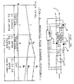
- Interval II is normally an energy-delivering Interval and is started by the opeing of switch S1 and the closing of the active switch S2 or S3, depending on the sign of the output current.
- the energy stored in the transformer is used for charging the capacitor 16 (Fig. 2) for delivery to the load (10, Fig. 1) via the secondary winding N3 or N4, depending on whether switch S2 or S3 is the active one and is closed.
- I s I os -(V out .t)/L s
- I s is the instantaneous current in the secondary winding
- I os is I op (N p /N s ).
- Interval III starts by closing the active switch S2 or S3, whichever one had been closed in Interval II according to the sign of the output, switch S1 in the primary winding circuit remaining open. Accordingly, all the switches are open.
- I d I od -(V dc .t)/L p
- I d is the instantaneous current through diode D1 and winding N1 to the battery supply 2
- I od is the starting current through winding N1
- L p is the inductance of the primary winding N1.
- descending line IIIa in Fig. 3 thus describes the excess energy returned to the power supply, via the diode D1 and primary winding N1, during Quadrants 2 and 4, whereas descending line IIIc describes the excess energy returned to the power supply during Quadrants 2 and 4 in a reactive load.
- Fig. 2a illustrates an arrangement of the primary winding circuit that may be used for effecting the operation illustrated by the horizontal line IIIb in Fig. 3.
- the primary winding circuit shown in Fig. 2a also includes primary winding N1 containing diode D1 and primary winding N2 containing switch S1, as in Fig. 2. However, it includes an additional switch S4 which is closed at the beginning of Interval III (Fig. 3) in order to short circuit winding N1, and thereby to preserve in the transformer the excess energy not delivered to the load during Interval II.
- Fig. 4 illustrates the control circuit 14 which is used for controlling the switches S1, S2 and S3 in the primary and secondary winding circuits illustrated in Fig. 2, and also switch S4 in the modification to the primary winding circuit illustrated in Fig. 2a if that modification is used.
- Figs. 5-7 illustrate more particulars of the various components used in control circuit 14.
- control circuit 14 includes a primary winding control subcircuit 20 (more particularly illustrated in Fig. 5) which controls switch S1 in the primary winding circuit; a secondary winding control subcircuit 30 (more particularly illustrated in Fig. 6) which controls switches S2 and S3; a flux level reference generator 40 (more particularly illustrated in Fig. 7); and a reference voltage generator 50, which controls the secondary winding control subcircuit 30.
- the primary winding control subcircuit 20 is effective to sense the energy stored in the transformer and to open switch S1 when the stored energy reaches a predetermined value as fixed by the flux level reference generator 40; and the secondary winding control subcircuit 30 is effective to sense the output voltage in the secondary winding circuit of the transformer and to open the active switch S2 or S3 (depending on the polarity of the output) when the output voltage reaches a predetermined value as fixed by the reference voltage generator 50.
- Fig. 5 more particularly illustrates the primary winding control subcircuit 20. It includes a current sensor 21 for sensing the current through switch S1 in the primary winding circuit, and a comparator 22 which receives the latter sensed current. Comparator 22 also receives a signal from the flux level reference generator 40 which, as described above, fixes the predetermined value to be reached by the stored energy when switch S1 is to be opened to end the energy-storing Interval I and to start the energy-delivering Interval II. Comparator 22 compares the sensed current from sensor 21, and the predetermined value fixed by the flux level reference generator 40, and actuates a flip-flop 23 to open switch S1 when the two values are equal. Thus, flip-flop 23 is set at the start of each cycle when switch S1 is closed, and is reset by the output from comparator 22, when the two values sensed by the comparator are equal, to open switch S1.
- Fig. 6 illustrates the secondary winding control subcircuit represented by box 30 and also by the reference voltage generator 50 in Fig. 4.
- this secondary winding controlled subcircuit senses the output voltage in the secondary winding circuit of the transformer, and when the output voltage reaches a predetermined value as fixed by the reference voltage generator 50, opens the active secondary-winding, switch S2, S3 (depending on the polarity of the output voltage), to thereby end the energy-delivering Interval II and to start Interval III during the which the excess energy is delivered back to the DC supply via diode D1 and primary winding N1 (Fig. 2).
- the secondary winding control subcircuit illustrated in Fig. 6 includes a comparator 31 connected to a summing amplifier 32 which receives a first input A from the reference voltage generator 50, and a second input B from the output side 33 of the active secondary-winding switch, S2 or S3, so as to sense the output voltage of the inverter.
- summing amplifier 32 connected to comparator 31 includes two further inputs, namely: a third input C from a correction offset signal generator 34, which senses the output current and generates a correction offset signal proportional thereto; and a fourth input D from a bidirectional sawtooth generator 35, which generates a signal whose magnitude and sign are a function of the output current. Accordingly, the summing amplifier 32 will produce, from all the foregoing inputs, an output signal ( ⁇ A+ ⁇ B + ⁇ C+ ⁇ D), which signal is applied to comparator 31.
- Comparator 31 thus produces an output signal when the output voltage from the inverter reaches the predetermined value fixed by the reference voltage generator 50.
- This output signal is applied to a flip-flop 36, which is set at the beginning of the energy-delivering Interval II, and reset by the output from the comparator 31 at the end of the energy-delivering Interval II. Ending of Interval II starts the recharging Interval III during which the DC power supply 2 is recharged by the excess energy stored in the transformer during Interval I and not delivered to the load during Interval II.
- the secondary winding control subcircuit 30 illustrated in Fig. 6 further includes an EXCLUSIVE-OR circuit 37 which operates as a gate to invert (or not invert) the comparator signal according to the quadrant of the output voltage. That is, if the output voltage is negative, it is inverted; and if positive, it is not inverted. Circuit 37 could be omitted if the values inputted into comparator 31, via its summing amplifier 32, are absolute values.
- Interval III is actually the remainder of the cycle, after the completion of the energy-storing Interval I and the energy-delivering Interval II, during which all of the switches S1, S2 or S3 are open.
- the flux reference generating circuit 40 which controls the primary winding control subcircuit 20 (Fig. 4), is used for this purpose.
- the flux level reference generator 40 includes a sensor 41 for sensing the absolute value of the output voltage, which is applied as a first input A into a differential amplifier 42 functioning as a subtractor circuit.
- Differential amplifier 42 includes a second input B from the reference voltage generator 50, converted to an absolute value by circuit 43.
- the latter circuit subtracts input B from input A, and thereby produces an output signal representing the difference between the required output voltage and the actual output voltage.
- This signal is fed to an integrator 44 via diode 45 which increases the flux level reference signal used for controlling the instant of opening of switch S1 to terminate the energy-storing Interval I.
- this latter reference signal is decreased according to an exponential decay during Interval III during when all of the switches S1, S2 or S3 are open.
- the flux reference signal outputted from integrator 44 is coupled to its input via switch 46 which is closed during Interval III by the control circuit 14.
- Fig. 2a described above illustrates a variation that may be made in the transformer primary winding circuit when it is not necessary to use the excess energy in Interval III for recharging the power supply.
- Fig. 8a illustrates another variation that may be used in the transformer primary winding circuit; and
- Figs. 8b and 8c illustrate variations that may be made in the transformer secondary winding circuit.
- Fig. 8a illustrates the use of two diodes D 1a , D 1b and the two switches S 1a , S 1b in the transformer primary winding circuit, instead of a single diode D1 and a single switch S1.
- both switches S 1a , S 1b would be opened and closed together.
- one of the switches e.g., S 1b
- Fig. 8b illustrates a variation that may be made in the transformer secondary winding circuit, wherein, instead of using two unidirectional switches S2, D2 and S3, D3, the secondary winding circuit includes a bridge having four arms with a unidirectional switch in each of the four arms.
- two arms include the two switches S2 a , S2 b and their diodes D 2a , D 2b , corresponding to switch S2 and diode D2 in Fig. 2; and the other two arms include switches S 3b , S 3b and diodes D 3a , D 3b , corresponding to switch S3 and diode D3 in Fig. 2.
- Fig. 8c illustrates a further variation in the secondary winding circuit including two unidirectional switches, comprising S2' and D2 ⁇ in series with one secondary winding and N3 ⁇ , and switch S3' and diode D3 ⁇ in series with the other secondary winding N4 ⁇ .
- FIGs. 9 and 10 illustrate two systems which may be used for this purpose.
- the system illustrated in Fig. 9 is one wherein the input, output and battery are all voltaicly isolated from each other and from the line.
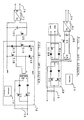
- FIG. 9 the inverter as described above, and as illustrated particularly in Fig. 2, is included within box 60, and the elements therein corresponding to those in Fig. 2 are identified by the same reference characters to facilitate understanding.
- a further switch S5 and a further coil N5 in the primary winding circuit of the transformer in the inverter and series-connected to the rectifier 62 of the power supply mains 64.
- switch S5 is controlled, instead of switch S1. That is, switch S5 is closed at the beginning of the cycle in order to start the energy- storing Interval I, and is opened to terminate that Interval and to start Interval II.
- the active secondary winding switch S2 or S3 (according to the polarity of the output voltage desired) is controlled as described above, the active switch being closed to start Interval II, and being opened to end that Interval and to start Interval III, during which the excess energy not delivered to the load may used for recharging the DC power supply.
- the battery 2 of the inverter 60 may be recharged via diode D1 in the same manner as described above with respect to Fig. 2.
- the battery supply 2 is now used for supplying the load in the same manner as described above with respect to Fig. 2.
- Fig. 10 illustrates another arrangement wherein the inverter, therein designated 70, is used in an uninterruptable power supply.
- the battery of the inverter is voltaicly coupled to the supply mains 74 via its rectifier 72, so that the battery is continuously and controllably charged by excess energy not delivered to the load and returned to the battery in Interval III as described above.
- the additional switch S5, corresponding to switch S5 in Fig. 9, is controlled in the same manner as described above with respect to switch S1; that is, it is closed at the start of each cycle and is opened at the end of the energy-storing Interval I.
- the active seconardy-winding switch S2 or S3 in the secondary winding circuit is controlled in the same manner as described above with respect to Fig. 2, the active switch being closed at the start of Interval II and being reopened at the end of that Interval and at the start of Interval III when the excess energy may be returned to the battery.
- switches S 1a and S 1b are now used for controlling the transformer primary winding circuit, being closed at the start of the energy-storing Interval I and opened at the end of that Interval and the start Interval II, in the same manner as described above with respect to Fig. 2.
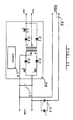
- FIG. 11 illustrates one such arrangement wherein the inverter, indicated by the elements within block 80, is substantially of the same construction and operates in substantially the same manner as described above, and is connected to the load in parallel with the power supply mains 82.
- the inverter is connected in parallel with the power supply mains by a thyristor network 84 and operates at a somewhat lower voltage than the line voltage, so that the battery is charged during the operation of the system in a continuous manner in the second and fourth quadrants.
- thyristor network 84 ceases to conduct, whereby the inverter circuit now supplies the power to the load and continues to do so until normal power is restored to the supply mains.
- the magnetic flux diagram illustrated in Fig. 12 corresponds to the diagram illustrated in Fig. 3 except that, whereas in Fig. 3 the starting and termination points of the interval (therein Interval III) during which excess energy is delivered to the power supply are fixed in the cycle, in Fig. 12 this interval (therein designated Interval II) is not fixed for each cycle, but rather "floats". This requires tha the control sequence be changed so that the cycle in the embodiment of the present application begins with conduction in the secondary winding circuit, rather than in the primary winding circuit.
- the primary winding control circuit opens switch S1 at the beginning of each cycle and closes switch S1 at a subsequent point in the cycle when, at the end of the cycle, the energy stored in the transformer would reach a predetermined value; and the secondary winding circuit control subcircuit closes switch S2 at the beginning of the cycle, and opens switch S2 when the voltage at the output of the secondary winding circuit reaches a predetermined value.
- a first interval is started by the opening of switch S1 and closing of the active secondary winding switch (S2 or S3) during which energy in the transformer is delivered to the load;
- a second interval is started by the opening of the active switch S2 or S3 during which excess energy in the transformer is returned to the power supply;
- a third interval is started by the closing of switch S1, during which energy is stored in the transformer.
- Interval II when the excess energy in the transformer is delivered to the power supply, is normally indicated by the descending line IIa or IIb, respectively. However, if the modification illustrated in Fig. 2a is used, including a switch which short circuits one of the coils, then the level of the energy in the transformer stays constant, as indicated by line IIc.
- Interval III in Fig. 12 when the energy stored in the transformer is delivered to the load, is indicated by the ascending line IIIa, IIIb or IIIc, respectively.
- Fig. 13 illustrates one form of primary winding control subcircuit, generally designated 100, that may be used for controlling switch S1 in the primary winding circuit in accordance with the sequence illustrated by the diagram of Fig. 12.
- This circuit corresponds to circuit 20 in Fig. 5 , but is designed so that it opens switch S1 at the beginning of each cycle and closes the switch at a subsequent point in the cycle when, at the end of the cycle, the energy stored in the transformer would reach a predetermined value.
- This value is predetermined during each cycle by a flux demand estimator, generally designated 102 included in the primary winding control subcircuit 100, which generates a voltage corresponding to the required flux to satisfy the load.
- the generated voltage corresponds to a reference flux depending on the load, but may also correspond to a constant reference flux.
- circuit 100 in Fig. 13 includes a "gain block" unit 104, which may be an amplifier or attenuator changing scales, connected across the input voltage, as shown by connection 106, to generate a voltage corresponding to the input voltage; and a sawtooth generator 108 also connected to the input voltage connection 106 for generating a further voltage also depending on the input voltage but varying with time.
- the three voltages produced by units 102, 104 and 108 are inputted into a summing circuit 110 which adds the outputs of the flux-demand estimator 102 and the sawtooth generator 108, and subtracts the output from the gain block circuit 104, to output a voltage which is applied to one input of a comparator 112.
- comparator 112 The other input of comparator 112 is from a magnetic flux-measuring circuit 114, which outputs a voltage corresponding to the flux in the transformer T r .
- Comparator 112 controls a flip-flop 115, which in turn controls the switch S1 in the primary winding of the transformer T r
- Flip-flop 115 is reset at the beginning of each cycle to open switch S1, and thus to end the energy-storing Interval I (line Ia or Ib, Fig. 12) during which the active switch (S2 or S3) in the secondary winding circuit is closed, so that energy stored in the transformer is delivered to the load.
- Switch S1 remains open during Interval II (line IIa, IIb, or IIc, Fig. 12) when excess energy is delivered to the power supply, but closes to end Interval II at the subsequent point in the cycle when, at the end of the cycle, the energy stored in the transformer would reach a predetermined value as determined by comparator 112, which controls flip-flop 115 to close switch S1, as described above.
- the closing of switch S1, end Interval II starts Interval III, during which energy is stored in the transformer, this interval being ended by the end of the cycle, when switch S1 is opened by the resetting of flip-flop 115.
- circuit 100 illustrated in Fig. 13 operates to close switch S1 according to the following approximation equation: wherein: FLX is the instantaneous flux in the transformer; REF-FLUX is the flux to be established at the end of the cycle; V b is the source voltage at the primary side; N p is the number of turns of the primary winding; T is the period of the cycle; and t is the instantaneous time.
- summing circuit 110 continuously adds the REF-FLUX from the flux-demand estimator 102 and the sawtooth signal from the sawtooth generator 108 (whose output is dependent on the source voltage and varies with time), and subtracts a fixed value from gain block 104, which is dependent on the source voltage; and applies this sum to one input of comparator 112.
- This sum is continuously compared with the FLUX from the flux-measurement block 114; and at the instant FLUX is smaller than the sum from the summation circuit 110, the flip-flop 115 is set to close switch S1 in the primary winding, thereby ending Interval II during which excess energy is delivered to the power supply, and starting Interval III during which energy is stored in the transformer. Switch S1 is reopened at the beginning of the next cycle by resetting of flip-flop 115.
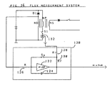
- Fig. 14 illustrates a flux-measurement system which may be used for block 114 in Fig. 13 for measuring the magnetic flux in the transformer Tr.
- This system is based on integrating the voltage measured across one of the windings of the transformer, and correcting the integration constant during the part of each cycle when switch S1 is closed, by disabling the integration of the measured voltage and replacing momentarily the integration of the voltage by a known variable related to flux.
- the voltage is measured across winding N D containing diode D1; and the known variable which is related to flux, and which is momentarily replaced in the integration, is the current flowing through winding Np.
- the integration can be based on the voltage measured across any winding of the transformer, and that the known variable which is momentarily used in the integration process for correcting the integration constant may be another known variable related to the flux, e.g., current in another winding.
- flux-measurement system illustrated in Fig. 14 includes an auxiliary winding Nd in the circuit including the diode D1, for measuring the voltage across the transformer in order to perform the integration.
- the circuit in Fig. 14 further includes an inverting integrator, generally designated 120, comprising an amplifier 122, capacitor 124, and resistor 126, for integrating the voltage across the transformer as sensed by winding Nd.
- Circuit 120 further includes resistors 128 and 130, and switch S x ; switch S x is closed together with switch S1 in the primary winding.
- the circuit illustrated in Fig. 14 further includes a current measuring circuit 132 for measuring the current in the primary winding of the transformer Tr.
- switch S x When the current starts to flow in the primary winding, switch S x is closed, and the output voltage is forced to be proportional to the real flux.
- the integration circuit 120 integrates the measured voltage with respect to time; but when the primary winding switch S1 is closed, switch S x is also closed so as to correct the integration constant, by disabling the integration of the measured voltage, and instead forcing the output to track the real current flow, i.e., the output of the current measuring circuit 132.
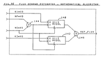
- This regulation may be implemented by two methods: one is by mathematically calculating REF-FLUX; and the other is by utilizing an energy dependent feedback system.
- Fig. 15 illustrates an energy dependent feedback system. based on a mathematical calculation. For the mathematical calculation approach, the following three cases are distinguished:
- V i is the voltage of the voltage source
- V o is the output voltage
- I o is the output current
- N p is the number of turns of the primary winding
- N s is the number of turns of the secondary winding
- REF-FLUX is the calculated reference flux
- Fig. 15 illustrates an electrical circuit for measuring the REF-FLUX according to the above mathematical expression.
- the circuit includes two multiplier/ divider circuits 140 and 142, and two summation circuits 144 and 146.
- the expression (k1I O ) is inputted into multiplier circuit 140 and is multiplied by the output from summation circuit 144; the latter circuit sums Np multiplied by V o , and N s multiplied by V i .
- the product is divided by the quantity N s times Vi in circuit 140, and the output is applied to summation circuit 146.
Landscapes
- Engineering & Computer Science (AREA)
- Power Engineering (AREA)
- Inverter Devices (AREA)
- Control Of Multiple Motors (AREA)
- Dc-Dc Converters (AREA)
- Emergency Protection Circuit Devices (AREA)
- Stand-By Power Supply Arrangements (AREA)
- Ac-Ac Conversion (AREA)
Applications Claiming Priority (2)
| Application Number | Priority Date | Filing Date | Title |
|---|---|---|---|
| IL92885A IL92885A0 (en) | 1989-03-03 | 1989-12-26 | Inverter |
| IL92885 | 1989-12-26 |
Publications (3)
| Publication Number | Publication Date |
|---|---|
| EP0434889A2 true EP0434889A2 (de) | 1991-07-03 |
| EP0434889A3 EP0434889A3 (en) | 1991-10-02 |
| EP0434889B1 EP0434889B1 (de) | 1995-07-12 |
Family
ID=11060723
Family Applications (1)
| Application Number | Title | Priority Date | Filing Date |
|---|---|---|---|
| EP90107105A Expired - Lifetime EP0434889B1 (de) | 1989-12-26 | 1990-04-12 | Wechselrichter und Leistungsversorgungseinrichtung desselben |
Country Status (5)
| Country | Link |
|---|---|
| EP (1) | EP0434889B1 (de) |
| JP (1) | JPH03215174A (de) |
| AT (1) | ATE125080T1 (de) |
| CA (1) | CA2014612C (de) |
| DE (1) | DE69020873T2 (de) |
Cited By (3)
| Publication number | Priority date | Publication date | Assignee | Title |
|---|---|---|---|---|
| DE19524005A1 (de) * | 1994-10-03 | 1996-04-11 | Mitsubishi Electric Corp | Motorbetriebsregler und bidirektionaler Isolations-Gleichspannungsumformer |
| ES2122902A1 (es) * | 1996-06-06 | 1998-12-16 | Univ Valencia | Regulador de cuatro cuadrantes para convertidor de potencia dc/dc o ac/dc. |
| CN114793073A (zh) * | 2022-06-21 | 2022-07-26 | 阳光电源股份有限公司 | 燃料电池发电系统和燃料电池发电电路及其控制方法 |
Family Cites Families (1)
| Publication number | Priority date | Publication date | Assignee | Title |
|---|---|---|---|---|
| DE2728377A1 (de) * | 1977-06-23 | 1979-01-11 | Siemens Ag | Schaltungsanordnung zur umwandlung von elektrischer energie |
-
1990
- 1990-04-12 EP EP90107105A patent/EP0434889B1/de not_active Expired - Lifetime
- 1990-04-12 DE DE69020873T patent/DE69020873T2/de not_active Expired - Fee Related
- 1990-04-12 CA CA002014612A patent/CA2014612C/en not_active Expired - Fee Related
- 1990-04-12 AT AT90107105T patent/ATE125080T1/de not_active IP Right Cessation
- 1990-10-04 JP JP2268269A patent/JPH03215174A/ja active Pending
Cited By (8)
| Publication number | Priority date | Publication date | Assignee | Title |
|---|---|---|---|---|
| DE19524005A1 (de) * | 1994-10-03 | 1996-04-11 | Mitsubishi Electric Corp | Motorbetriebsregler und bidirektionaler Isolations-Gleichspannungsumformer |
| GB2294369A (en) * | 1994-10-03 | 1996-04-24 | Mitsubishi Electric Corp | Motor controller and bidirectional dc-dc converter |
| GB2294369B (en) * | 1994-10-03 | 1999-04-28 | Mitsubishi Electric Corp | Motor operation controller and isolation type bidirectional DC voltage converter |
| DE19524005C2 (de) * | 1994-10-03 | 1999-08-26 | Mitsubishi Electric Corp | Bidirektionaler Isolations-Gleichspannungsumformer |
| US6335871B1 (en) | 1994-10-03 | 2002-01-01 | Mitsubishi Denki Kabushiki Kaisha | Motor operation controller and insulation type bidirectional DC voltage converter |
| ES2122902A1 (es) * | 1996-06-06 | 1998-12-16 | Univ Valencia | Regulador de cuatro cuadrantes para convertidor de potencia dc/dc o ac/dc. |
| CN114793073A (zh) * | 2022-06-21 | 2022-07-26 | 阳光电源股份有限公司 | 燃料电池发电系统和燃料电池发电电路及其控制方法 |
| CN114793073B (zh) * | 2022-06-21 | 2022-11-15 | 阳光电源股份有限公司 | 燃料电池发电系统和燃料电池发电电路及其控制方法 |
Also Published As
| Publication number | Publication date |
|---|---|
| DE69020873D1 (de) | 1995-08-17 |
| CA2014612A1 (en) | 1991-06-26 |
| CA2014612C (en) | 2000-06-27 |
| EP0434889B1 (de) | 1995-07-12 |
| DE69020873T2 (de) | 1996-04-04 |
| EP0434889A3 (en) | 1991-10-02 |
| JPH03215174A (ja) | 1991-09-20 |
| ATE125080T1 (de) | 1995-07-15 |
Similar Documents
| Publication | Publication Date | Title |
|---|---|---|
| US5220492A (en) | Inverter and power supply systems including same | |
| US4246529A (en) | Current integrating battery charger | |
| CA1080304A (en) | Electronic voltage regulator for three-phase generators | |
| EP0598105B1 (de) | Fehler-detektor für eine mehrzahl von batterien in einem batteriesicherungssystem | |
| US5754035A (en) | Apparatus and method for controlling flow of power in a transmission line including stable reversal of power flow | |
| US4241261A (en) | Circuit control to limit power drain of auxiliary power supply in UPS system | |
| NL8100742A (nl) | Laadinrichting. | |
| JPS58182726A (ja) | 直流電源の最適動作点自動設定方法および装置 | |
| US4245289A (en) | Power supply monitor | |
| US5485075A (en) | Reactive power compensating apparatus and method for reducing in switching loss in steady state operation thereof | |
| EP0316804B1 (de) | Blindleistungsregler | |
| EP0434889B1 (de) | Wechselrichter und Leistungsversorgungseinrichtung desselben | |
| US4020360A (en) | Inverter control system | |
| JP2847115B2 (ja) | 電圧信号の電圧制御方法 | |
| JP2995962B2 (ja) | 定電圧電源用給電回路 | |
| US5349283A (en) | Automatic voltage control circuit by using reactive power | |
| US3697856A (en) | Voltage regulating circuit | |
| JP2812345B2 (ja) | コンデンサ充電回路 | |
| JP2643572B2 (ja) | レーザ用電源装置の出力電圧制御方法 | |
| JP3177721B2 (ja) | 無停電電源装置の蓄電池残存容量測定法 | |
| SU855862A1 (ru) | Способ бесперебойного электроснабжени потребителей переменным током | |
| JPS63157672A (ja) | スイツチングレギユレ−タ | |
| JPS631825B2 (de) | ||
| JPH01170328A (ja) | 直列補償型電圧変動補償装置 | |
| JPH04289740A (ja) | 無停電電源装置とその運転方法及びバッテリ充電器 |
Legal Events
| Date | Code | Title | Description |
|---|---|---|---|
| PUAI | Public reference made under article 153(3) epc to a published international application that has entered the european phase |
Free format text: ORIGINAL CODE: 0009012 |
|
| AK | Designated contracting states |
Kind code of ref document: A2 Designated state(s): AT BE CH DE DK ES FR GB GR IT LI NL SE |
|
| PUAL | Search report despatched |
Free format text: ORIGINAL CODE: 0009013 |
|
| AK | Designated contracting states |
Kind code of ref document: A3 Designated state(s): AT BE CH DE DK ES FR GB GR IT LI NL SE |
|
| RHK1 | Main classification (correction) |
Ipc: H02M 7/797 |
|
| 17P | Request for examination filed |
Effective date: 19920401 |
|
| 17Q | First examination report despatched |
Effective date: 19930826 |
|
| GRAA | (expected) grant |
Free format text: ORIGINAL CODE: 0009210 |
|
| AK | Designated contracting states |
Kind code of ref document: B1 Designated state(s): AT BE CH DE DK ES FR GB GR IT LI NL SE |
|
| PG25 | Lapsed in a contracting state [announced via postgrant information from national office to epo] |
Ref country code: NL Free format text: LAPSE BECAUSE OF FAILURE TO SUBMIT A TRANSLATION OF THE DESCRIPTION OR TO PAY THE FEE WITHIN THE PRESCRIBED TIME-LIMIT Effective date: 19950712 Ref country code: LI Effective date: 19950712 Ref country code: GR Free format text: LAPSE BECAUSE OF FAILURE TO SUBMIT A TRANSLATION OF THE DESCRIPTION OR TO PAY THE FEE WITHIN THE PRESCRIBED TIME-LIMIT Effective date: 19950712 Ref country code: ES Free format text: THE PATENT HAS BEEN ANNULLED BY A DECISION OF A NATIONAL AUTHORITY Effective date: 19950712 Ref country code: DK Effective date: 19950712 Ref country code: CH Effective date: 19950712 Ref country code: BE Effective date: 19950712 Ref country code: AT Effective date: 19950712 |
|
| REF | Corresponds to: |
Ref document number: 125080 Country of ref document: AT Date of ref document: 19950715 Kind code of ref document: T |
|
| ET | Fr: translation filed | ||
| REF | Corresponds to: |
Ref document number: 69020873 Country of ref document: DE Date of ref document: 19950817 |
|
| ITF | It: translation for a ep patent filed | ||
| PG25 | Lapsed in a contracting state [announced via postgrant information from national office to epo] |
Ref country code: SE Effective date: 19951012 |
|
| REG | Reference to a national code |
Ref country code: CH Ref legal event code: PL |
|
| NLV1 | Nl: lapsed or annulled due to failure to fulfill the requirements of art. 29p and 29m of the patents act | ||
| PLBE | No opposition filed within time limit |
Free format text: ORIGINAL CODE: 0009261 |
|
| STAA | Information on the status of an ep patent application or granted ep patent |
Free format text: STATUS: NO OPPOSITION FILED WITHIN TIME LIMIT |
|
| 26N | No opposition filed | ||
| REG | Reference to a national code |
Ref country code: GB Ref legal event code: IF02 |
|
| PGFP | Annual fee paid to national office [announced via postgrant information from national office to epo] |
Ref country code: FR Payment date: 20020422 Year of fee payment: 13 |
|
| PGFP | Annual fee paid to national office [announced via postgrant information from national office to epo] |
Ref country code: GB Payment date: 20020424 Year of fee payment: 13 |
|
| PG25 | Lapsed in a contracting state [announced via postgrant information from national office to epo] |
Ref country code: GB Free format text: LAPSE BECAUSE OF NON-PAYMENT OF DUE FEES Effective date: 20030412 |
|
| PGFP | Annual fee paid to national office [announced via postgrant information from national office to epo] |
Ref country code: DE Payment date: 20031013 Year of fee payment: 14 |
|
| GBPC | Gb: european patent ceased through non-payment of renewal fee |
Effective date: 20030412 |
|
| PG25 | Lapsed in a contracting state [announced via postgrant information from national office to epo] |
Ref country code: FR Free format text: LAPSE BECAUSE OF NON-PAYMENT OF DUE FEES Effective date: 20031231 |
|
| REG | Reference to a national code |
Ref country code: FR Ref legal event code: ST |
|
| PG25 | Lapsed in a contracting state [announced via postgrant information from national office to epo] |
Ref country code: DE Free format text: LAPSE BECAUSE OF NON-PAYMENT OF DUE FEES Effective date: 20041103 |
|
| PG25 | Lapsed in a contracting state [announced via postgrant information from national office to epo] |
Ref country code: IT Free format text: LAPSE BECAUSE OF NON-PAYMENT OF DUE FEES;WARNING: LAPSES OF ITALIAN PATENTS WITH EFFECTIVE DATE BEFORE 2007 MAY HAVE OCCURRED AT ANY TIME BEFORE 2007. THE CORRECT EFFECTIVE DATE MAY BE DIFFERENT FROM THE ONE RECORDED. Effective date: 20050412 |