EP0435729A1 - Vorrichtung zum Stranggiessen von dünnen metallischen Produkten zwischen zwei gekühlten rotierenden Zylindern - Google Patents
Vorrichtung zum Stranggiessen von dünnen metallischen Produkten zwischen zwei gekühlten rotierenden Zylindern Download PDFInfo
- Publication number
- EP0435729A1 EP0435729A1 EP90403562A EP90403562A EP0435729A1 EP 0435729 A1 EP0435729 A1 EP 0435729A1 EP 90403562 A EP90403562 A EP 90403562A EP 90403562 A EP90403562 A EP 90403562A EP 0435729 A1 EP0435729 A1 EP 0435729A1
- Authority
- EP
- European Patent Office
- Prior art keywords
- cylinders
- consumable
- casting
- deformable material
- insert
- Prior art date
- Legal status (The legal status is an assumption and is not a legal conclusion. Google has not performed a legal analysis and makes no representation as to the accuracy of the status listed.)
- Withdrawn
Links
- 238000009749 continuous casting Methods 0.000 title abstract description 5
- 238000009434 installation Methods 0.000 title abstract description 4
- 238000005266 casting Methods 0.000 claims abstract description 16
- 208000029152 Small face Diseases 0.000 claims abstract description 13
- 239000000463 material Substances 0.000 claims abstract description 8
- 229910052751 metal Inorganic materials 0.000 claims abstract description 8
- 239000002184 metal Substances 0.000 claims abstract description 8
- 230000000149 penetrating effect Effects 0.000 claims abstract description 4
- 229910001338 liquidmetal Inorganic materials 0.000 claims description 5
- OKTJSMMVPCPJKN-UHFFFAOYSA-N Carbon Chemical compound [C] OKTJSMMVPCPJKN-UHFFFAOYSA-N 0.000 claims description 2
- 229920003043 Cellulose fiber Polymers 0.000 claims description 2
- RYGMFSIKBFXOCR-UHFFFAOYSA-N Copper Chemical compound [Cu] RYGMFSIKBFXOCR-UHFFFAOYSA-N 0.000 claims description 2
- 229910052782 aluminium Inorganic materials 0.000 claims description 2
- XAGFODPZIPBFFR-UHFFFAOYSA-N aluminium Chemical compound [Al] XAGFODPZIPBFFR-UHFFFAOYSA-N 0.000 claims description 2
- 229910052799 carbon Inorganic materials 0.000 claims description 2
- 229910052802 copper Inorganic materials 0.000 claims description 2
- 239000010949 copper Substances 0.000 claims description 2
- 238000012423 maintenance Methods 0.000 claims 1
- 238000007711 solidification Methods 0.000 abstract description 2
- 230000008023 solidification Effects 0.000 abstract description 2
- 239000012528 membrane Substances 0.000 abstract 1
- 230000007423 decrease Effects 0.000 description 5
- 238000007789 sealing Methods 0.000 description 3
- 229910000831 Steel Inorganic materials 0.000 description 2
- 230000006835 compression Effects 0.000 description 2
- 238000007906 compression Methods 0.000 description 2
- 230000008595 infiltration Effects 0.000 description 2
- 238000001764 infiltration Methods 0.000 description 2
- 239000010959 steel Substances 0.000 description 2
- 229920000049 Carbon (fiber) Polymers 0.000 description 1
- 238000010276 construction Methods 0.000 description 1
- 230000003247 decreasing effect Effects 0.000 description 1
- 230000000694 effects Effects 0.000 description 1
- 238000002955 isolation Methods 0.000 description 1
- 230000014759 maintenance of location Effects 0.000 description 1
- 230000035515 penetration Effects 0.000 description 1
- 239000011819 refractory material Substances 0.000 description 1
- 239000003566 sealing material Substances 0.000 description 1
Images
Classifications
-
- B—PERFORMING OPERATIONS; TRANSPORTING
- B22—CASTING; POWDER METALLURGY
- B22D—CASTING OF METALS; CASTING OF OTHER SUBSTANCES BY THE SAME PROCESSES OR DEVICES
- B22D45/00—Equipment for casting, not otherwise provided for
-
- B—PERFORMING OPERATIONS; TRANSPORTING
- B22—CASTING; POWDER METALLURGY
- B22D—CASTING OF METALS; CASTING OF OTHER SUBSTANCES BY THE SAME PROCESSES OR DEVICES
- B22D11/00—Continuous casting of metals, i.e. casting in indefinite lengths
- B22D11/06—Continuous casting of metals, i.e. casting in indefinite lengths into moulds with travelling walls, e.g. with rolls, plates, belts, caterpillars
- B22D11/0637—Accessories therefor
- B22D11/0648—Casting surfaces
- B22D11/0651—Casting wheels
-
- B—PERFORMING OPERATIONS; TRANSPORTING
- B22—CASTING; POWDER METALLURGY
- B22D—CASTING OF METALS; CASTING OF OTHER SUBSTANCES BY THE SAME PROCESSES OR DEVICES
- B22D11/00—Continuous casting of metals, i.e. casting in indefinite lengths
- B22D11/06—Continuous casting of metals, i.e. casting in indefinite lengths into moulds with travelling walls, e.g. with rolls, plates, belts, caterpillars
- B22D11/0637—Accessories therefor
- B22D11/0648—Casting surfaces
- B22D11/066—Side dams
Definitions
- the invention relates to the continuous casting of thin metallic products, in particular steel. It relates more particularly to so-called “casting between two cylinders" installations.
- these installations comprise two cylinders with substantially horizontal axes, parallel and coplanar, rotating around their axes in opposite directions, and the cooled lateral surfaces of which form the walls of the mold against which the cast liquid metal solidifies.
- the casting space is laterally limited by closure plates, called “small faces”, applied against the lateral faces of the cylinders.
- Their parts in contact with the liquid metal are generally made of refractory material with good insulating properties.
- the side of the small faces facing the cylinders can be entirely flat, but it can also have a projection, or "insert”, penetrating inside the inter-cylinder space, as in French patent application n ° 88.12074 in the name of the plaintiff.
- the contacts between the cylinders and the small faces are wedge-shaped, and it is the front face of the insert which laterally limits the casting space.
- the penetration depth of this insert in the inter-cylinder space can be uniform over its entire height, or decrease as one descends towards the neck at the center of the cylinders. The insert is then said to be "stripped".
- this insert is advantageous because it allows better control of the solidification of the product in the mold compared to the small faces.
- controlling the clearance between each cylinder and the protruding part of the insert is problematic. It is indeed necessary to minimize the friction between the insert and the cylinders so as not to interfere with the operation of the machine and, at the same time, to avoid infiltration of liquid metal between the insert and the cylinders which are susceptible to occur as soon as the clearance exceeds 0.1 mm.
- the dimensions of the insert are fixed so that the clearance is sufficiently small when the machine is in thermal regime, that is to say in particular when the cylinders expanded under the effect of contact with the molten steel have reaches their final radius, increased by around half a millimeter compared to their size at room temperature. But this expansion is not instantaneous: it can be spread over approximately 10 seconds from the filling of the pouring space. During this time, the clearance between the cylinder and the insert retains values which may be too great to guarantee the sealing of the pouring space.
- the object of the invention is to overcome this drawback of small insert faces by permanently guaranteeing a satisfactory seal of the casting space with respect to the molten metal.
- the subject of the invention is a device for casting thin metallurgical products by solidifying the liquid metal on the cooled side surfaces of two parallel horizontal cylinders rotating in opposite directions, about their respective axes and spaced one of the other so as to define a casting space, which is closed laterally by small faces each comprising an insert penetrating into the inter-cylinder space, characterized in that it comprises films of a consumable or deformable material, permanently ensuring a functional junction between the lateral faces of the inserts and the ends of the facing cylinders.
- These films can be placed, prior to casting, either on the lateral faces of the inserts, or on the lateral surface of the cylinders.
- the device according to the invention makes it possible to seal the pouring space first cold, then for the entire duration of the expansion of the cylinders without this being hampered since the sealing material is consumable or deformable, and its thickness decreases as the cylinders expand.
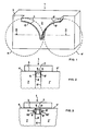
- FIG. 1 shows in isolation a possible configuration for a small face 1 provided with a projection 2, or insert, intended to penetrate inside the inter-cylinder space.
- This insert is incorporated by construction into the small face, or is attached to its front face 3 which is adjusted against the front surfaces of the cylinders when the small face is installed on the machine.
- the contours 4, 4 ′ of the front surfaces of the cylinders are shown in dotted lines in FIG. 1.
- the insert has two curved cuts 5, 5 ′ matching the shape of the cylinders. According to the invention, in the configuration shown, the surfaces of these cutouts 5, 5 ′ are each coated with a film 6, 6 ′ intended to seal the contact between the cylinders and the surfaces of the cutouts 5, 5 ′. This film must meet different criteria.
- its initial thickness is such that, at the very start of casting, while the cylinders are cold, the clearance between the film and the cylinder facing it does not exceed 0.1 mm in order to avoid infiltration of molten metal between the cylinder and the cutout.
- the cylinder expands and rubs against the film, the latter decreases in thickness due to wear and / or compression. This decrease naturally follows the expansion of the cylinder envelope, since the variation in thickness of the film is linked to the pressure exerted by the expansion.
- the film When the cylinder has reached its maximum expansion which it will keep for the remainder of the casting if the operating conditions remain stable, the film must be completely consumed, or have a stable residual thickness, so that the clearance between the cylinder and the cutout still does not exceed 0.1 mm.
- the cutout of the insert can itself be coated with a metal sheet (not shown) intended to reduce the wear of the insert in contact with the cylinders.
- the sealing film 6, 6 ′ is then deposited on this metal sheet.
- Figure 2 shows the small face 1, which has just been described, mounted in a continuous casting machine of which a portion of the cylinders 7, 7 'is shown. We see in particular the side surfaces 8, 8 ′ of the cylinders rubbing against the films 6, 6 ′.
- the film 6, 6 ′ may not be deposited on the cutouts of the insert of the small faces, but on the cylinders themselves prior to casting, as shown in FIG. 3. Each film thus forms a ring surrounding one end of a cylinder. It is then advisable to dig, on the lateral surfaces 8, 8 ′ of the cylinders, grooves 9, 9 ′ in each of which comes a protuberance 10, 10 ′ formed on the internal face of the film 6, 6 ′. This arrangement ensures lateral retention of the films 6, 6 ′ during the rotation of the cylinders, when the films rub against the lateral surfaces 5, 5 ′ of the insert 2.
- the groove or the surface of the cylinders may also include means, such as aliasing or asperities, serving to avoid or limit the sliding of the film on the cylinder.
- the film may be made of a material which can be consumed by wear such as carbon or cellulose fibers.
- the decrease in film thickness can also be the result mainly of the compression force exerted on it by the cylinder and the insert.
- the use of a metal softer than copper, such as aluminum or lead is then very suitable.
- the invention is not limited to the example which has just been described and shown. Different other configurations of the insert and of the whole of the small face are possible, the main thing being the presence of sealing films with decreasing thickness over time between the cylinders and the lateral surfaces of the inserts, as the thermal regime of the casting cylinders.
Landscapes
- Engineering & Computer Science (AREA)
- Mechanical Engineering (AREA)
- Continuous Casting (AREA)
- Cylinder Crankcases Of Internal Combustion Engines (AREA)
- Coating With Molten Metal (AREA)
Applications Claiming Priority (2)
| Application Number | Priority Date | Filing Date | Title |
|---|---|---|---|
| FR8917292 | 1989-12-26 | ||
| FR8917292A FR2656244A1 (fr) | 1989-12-26 | 1989-12-26 | Dispositif de coulee continue de produits metalliques minces entre deux cylindres refroidis en rotation. |
Publications (1)
| Publication Number | Publication Date |
|---|---|
| EP0435729A1 true EP0435729A1 (de) | 1991-07-03 |
Family
ID=9389040
Family Applications (1)
| Application Number | Title | Priority Date | Filing Date |
|---|---|---|---|
| EP90403562A Withdrawn EP0435729A1 (de) | 1989-12-26 | 1990-12-12 | Vorrichtung zum Stranggiessen von dünnen metallischen Produkten zwischen zwei gekühlten rotierenden Zylindern |
Country Status (21)
| Country | Link |
|---|---|
| US (1) | US5154222A (de) |
| EP (1) | EP0435729A1 (de) |
| JP (1) | JPH04270034A (de) |
| KR (1) | KR910011368A (de) |
| CN (1) | CN1054551A (de) |
| AR (1) | AR244584A1 (de) |
| AU (1) | AU634841B2 (de) |
| BR (1) | BR9006506A (de) |
| CA (1) | CA2032065A1 (de) |
| CZ (1) | CZ278031B6 (de) |
| FI (1) | FI906309A7 (de) |
| FR (1) | FR2656244A1 (de) |
| HU (1) | HU206288B (de) |
| IE (1) | IE904472A1 (de) |
| NO (1) | NO905550L (de) |
| PE (1) | PE9391A1 (de) |
| PL (1) | PL288416A1 (de) |
| PT (1) | PT96232A (de) |
| RU (1) | RU1834744C (de) |
| YU (1) | YU245390A (de) |
| ZA (1) | ZA9010330B (de) |
Families Citing this family (5)
| Publication number | Priority date | Publication date | Assignee | Title |
|---|---|---|---|---|
| AT412195B (de) * | 2002-06-25 | 2004-11-25 | Voest Alpine Ind Anlagen | Verfahren zur erzeugung eines metallbandes mit einer zweiwalzengiesseinrichtung |
| FR2842130B1 (fr) * | 2002-07-12 | 2004-10-15 | Usinor | Face laterale pour installation de coulee continue de bandes metalliques entre deux cylindres |
| RU2278000C2 (ru) * | 2004-08-18 | 2006-06-20 | Марсиль Робертович Ахметшин | Способ производства металлического волокна |
| US8042601B2 (en) * | 2006-03-24 | 2011-10-25 | Nucor Corporation | Side dam with insert |
| CN104722726B (zh) * | 2013-12-23 | 2017-03-29 | 鞍钢股份有限公司 | 一种高硅电工钢连铸生产方法 |
Citations (1)
| Publication number | Priority date | Publication date | Assignee | Title |
|---|---|---|---|---|
| EP0285963A2 (de) * | 1987-04-08 | 1988-10-12 | Nisshin Steel Co., Ltd. | Stranggusseinrichtung für Metallbänder |
Family Cites Families (10)
| Publication number | Priority date | Publication date | Assignee | Title |
|---|---|---|---|---|
| JPS58179543A (ja) * | 1982-04-13 | 1983-10-20 | Mitsubishi Heavy Ind Ltd | 金属薄板の連続鋳造装置 |
| JPS6033859A (ja) * | 1983-08-05 | 1985-02-21 | Mitsubishi Heavy Ind Ltd | 薄板連続鋳造装置 |
| CH664916A5 (de) * | 1984-04-18 | 1988-04-15 | Concast Service Union Ag | Vorrichtung zum seitlichen abschliessen eines formhohlraumes mit im wesentlichen rechteckigem querschnitt in einer stranggiessanlage. |
| JPS6130260A (ja) * | 1984-07-23 | 1986-02-12 | Nippon Steel Corp | 双ロ−ル鋳造用溶融金属注入装置 |
| JPS6221444A (ja) * | 1985-07-22 | 1987-01-29 | Mitsubishi Heavy Ind Ltd | 薄板連続鋳造方法 |
| JPS6221445A (ja) * | 1985-07-23 | 1987-01-29 | Ishikawajima Harima Heavy Ind Co Ltd | ベルト式連続鋳造機 |
| JPS6240955A (ja) * | 1985-08-20 | 1987-02-21 | Mitsubishi Heavy Ind Ltd | 薄板連続鋳造装置 |
| FR2636259B1 (fr) * | 1988-09-14 | 1994-03-11 | Irsid | Paroi laterale pour une installation de coulee continue entre parois mobiles et installation comportant cette paroi |
| DE3926719A1 (de) * | 1988-12-23 | 1990-07-05 | Bayer Ag | Polycarbonate aus alkylcyclohexylidenbisphenolen |
| FR2651454A1 (fr) * | 1989-09-01 | 1991-03-08 | Siderurgie Fse Inst Rech | Dispositif de coulee continue de metal liquide entre deux cylindres paralleles. |
-
1989
- 1989-12-26 FR FR8917292A patent/FR2656244A1/fr active Pending
-
1990
- 1990-12-10 CZ CS906148A patent/CZ278031B6/cs unknown
- 1990-12-11 IE IE447290A patent/IE904472A1/en unknown
- 1990-12-11 US US07/625,854 patent/US5154222A/en not_active Expired - Fee Related
- 1990-12-12 EP EP90403562A patent/EP0435729A1/de not_active Withdrawn
- 1990-12-12 CA CA002032065A patent/CA2032065A1/fr not_active Abandoned
- 1990-12-14 AR AR90318630A patent/AR244584A1/es active
- 1990-12-18 PT PT96232A patent/PT96232A/pt not_active Application Discontinuation
- 1990-12-20 FI FI906309A patent/FI906309A7/fi not_active Application Discontinuation
- 1990-12-20 AU AU68275/90A patent/AU634841B2/en not_active Ceased
- 1990-12-20 BR BR909006506A patent/BR9006506A/pt unknown
- 1990-12-21 NO NO90905550A patent/NO905550L/no unknown
- 1990-12-21 HU HU908409A patent/HU206288B/hu not_active IP Right Cessation
- 1990-12-21 PL PL28841690A patent/PL288416A1/xx unknown
- 1990-12-21 ZA ZA9010330A patent/ZA9010330B/xx unknown
- 1990-12-22 KR KR1019900021465A patent/KR910011368A/ko not_active Withdrawn
- 1990-12-25 CN CN91100615A patent/CN1054551A/zh active Pending
- 1990-12-25 YU YU245390A patent/YU245390A/sh unknown
- 1990-12-25 RU SU904894068A patent/RU1834744C/ru active
- 1990-12-26 JP JP2414411A patent/JPH04270034A/ja not_active Withdrawn
- 1990-12-26 PE PE1990179660A patent/PE9391A1/es unknown
Patent Citations (1)
| Publication number | Priority date | Publication date | Assignee | Title |
|---|---|---|---|---|
| EP0285963A2 (de) * | 1987-04-08 | 1988-10-12 | Nisshin Steel Co., Ltd. | Stranggusseinrichtung für Metallbänder |
Non-Patent Citations (1)
| Title |
|---|
| PATENT ABSTRACTS OF JAPAN, vol. 9, no. 158 (M-393)[1881], 3 juillet 1985; & JP-A-60 033 859 (MITSUBISHI JUKOGYO K.K.) 21-02-1985 * |
Also Published As
| Publication number | Publication date |
|---|---|
| KR910011368A (ko) | 1991-08-07 |
| HU206288B (en) | 1992-10-28 |
| AU634841B2 (en) | 1993-03-04 |
| FI906309A0 (fi) | 1990-12-20 |
| NO905550D0 (no) | 1990-12-21 |
| PL288416A1 (en) | 1991-09-23 |
| PT96232A (pt) | 1991-09-30 |
| NO905550L (no) | 1991-06-27 |
| JPH04270034A (ja) | 1992-09-25 |
| ZA9010330B (en) | 1992-07-29 |
| AU6827590A (en) | 1991-07-04 |
| BR9006506A (pt) | 1991-10-01 |
| CZ278031B6 (en) | 1993-07-14 |
| US5154222A (en) | 1992-10-13 |
| FI906309A7 (fi) | 1991-06-27 |
| HUT56016A (en) | 1991-07-29 |
| FR2656244A1 (fr) | 1991-06-28 |
| PE9391A1 (es) | 1991-03-22 |
| RU1834744C (ru) | 1993-08-15 |
| YU245390A (sh) | 1993-11-16 |
| AR244584A1 (es) | 1993-11-30 |
| IE904472A1 (en) | 1991-07-03 |
| CN1054551A (zh) | 1991-09-18 |
| CA2032065A1 (fr) | 1991-06-27 |
| CS614890A3 (en) | 1992-02-19 |
Similar Documents
| Publication | Publication Date | Title |
|---|---|---|
| EP0698433B1 (de) | Doppelroll Stanggiessmaschine mit angedrückten Seitenwände | |
| EP0894556B1 (de) | Seitenwand für eine Zweirollenstranggiessanlage zur Herstellung von dünnen Metallbändern | |
| EP0366505B1 (de) | Kolbenschutzkappe | |
| FR2625928A1 (fr) | Plaque obturatrice pour fermeture a coulisse d'un recipient metallurgique, et fermeture a coulisse comportant de telles plaques | |
| EP0435729A1 (de) | Vorrichtung zum Stranggiessen von dünnen metallischen Produkten zwischen zwei gekühlten rotierenden Zylindern | |
| CA2193243C (fr) | Face laterale pour une machine de coulee en continu de tole mince | |
| EP0567374B1 (de) | Spenderkappe für flüssige oder pastöse Produkte | |
| EP0432073A1 (de) | Einrichtung zum Stranggiessen von dünnen metallischen Produkten zwischen zwei Walzen | |
| FR2787155A1 (fr) | Agencement d'etancheite pour un joint homocinetique, et procede de fabrication correspondant | |
| CA2050112C (fr) | Installation de coulee continue entre cylindres | |
| EP0759335A1 (de) | Stützvorrichtung für die Seitenwände einer Walzenstranggiessanlage zum Herstellen metallischer Bänder | |
| EP0406142B1 (de) | Kassette, bestimmt zum Abschliessen der Stirnseite einer Stranggiessanlage | |
| FR2695580A1 (fr) | Dispositif de coulée continue entre cylindres de produits métalliques minces. | |
| EP0552125A1 (de) | Doppelrollen Stranggiessanlage mit feuerfesten Seitenwänden | |
| FR2650966A1 (fr) | Procede et dispositif de coulee continue directe de produits metalliques minces | |
| EP0561724A1 (de) | Doppelrollen-Stranggiessvorrichtung zum Giessen von metallischen Produkten | |
| FR2723013A1 (fr) | Face laterale pour une machine de coulee en continu de tole mince | |
| CH366636A (fr) | Organe de machine et procédé pour sa fabrication | |
| FR2499304A1 (fr) | Procede de fixation d'une armature metallique sur un dielectrique d'isolateur | |
| EP0142402A1 (de) | Anlage zum horizontalen Stranggiessen von Metallen, insbesondere von Stahl | |
| FR2745210A1 (fr) | Unite coulissante pour un conteneur metallurgique, et plaque associee | |
| FR2613646A1 (fr) | Dispositif d'obturation laterale pour lingotiere de coulee continue entre cylindres | |
| EP0171487A1 (de) | Vorrichtung zum Aussenabschluss eines Gefässes für schmelzflüssige Metalle | |
| FR2785211A1 (fr) | Face laterale pour installation de coulee continue de bandes metalliques entre deux cylindres | |
| EP0552124A1 (de) | Vorrichtung zum Stranggiessen eines Metallproduktes zwischen Giesswalzen |
Legal Events
| Date | Code | Title | Description |
|---|---|---|---|
| PUAI | Public reference made under article 153(3) epc to a published international application that has entered the european phase |
Free format text: ORIGINAL CODE: 0009012 |
|
| AK | Designated contracting states |
Kind code of ref document: A1 Designated state(s): AT BE CH DE DK ES GB GR IT LI LU NL SE |
|
| 17P | Request for examination filed |
Effective date: 19911114 |
|
| 17Q | First examination report despatched |
Effective date: 19930402 |
|
| STAA | Information on the status of an ep patent application or granted ep patent |
Free format text: STATUS: THE APPLICATION HAS BEEN WITHDRAWN |
|
| 18W | Application withdrawn |
Withdrawal date: 19930809 |