EP0437620A1 - Corps de bouteille fabrique en resine synthetique - Google Patents
Corps de bouteille fabrique en resine synthetique Download PDFInfo
- Publication number
- EP0437620A1 EP0437620A1 EP90910181A EP90910181A EP0437620A1 EP 0437620 A1 EP0437620 A1 EP 0437620A1 EP 90910181 A EP90910181 A EP 90910181A EP 90910181 A EP90910181 A EP 90910181A EP 0437620 A1 EP0437620 A1 EP 0437620A1
- Authority
- EP
- European Patent Office
- Prior art keywords
- wall
- container
- flat
- bottle
- circumferential groove
- Prior art date
- Legal status (The legal status is an assumption and is not a legal conclusion. Google has not performed a legal analysis and makes no representation as to the accuracy of the status listed.)
- Granted
Links
Images


Classifications
-
- B—PERFORMING OPERATIONS; TRANSPORTING
- B65—CONVEYING; PACKING; STORING; HANDLING THIN OR FILAMENTARY MATERIAL
- B65D—CONTAINERS FOR STORAGE OR TRANSPORT OF ARTICLES OR MATERIALS, e.g. BAGS, BARRELS, BOTTLES, BOXES, CANS, CARTONS, CRATES, DRUMS, JARS, TANKS, HOPPERS, FORWARDING CONTAINERS; ACCESSORIES, CLOSURES, OR FITTINGS THEREFOR; PACKAGING ELEMENTS; PACKAGES
- B65D1/00—Rigid or semi-rigid containers having bodies formed in one piece, e.g. by casting metallic material, by moulding plastics, by blowing vitreous material, by throwing ceramic material, by moulding pulped fibrous material or by deep-drawing operations performed on sheet material
- B65D1/02—Bottles or similar containers with necks or like restricted apertures, designed for pouring contents
- B65D1/0223—Bottles or similar containers with necks or like restricted apertures, designed for pouring contents characterised by shape
- B65D1/0261—Bottom construction
- B65D1/0276—Bottom construction having a continuous contact surface, e.g. Champagne-type bottom
-
- B—PERFORMING OPERATIONS; TRANSPORTING
- B65—CONVEYING; PACKING; STORING; HANDLING THIN OR FILAMENTARY MATERIAL
- B65D—CONTAINERS FOR STORAGE OR TRANSPORT OF ARTICLES OR MATERIALS, e.g. BAGS, BARRELS, BOTTLES, BOXES, CANS, CARTONS, CRATES, DRUMS, JARS, TANKS, HOPPERS, FORWARDING CONTAINERS; ACCESSORIES, CLOSURES, OR FITTINGS THEREFOR; PACKAGING ELEMENTS; PACKAGES
- B65D1/00—Rigid or semi-rigid containers having bodies formed in one piece, e.g. by casting metallic material, by moulding plastics, by blowing vitreous material, by throwing ceramic material, by moulding pulped fibrous material or by deep-drawing operations performed on sheet material
- B65D1/02—Bottles or similar containers with necks or like restricted apertures, designed for pouring contents
- B65D1/0223—Bottles or similar containers with necks or like restricted apertures, designed for pouring contents characterised by shape
-
- B—PERFORMING OPERATIONS; TRANSPORTING
- B65—CONVEYING; PACKING; STORING; HANDLING THIN OR FILAMENTARY MATERIAL
- B65D—CONTAINERS FOR STORAGE OR TRANSPORT OF ARTICLES OR MATERIALS, e.g. BAGS, BARRELS, BOTTLES, BOXES, CANS, CARTONS, CRATES, DRUMS, JARS, TANKS, HOPPERS, FORWARDING CONTAINERS; ACCESSORIES, CLOSURES, OR FITTINGS THEREFOR; PACKAGING ELEMENTS; PACKAGES
- B65D2501/00—Containers having bodies formed in one piece
- B65D2501/0009—Bottles or similar containers with necks or like restricted apertures designed for pouring contents
- B65D2501/0018—Ribs
- B65D2501/0036—Hollow circonferential ribs
-
- B—PERFORMING OPERATIONS; TRANSPORTING
- B65—CONVEYING; PACKING; STORING; HANDLING THIN OR FILAMENTARY MATERIAL
- B65D—CONTAINERS FOR STORAGE OR TRANSPORT OF ARTICLES OR MATERIALS, e.g. BAGS, BARRELS, BOTTLES, BOXES, CANS, CARTONS, CRATES, DRUMS, JARS, TANKS, HOPPERS, FORWARDING CONTAINERS; ACCESSORIES, CLOSURES, OR FITTINGS THEREFOR; PACKAGING ELEMENTS; PACKAGES
- B65D2501/00—Containers having bodies formed in one piece
- B65D2501/0009—Bottles or similar containers with necks or like restricted apertures designed for pouring contents
- B65D2501/0081—Bottles of non-circular cross-section
Definitions
- the present invention relates to a large bottle made of synthetic resin, particularly relates to the body wall structure of a large square bottle made of polyethylene terephthalate (hereinafter referred to as "PET”) biaxially oriented blow molded, the structure from a body upper end to a shoulder and the wall structure of a ridge-line portion which gives a serious influence upon the external appearance and configuration of a bottle by bending and connecting two wall surface portions.
- PET polyethylene terephthalate
- the biaxial oriented blow molded bottle of polyethylene terephthalate resin is excellent in various durabilities such as content resistance, chemical resistance, weather resistance, and further shock resistance and the like, and has high mechanical strength, transparency, no pollution and further gas barrier properties. Therefore, such a bottle has been used on a large scale for containing various kind of liquid.
- This PET biaxial oriented blow molded large bottle is not sufficient enough in mechanical strength of its body such as self configuration sustaining capability or buckling strength since the body as a main portion of the bottle is thin in thickness.
- a bottle having a square cylindrical body is poor in not only buckling strength but also self configuration sustaining capability. Therefore, there is in convenience such that a large incorrect depressed deformation at the body is caused by negative pressure generated within the bottle after a liquid is contained and sealed therein.
- a central circumferential groove is provided at a substantial center of the body for increasing buckling strength against depression force applied on the bottle from the outside, and increasing self configuration sustaining capability of the body against external force applied in the diametrical direction, and at the central portion of a flat wall divided into the upper and lower portions by the central circumferential groove is provided a recessed portion having a depression deformable shaped panel wall as a bottom wall for taking up negative pressure generated in the bottle by a certain depression deformation at this shaped panel wall to prevent any incorrect depression deformation from occurring in the body, and increasing self configuration sustaining capability of the flat wall portion.
- the increase of mechanical configuration sustaining capability by providing the central circumferential groove and the recessed portion formed with the shaped panel wall can be obtained by acting inclined groove sidewalls of the central circumferential groove and inclined groove sidewalls of the recessed portion as reinforcing rib wall pieces with respect to the diametrical direction of the body.
- the self configuration sustaining capability of the body of the bottle, particularly the vicinity of the central circumferential groove grasped by the hand is actively reinforced by setting the oblique angles of the groove sidewalls and recessed sidewalls large values, but when more than certain pressure is applied to the body of the bottle at the time of handling the bottle or at the time of casing and transporting bottles, the portion from the groove sidewalls and recessed sidewalls to the flat wall is sharply bent and/or depressedly deformed, and the deformed portion does not return to the original configuration even if the pressure is removed, and the bent and/or depressed deformation becomes permanent deformation to cause such a problem that a commercial value of the bottle is lost.
- the above-described conventional negative pressure taking up recessed portion is constructed by forming the shaped panel wall as its bottom wall into a shape which is easily deformable by negative pressure, and absorbing negative pressure generated in the bottle by large depressed deformation at the central portion of the shaped panel wall, so that the negative pressure deformation of this shaped panel wall appears as external appearance of the bottle, that is a problem to lower external appearance and style of the bottle as a goods.
- the shaped panel wall occupying a large surface area at each flat wall of the body is liable to deform, so that when grasping the bottle by the hand, the deformed panel wall where finger tips are made into contact is easily deformed, and the bottle becomes unstable to handle by the hand.
- the shaped panel wall occupies the large surface area of each flat wall of the body, but the wall structure of this shaped panel wall is mainly of a deformable flat structure, so that its external appearance becomes simple, that is a problem to make external appearance of the bottle dull.
- the concave and convex shaped panel wall is molded at the flat wall portion of the body of the PET large square bottle, so that it is extremely difficult to print a commercial name or a company name or to stick and display a label, and hence, the commercial name or the company name is displayed with the aid of a shrunk label made of a heat-shrinkable sheet.
- this shrunk label is originally a simple sheet, it is easy to print pattern and display and to form into a cylindrical body, and it is further advantageous to strongly attach to the bottle by simple but secure heat treatment, but because of certain shrinking deformation made of a heat-shrinkable sheet, the portion opposed to the flat wall of the square cylinder has large shrinkage as compared with the portion opposed to the ridge-line, and as a result, the end of a shrunk label wound around the bottle is wrinkled to deteriorate external appearance and style as a goods.
- the shoulder portion which extension is not sufficient as compared with the body is a square cylinder, there is generated a large difference of extension between the ridge line of the shoulder and the flat wall portion, resulting in incorrect thermal deformation at the shoulder portion by this non-uniform extension.
- the PET bottle has excellent transparency, but as compared with a glass bottle exhibiting the same excellent transparent feeling, the PET bottle is simply clear, but does not exhibit any crystal effect due to deflection of transmitted light, so as to be poor in visual change.
- a first object of the invention is to exhibit function of the groove sidewall of a central circumferential groove and the recess sidewall of a recessed portion as reinforcing rib wall pieces, and to make the deformation not bending depressed deformation but self recoverable curve depressed deformation at the time of depressed deformation.
- Another object of the invention is to prevent appearance of reduced pressure deformation as a change of external appearance and shape of the bottle and to prevent deterioration of external appearance and style of the bottle by attaining reduced pressure taking up deformation of a shaped panel wall for taking up negative pressure generated in the bottle by depressed deformation of the whole shaped panel wall.
- a further object of the invention is to increase self configuration retaining capability of the shaped panel wall itself and to give external appearance interest.
- a more further object of the invention is to remove or minimize corrugation at the upper edge of a shrunk label conspicuous as external appearance of the bottle as a goods by positioning in the vicinity of the shoulder portion of the bottle, and to minimize non-uniformity of extension along the circumferential direction at the shoulder portion as small as possible.
- the other object of the invention is to exhibit enough crystal effect in the PET bottle without increasing a thickness of the PET bottle.
- a biaxially oriented blow-molded bottle-shaped container made of synthetic resin; said container comprising a rectangular cylindrical body provided with a central circumferential groove substantially at a center of a vertical length of the rectangular cylindrical body; the central circumferential groove having upper and lower sidewalls; these sidewalls being inclined at an oblique angle within a range of 21° -28° with respect to a vertical longitudinal axis of the container.
- the oblique angle with respect to the bottle center axis of the groove sidewall is not measured from the same direction with respect to the bottle central axis but measured from an acute angle with respect to the bottle central axis, so that the oblique angle of the upper groove sidewall and that of the lower groove sidewall are measured from opposite directions.
- the central circumferential groove is depressedly provided at a substantially central portion of the body, so that the wall portion for connecting the upper and lower groove sidewalls and the flat wall is curved and projected on the bottle surface. Therefore, the groove sidewall functions to pressure acting on the central circumferential groove portion as a reinforcing rib wall piece, so as to prevent the body wall portion where pressure is acted from simple depressed deformation, and when strong pressure force is acted to generate depressed deformation, the junction portion for connecting the groove sidewall and flat wall becomes reverse depressed deformation for reversing the projection posture.
- the junction portion for connecting the center peripheral groove and flat wall becomes reversed depressed deformation in the same manner as the prior bottle, but in the case of the present invention, the oblique angle of the groove sidewall is small, so that the whole junction portion for connecting the groove sidewall and the flat wall is curved and depressedly deformed, the oblique angle of the groove sidewall and the flat wall is sufficiently reduced by this depressed deformation, and the central portion which is depressed by a pressing force before a depressed amount become large is reversely curved and deformed.
- upper and lower groove sidewalls of the central circumferential wall are set at oblique angles for exhibiting function as reinforcing rib wall pieces as large as possible within the range of generating no bent reverse deformation, and setting of the oblique angle of the groove sidewall is sought from many experimental examples, and according to the experimental examples, if the oblique angle of the groove sidewall is set at more than about 29°, self configuration sustaining capability becomes large, the whole junction portion between the groove sidewalls and the flat wall when applying pressure becomes hard to cause curve depressed deformation, and as a result, depressed deformation at the junction portion becomes rapid reverse bending and self configuration sustaining capability cannot be obtained.
- the oblique angle of the groove sidewall is set at less than about 20°, the groove sidewall cannot sufficiently functions as a reinforcing rib wall piece, self configuration sustaining capability is low, so that it is difficult to handle the bottle by grasping by the hand.
- the depressed sidewall of the recessed portion provided at the central portion of the flat wall in the same manner as the groove sidewall of the central circumferential groove and its bottom wall being a shaped panel wall for absorbing reduced pressure deformation effectively functions to retain self configuration of the body, but in the recess sidewall, the recessed sidewall portion positioned near the central circumferential groove employs an elongated projected curved wall structure, so that it is difficult to depression deformed under the curved condition, but in the same manner as the groove sidewall of the central circumferential groove, the oblique angle of the recess sidewall portion positioned near the central circumferential groove is set at 28° -21° , so that it becomes easy to generate curved deformation from the groove sidewall to the flat wall and function the recess sidewall as a whole, so as to effectively prevent generation of local reverse bent deformation.
- the length of the recess sidewall is shorter than that of the groove sidewall of the central circumferential groove at the flat wall, reverse curve deformation is mainly generated on the side of the groove sidewall, and the recess sidewall is curved depressedly deformed without any difficulty following to reverse curved deformation of the groove sidewall.
- the depth of the central circumferential groove can be made shallow by connecting upper and lower groove sidewall of the central circumferential groove by means of a groove bottom wall of the flat wall structure, but under a certain dimensional limitation such as a certain groove width of the central circumferential groove, limitation of the oblique angles of the groove sidewall and the recess sidewall results in a shallow depth of the central circumferential groove and the recessed portion.
- a certain dimensional limitation such as a certain groove width of the central circumferential groove
- limitation of the oblique angles of the groove sidewall and the recess sidewall results in a shallow depth of the central circumferential groove and the recessed portion.
- a biaxially oriented blow-molded bottle-shaped container made of synthetic resin, said container comprising a rectangular cylindrical body including flat walls; each of the flat walls having a central recessed portion having a bottom wall comprising a shaped panel wall for taking up deformation due to reduced pressure in the container, and a shaped peripheral groove invertedly curved around the shaped panel wall; the shaped panel wall having ribs traversing the shaped panel wall in parallel to each other, a crest of each of ribs having larger radius of curvature than that of a root thereof; and opposite ends of the root being shallow along a large radius of curvature.
- the shaped panel wall is consisting of a number of transversal ribs, the shaped panel wall is liable to curve in the vertical direction, but hardly curve in the lateral direction by functioning as a reinforcing rib.
- the shaped peripheral groove molded around the shaped panel wall has a reverse curved wall structure, so that it is easily deformed in the curved direction, that is, the vertical direction with respect to the flat wall surface.
- the shaped panel wall is largely curved along the vertical direction, and also curved the shaped central circumferential groove to depress and displace as the whole within the bottle, so as to take up the reduced pressure with sufficient volume.
- the shaped panel wall can be deformed with a large curve in the vertical direction and also depressed or displaced as the whole in order to take up the reduced pressure generated in the container, so that the deformation due to the reduced pressure does not appear as the external appearance.
- the shaped panel wall has a number of ribs extending transversely. These ribs serve as reinforcing ribs and have a sufficient strength to support urging pressure applied by finger tips and to generate an appropriate friction resistance force between the bottle and finger tips when the bottle is grasped by the hand.
- the rib is consisted of crest and root portions and these portions are formed by the curved wall structure, respectively, so that their moldability in blow molding is excellent.
- Each of opposite ends of the root portion is made gradually shallow along a curve having a large radius of curvature so that the corner portion between the flat walls is improved in moldability.
- the ribs thus forming the shaped panel wall provide a number of small concaves and convexes on the surface of the shaped panel wall and therefore the shaped panel wall has substantially different wall thickness in any direction owing to the many ribs. Consequently, when the bottle is made of a clear synthetic resin having high transparency such as polyethylene terephthalate, an optical crystal sense appears in the external appearance of the shaped panel wall by the large variation of wall thickness.
- the degree of the concave and convex shape of the shaped panel wall can be made deep and as a result the self configuration sustaining capability in the transverse direction of the shaped panel wall is improved and the appeared crystal sense is enhanced.
- a biaxially oriented blow-molded bottle-shaped container made of synthetic resin; said container comprising a rectangular cylindrical body having an upper end which is a regular polygon having corners of two times numbers of corners of a main portion of the body, and a shoulder having a lower end portion connected to the upper end of the body; the lower end portion of the shoulder being in the form of a regular polygonal truncated pyramid shape having corners of two times numbers of corners of the main portion of the body.
- the shrunk label is generally applied to the bottle in a range from the upper half portion to the lower end portion of the shoulder and therefore the upper edge of the shrunk label applied to the bottle is located at the lower end portion of the shoulder and the opposed lower edge is located in the central circumferential groove.
- the shrunk label is applied around the bottle in such a manner that the upper edge is wound around the reduced lower end portion of the shoulder and the lower edge is also wound around the reduced portion in the central circumferential groove. Therefore, both the upper and lower edges are located in corresponding upper and lower portions of reduced diameters, respectively so that the shrunk label is prevented from drawing out the bottle and is strongly and stably secured to the bottle.
- the lower end portion of the shoulder where the upper edge portion of the shrunk label is wound has the regular polygonal shape and corners of two times numbers of corners of the main portion of the body and furthermore, the lower end portion has smaller diameter than that of the main portion of the body. Therefore, the upper edge portion of the shrunk label which is wound around the lower end portion of the shoulder is under a condition that a difference of shrinkage between a portion faced to the ridge-line of the lower end portion of the shoulder and a portion faced to the flat wall is small and the shrinkage of portion faced to the lower end portion is uniform, and furthermore any displacement to be resulted from the shrinkage of the shrunk label in the vertical direction is prevented by the upper end portion of the body which has larger diameter. Accordingly, in the upper edge portion of the shrunk label wound around the lower end portion of the shoulder, any large wrinkle does not occur.
- the central portion of the body where the lower edge of the shrunk label is wound has a rectangular cylindrical shape. Therefore, the lower edge portion of the shrunk label is under a condition that there is some different of shrinkage between a portion faced to the ridge-line of the central portion of the body and a portion faced to the flat wall, as a result, the lower edge portion of the shrunk label is wrinkled.
- the central circumferential groove is provided at the central portion of the body and the lower edge of the shrunk label is located in the central circumferential groove.
- a portion of the shrunk label at just above the lower edge located in the central circumferential groove is initially applied to the surface of the body and then prevents any displacement of the lower edge portion to be resulted from the shrinkage of the shrunk label in the vertical direction. Consequently, any large wrinkle does not occur at the lower edge of the shrunk label, too.
- the lower end portion of the shoulder is molded in the shape of regular polygon, average elongation of each combination of the flat wall and ridge-line portion at the lower end portion of the shoulder is the same, and since the lower end portion of the shoulder has corners of two times numbers of corners of the main portion of the body, the difference of elongation between the flat wall portion and the ridge-line portion is sufficiently small. Accordingly, the lower end portion of the shoulder can be uniformly molded with substantially the same elongation.
- the lower end portion of the shoulder is uniformly elongated in the circumferential direction during blow molding, even if thermal deformation occurs in the shoulder portion due to insufficient elongation, the thermal deformation uniformly occurs in the circumferential direction and therefore irregular deformation does not appear in the external appearance of the shoulder portion due to the thermal deformation.
- a biaxially oriented blow-molded bottle-shaped container made of synthetic resin having a high clarity; said container including two sets of wall surface portions of first wall surface portions and second wall surface portions which are formed at the shoulder and the bottom, respectively, and are connected through a curved lines to each other; a connecting edge of the first wall surface portion connected to the second wall surface portion being slightly extended toward the second wall surface portion; the extended edge of the first wall surface portion being connected to a connecting edge of the second wall surface portion through a ridge-line wall portion which is reversely curved with a small radius of curvature.
- the first wall surface portion and the second wall surface portion which are connected at the ridge-line wall portion are not specified in respect to individual wall structure and a combination of mutual wall structures, but at least one of the wall surface portions is preferably a flat wall surface structure, and particularly the first wall surface portion may be a flat wall structure and the second wall surface portion may be curved wall structure.
- the connecting edge of the first wall surface portion is slightly extended and this extended edge of the first wall surface portion is connected to the connecting edge of the second wall surface portion at the ridge-line wall portion, the curved line, i.e. ridge-line portion formed between both the wall surface portions forms a protruded ridge-line which is protruded in the direction of the extended connecting edge of the first wall surface portion.
- the protruded ridge-line portion is more sharply protruded than that of the usual ridge-line portion to thereby enhance the difference of the refraction direction of the transmitted light through each of both the wall surface portions which have different angles of inclination starting from the protruded ridge-line.
- the ridge-line wall portion of the protruded ridge-line is reversed with a curve of small radius of curvature to locate it in an attitude substantially standing to the transmitted light passing in the direction of thickness of both of the wall surface portion, thereby the ridge-line wall portion provides a locally thickened wall portion for the transmitted light by the ridge-line wall portion. It will be seen from the above that since the ridge-line wall portion provides a locally thickened wall portion for the transmitted light, the transmitted light passing through the ridge-line wall portion is subjected to greater refraction than that of transmitted light passing through the adjacent other portion, i.e. both the wall surface portions.
- both the adjacent wall surface portion is the flat wall structure, particularly the first wall surface portion is the flat wall structure and the second wall surface portion is the curved wall structure, amount of extending of the protruded ridge-line can be increased within a narrow range to thereby provide relatively strong refracting action for the transmitted light and the radius of curvature of the reversed curve of the ridge-line wall portion can be slightly increased, thereby the bottle can be easily molded.
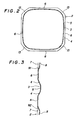
- a bottle 1 has a body 2 formed in the form of a square cylinder.
- the body has four ridged-line walls 13 at corners thereof, respectively, each of which is formed by an arched wall having a radius of curvature of a length of a half of a diagonal line.
- the body has also a central circumferential groove 3 which is formed at a central position slightly higher than a half level of the whole height to divide each of four flat walls 6 into upper and lower half portions, respectively.
- the body further has a bottom having a central curved recess retracted inwardly into the bottle 1 and an upper end portion having a diameter which is gradually reduced from a shoulder 11 having a semispherical shape and has an opening 12 at the upper end thereof.
- Each of the upper and lower portions of the flat wall 6 divided by the central circumferential groove 3 has a recessed portion 7 formed at the center portion thereof.
- the recessed portion 7 has a shaped bottom panel wall 8 at the central portion thereof and a deformed sidewall 9 at the peripheral portion of the recessed portion 7.
- a portion of the sidewall 9 of the recessed portion 7 adjacent to the central circumferential groove 3 that is the upper portion of the sidewall 9 in the lower recessed portion 7 and the lower portion of the side wall in the upper recessed portion 7 are approximately straight extended along the central circumferential groove 3 so that the portions of the flat wall 6 between the central circumferential groove 3 and the recessed portions 7 can be easily bent as the whole.
- the central circumferential groove 3 has a flat bottom wall 5 and corners having a large radius of curvature in the cross section thereof as shown in Fig. 2 so that the central circumferential groove 3 has smaller depth at a portion opposed to the flat wall 6 than that at a portion opposed to the ridge-line wall 13, as a result the portion opposed to the ridge-line wall 13 of the central circumferential groove 3 is hardly deformed, while the portion opposed to the flat wall 6 is easily bent or depressed. Therefore, when portions of the central circumferential groove 3 and the flat wall 6 are bent or deformed by depressing, the ridge-line walls 13 effects as a strong supporting portions so that the deformation of the groove and the flat wall is effected in a stable mode.
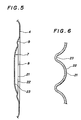
- Fig. 3 illustrates an embodiment of a wall structure near the central circumferential groove 3 in vertical section.
- a bottle 1 including such a wall structure has an internal space of 1.5 litter and is shaped such that the diameter of the lower body portion 7 is larger than that of the upper body portion 7 positioned above the central circumferential groove 3.
- the lower side wall 4 of the central circumferential groove 3 is mainly subjected to a depressing force by grasping when the bottle is handled, the lower side wall 4 of the central circumferential groove 3 is set at the maximum angle of inclination of 27°, while the upper side wall 4 of the central circumferential groove 3 is set at an angle of inclination of 24° and angle of inclination of the sidewall 91, 92 of the recessed portion 7 opposed to the central circumferential groove 3 is set at an angle of 21°.
- the angle of inclination of the groove sidewall 4 and the recess sidewall 91, 92 and their combination may be selectively set in a range of 21° -27°, but since the purpose of providing the central circumferential groove 3 is to enhance the self configuration sustaining capability, preferably the angle of inclination of the lower groove side wall 4 which is subjected to the depression force upon handling of the bottle 1 may be set at the maximum to enhance the self configuration sustaining capability of the body 2 owing to the central circumferential groove 3.
- a number of ribs 21 extending parallel to each other are transversely formed on the shaped panel wall 8. These ribs 21 define crests 22 and roots 23 and the radius of curvature of the crest 22 is set to four times of the radius of curvature of the root 23 to thereby enhance moldability of each of ribs 21.
- the ridge-line of the crest of each of ribs 21 is set to the same height as that of the inner peripheral edge of the deformed peripheral groove 9 so as to connect the opposite ends of the rib to the inner peripheral edges of the deformed peripheral groove 9 directly, respectively, and the opposite ends of the root 23 becomes gradually shallow along a curve having a large radius of curvature to connect to the inner peripheral edges of the deformed peripheral groove 9, respectively.
- the opposite ends of the root 23 is formed gradually shallow along a curve of a large radius of curvature, so that it is capable of enhancing the moldability of the ridge-line wall 13 which is continuously elongated after the flat wall 6 has been deformed during the blow molding of the bottle.
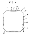
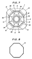
- the upper end portion of the bottle body is preferably shaped to regular polygon having corners of two times of that of the main portion of the body by forming the ridge-line walls at the corners of the upper end portion of the body to shape arched walls to thereby provide a regular polygonal cylindrical shape by the flat walls and the ridge-line walls and then gradually reducing the diameter of the upper end portion of the body to decrease the width of the flat walls and increase the width of the ridge-line walls.
- the diameter of the upper end portion of the body 2 is gradually reduced to decrease the width of the flat walls 6 and increase the width of the ridge-line walls 7 to thereby shape the upper end portion of the body of a regular octagon. It is desirable in view of external appearance and molding that the body is molded in a square cylindrical shape.
- the lower end portion 31 of the shoulder 11 continued to the upper end of the regular octagonal portion of the body 2 has a shape of a low regular octagonal truncated pyramid extended directly from the upper end of the body 2.
- the upper end of the lower end portion 31 is continued to a main portion 33 in the form of a semispherical shell as a remainder of the shoulder 11 through a narrow stage portion 32 and the main portion 33 is provided with an opening 12 at the upper end thereof.
- the lower end portion of the semi-spherical main portion 33 has inclined flat wall portions 34 continued to the flat walls in the lower end portion 31, respectively, and ridge-line 35 are formed in a boundary between the inclined flat wall portions 34 and the semi-spherical surface.
- a shrunk label printed with a display such as a commercial name, a content and the other is applied to the upper half portion defined by the central circumferential groove 3 of the body 2 with the lower edge of the shrunk label being positioned in the central circumferential groove 3 and the upper edge being positioned on the stage portion 32 of the shoulder 11.
- the shrunk label is hardly acknowledged as the external appearance of the bottle, therefore, for example, even if the lower edge of the shrunk label has been slightly wrinkled, the external appearance of the bottle will not be affected by the wrinkle.
- the shrunk label since the upper edge of the shrunk label locates on the stage portion 32 which forms a flat surface along the radial direction, the upper edge of the shrunk label is hardly wrinkled. Moreover, since both the upper and lower edges are located in areas which are sharply reduced in diameter, the shrunk label is very strongly and stably attached to the bottle 1.
- a wall structure arranged according to the fourth aspect of the present invention is applied to the shoulder 11 and the bottom portion 10 of the bottle 1.
- the main portion 33 of the shoulder constitutes the second wall surface portion and the flat wall portion 34 constitutes the first wall surface.
- the peripheral wall of the base portion 10 which is the tapered cylindrical wall portion extending upwardly from the bottom constitutes the second wall surface portions 42 and a flat wall portion 41 which is formed by obliquely cutting the upper half portion of the second wall surface portion 42 and is continued to the flat wall portion of the body 2.
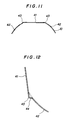
- FIG. 11 An embodiment of the wall structure arranged according to the present invention is illustrated in a sectional view of Fig. 11 which is section taken on line IV-IV in Fig. 9 illustrating the embodiment of the bottom portion 10.
- a portion of a protruded ridge-line 43 shown in Fig. 11 is illustrated in Fig. 12 in enlarged scale.
- a protruding amount of the protruded ridge-line 43 is greatly larger than that of the prior art ridge-line structure and the ridge-line wall portion 44 constituting the protruding ridge-line 43 is bent over with a small radius of curvature to locate a portion of the ridge-line wall portion as a standing rib wall.
- any bent and/or depressed deformations which could not be restored can be perfectly prevented from occurring in the junction between the groove sidewall and the flat wall portion, as a result there is no inconvenience of loss of commercial value of a bottle caused by occurring of bent and/or depressed permanent deformation.
- any bent and/or depressed deformation occurred in the junction between the groove sidewall and the flat wall portion is an elastic deformation in all range of its deformation, when the bottle is grasped by the hand and consequently bent and/or depressed by depressing force, the finger tips of the hand applying the depressing force is always reacted by a rebound so that a stable grasping operation is achieved even if the bent and/or depressed deformation is occurred.
- the depth of the central circumferential groove and the recessed portion can be made shallow and the degree of concave and convex in the body can be made small and therefore the amount of elongation in the flat wall portion can be uniformized to provide a bottle having a good moldability and less deformation.
- the shaped panel wall can be deformed for taking up the negative pressure by a large bent deformation of the whole shaped panel wall and an inward depressed deformation of the whole shaped panel wall and therefore such a negative pressure taking up deformation in the recessed portion is not observed in the external appearance of the bottle to thereby prevent degradation of the external appearance caused by the deformation of taking up negative pressure and reserve the excellent external appearance of the bottle.
- the ribs serve as reinforcing ribs to enhance the self configuration sustaining capability in the transverse direction of the modified panel wall portion. Accordingly, when the bottle is grasped by hand, the shaped panel wall which is pressure contacted with the finger tips is hardly depressed by the pressure of the finger tips and supports the urging pressure and therefore the bottle can be stably grasped by hand and smoothly and stably handled as the whole.
- the modified panel wall is consisted of a number of ribs to form a wall structure having a violent concave and convex shape and thereby giving a strong optical action to transmitted light. Therefore, the body of the bottle can make an appearance having a crystal like decoration effect by optical action and then the external appearance of the bottle can be satisfactorily improved.
- the upper edge of the shrunk label is located on the lower end portion of the shoulder of a regular polygonal cylindrical shape having corners of two times of number of corners in the body, as a result the upper edge of the shrunk label is hardly wrinkled. Therefore, an disadvantage such as degradation of the external appearance of the bottle caused by wrinkles in the edge of the shrunk label can be prevented from occurring in the body.
- the upper edge of the shrunk label locates on the lower end portion of the shoulder having a reduced diameter and the lower edge locates in the central circumferential groove having a reduced diameter. Therefore, the shrunk label can be strongly and stably attached to the body with simple shrinkage.
- the lower end portion of the shoulder is formed in the shape of a regular polygonal truncated pyramid having corners in the body, the elongation along the circumferential direction of the lower end portion of the shoulder is substantially uniformly achieved. Therefore, even if the shoulder is thermally deformed, this thermal deformation occurs uniformly over the shoulder and then there is no strain causing some degradation of the external appearance of the shoulder.
- the ridge-line at the boundary between the first wall surface portion and the second wall surface portion can be greatly protruded and then the corner formed by thus protruded ridge-line can be sharply observed. Therefore, any difference of degree of refraction of transmitted light between both the wall surface portions is emphasized and then the crystal effect to be given is enhanced.
- a part of the ridge-line wall portion where the ridge-line is curved over can be located in the form of a ribbed wall piece standing with respect to both the wall surface portions to provide a thicker portion to the transmitted light and thereby sufficiently refracting the transmitted light. Consequently, the ridge-line wall portion can give more remarkable crystal effect.
- the protruded ridge-line slightly extends the connecting edge of the first wall surface portion and thus extended connecting edge is only connected to the connecting edge of the second wall portion at the curved over ridge-line wall portion. Accordingly, the bottle can be easily and accurately molded in the conventional molding operation independent of whether a new or existing molding die is used.
Landscapes
- Engineering & Computer Science (AREA)
- Ceramic Engineering (AREA)
- Mechanical Engineering (AREA)
- Containers Having Bodies Formed In One Piece (AREA)
Abstract
Priority Applications (2)
| Application Number | Priority Date | Filing Date | Title |
|---|---|---|---|
| EP97112901A EP0812770B1 (fr) | 1989-07-10 | 1990-07-10 | Récipient en forme de bouteille en résine synthétique |
| EP94110637A EP0628482B1 (fr) | 1989-07-10 | 1990-07-10 | Récipient en forme de bouteille en résine synthétique |
Applications Claiming Priority (3)
| Application Number | Priority Date | Filing Date | Title |
|---|---|---|---|
| JP80903/89U | 1989-07-10 | ||
| JP1989080903U JPH0644806Y2 (ja) | 1989-07-10 | 1989-07-10 | 合成樹脂製壜体 |
| PCT/JP1990/000883 WO1991000829A1 (fr) | 1989-07-10 | 1990-07-10 | Corps de bouteille fabrique en resine synthetique |
Related Child Applications (2)
| Application Number | Title | Priority Date | Filing Date |
|---|---|---|---|
| EP94110637A Division EP0628482B1 (fr) | 1989-07-10 | 1990-07-10 | Récipient en forme de bouteille en résine synthétique |
| EP94110637.9 Division-Into | 1994-07-08 |
Publications (3)
| Publication Number | Publication Date |
|---|---|
| EP0437620A1 true EP0437620A1 (fr) | 1991-07-24 |
| EP0437620A4 EP0437620A4 (en) | 1991-12-18 |
| EP0437620B1 EP0437620B1 (fr) | 1995-10-18 |
Family
ID=13731333
Family Applications (3)
| Application Number | Title | Priority Date | Filing Date |
|---|---|---|---|
| EP90910181A Expired - Lifetime EP0437620B1 (fr) | 1989-07-10 | 1990-07-10 | Corps de bouteille fabrique en resine synthetique |
| EP94110637A Expired - Lifetime EP0628482B1 (fr) | 1989-07-10 | 1990-07-10 | Récipient en forme de bouteille en résine synthétique |
| EP97112901A Expired - Lifetime EP0812770B1 (fr) | 1989-07-10 | 1990-07-10 | Récipient en forme de bouteille en résine synthétique |
Family Applications After (2)
| Application Number | Title | Priority Date | Filing Date |
|---|---|---|---|
| EP94110637A Expired - Lifetime EP0628482B1 (fr) | 1989-07-10 | 1990-07-10 | Récipient en forme de bouteille en résine synthétique |
| EP97112901A Expired - Lifetime EP0812770B1 (fr) | 1989-07-10 | 1990-07-10 | Récipient en forme de bouteille en résine synthétique |
Country Status (12)
| Country | Link |
|---|---|
| US (1) | US5381910A (fr) |
| EP (3) | EP0437620B1 (fr) |
| JP (1) | JPH0644806Y2 (fr) |
| KR (1) | KR0172956B1 (fr) |
| CN (1) | CN1028737C (fr) |
| AT (3) | ATE225284T1 (fr) |
| AU (4) | AU649954B2 (fr) |
| CA (1) | CA2035873C (fr) |
| DE (3) | DE69034008T2 (fr) |
| ES (2) | ES2078346T3 (fr) |
| MY (1) | MY108520A (fr) |
| WO (1) | WO1991000829A1 (fr) |
Cited By (5)
| Publication number | Priority date | Publication date | Assignee | Title |
|---|---|---|---|---|
| EP1473236A4 (fr) * | 2001-12-28 | 2005-05-25 | Yoshino Kogyosho Co Ltd | Conteneur a bouteilles en resine synthetique |
| WO2006069292A1 (fr) * | 2004-12-22 | 2006-06-29 | Graham Packaging Company, L.P. | Recipient avec caracteristiques controlees de charge superieure |
| FR2932459A1 (fr) * | 2008-06-16 | 2009-12-18 | Sidel Participations | Recipient, notamment bouteille, avec au moins une cannelure a profondeur variable |
| EP2927144A4 (fr) * | 2012-12-03 | 2016-07-27 | Suntory Beverage & Food Ltd | Réceptacle en résine |
| US20180297748A1 (en) * | 2017-04-13 | 2018-10-18 | Yoshino Kogyosho Co., Ltd. | Bottle with handle |
Families Citing this family (110)
| Publication number | Priority date | Publication date | Assignee | Title |
|---|---|---|---|---|
| US5226550A (en) * | 1992-06-23 | 1993-07-13 | Silgan Plastics Corporation | Synthetic resin bottle with handgrips |
| JP3135995B2 (ja) * | 1992-08-21 | 2001-02-19 | 株式会社吉野工業所 | ボトル |
| US5392937A (en) * | 1993-09-03 | 1995-02-28 | Graham Packaging Corporation | Flex and grip panel structure for hot-fillable blow-molded container |
| USD384882S (en) | 1994-05-07 | 1997-10-14 | Unifill S.P.A. | Container for fluid, powder or granulated products |
| UY24071A1 (es) * | 1994-10-27 | 1996-03-25 | Coca Cola Co | Recipiente y metodo para hacer un recipiente de naftalato de polietileno y copolimeros del mismo |
| US5593056A (en) * | 1995-05-08 | 1997-01-14 | Pepsico., Inc. | Rib for plastic container |
| USD386418S (en) * | 1996-02-20 | 1997-11-18 | The Coca-Cola Company | Sidewalls for a bottle |
| US5888598A (en) * | 1996-07-23 | 1999-03-30 | The Coca-Cola Company | Preform and bottle using pet/pen blends and copolymers |
| DE29617509U1 (de) * | 1996-10-09 | 1996-11-28 | Bramlage GmbH, 49393 Lohne | Behälter, insbesondere Flasche aus flexiblem Material |
| USD397291S (en) | 1997-07-01 | 1998-08-25 | Unifill S.P.A. | Container for fluid powder or granulated products |
| USD402896S (en) | 1997-12-24 | 1998-12-22 | Ball Corporation | Octagonal container with pinch grip |
| USD431465S (en) * | 1998-11-20 | 2000-10-03 | Crown Cork & Seal Technologies Corporation | Bottle with integrated grip portion |
| US6164474A (en) * | 1998-11-20 | 2000-12-26 | Crown Cork & Seal Technologies Corporation | Bottle with integrated grip portion |
| USD420587S (en) * | 1998-11-20 | 2000-02-15 | Crown Cork & Seal Technologies Corporation | Bottle with integrated grip portion |
| US6349838B1 (en) * | 1998-12-25 | 2002-02-26 | Toyo Seikan Kaisha, Ltd. | Plastic bottle and method of producing the same |
| IT1308253B1 (it) * | 1999-03-16 | 2001-12-10 | Molteni L E C Dei Flii Alitti | Dosatore di precisione per liquidi. |
| US7044325B2 (en) * | 1999-04-22 | 2006-05-16 | Mauser-Werke Gmbh & Co. Kg | Plastic container |
| US6763969B1 (en) | 1999-05-11 | 2004-07-20 | Graham Packaging Company, L.P. | Blow molded bottle with unframed flex panels |
| HUP0202620A3 (en) * | 1999-05-11 | 2003-02-28 | Graham Packaging Company L P Y | Blow molded bottle with unframed flex panels |
| USD448672S1 (en) | 2000-02-11 | 2001-10-02 | Crown Cork & Seal Technologies Corporation | Container |
| USD448303S1 (en) | 2000-02-11 | 2001-09-25 | Crown Cork & Seal Technologies Corporation | Container |
| NZ520955A (en) * | 2000-05-22 | 2003-09-26 | Amcor Ltd | Hot-fillable, blow molded container with oval shaped section sidewall with end columns and side panels |
| USD448304S1 (en) | 2000-07-21 | 2001-09-25 | Crown Cork & Seal Technologies Corporation | Container |
| USD448302S1 (en) | 2000-07-21 | 2001-09-25 | Crown Cork & Seal Technologies Corporation | Container |
| CA2368491C (fr) * | 2001-01-22 | 2008-03-18 | Ocean Spray Cranberries, Inc. | Contenant avec portion de poignee integree |
| JP3839671B2 (ja) * | 2001-01-31 | 2006-11-01 | 株式会社吉野工業所 | ボトル型容器 |
| US6662960B2 (en) * | 2001-02-05 | 2003-12-16 | Graham Packaging Company, L.P. | Blow molded slender grippable bottle dome with flex panels |
| USD459995S1 (en) | 2001-02-05 | 2002-07-09 | Graham Packaging Company, L.P. | Upper portion of a bottle |
| USD470772S1 (en) | 2001-03-12 | 2003-02-25 | Novartis Nutrition Ag | Bottle |
| WO2002098752A1 (fr) | 2001-06-04 | 2002-12-12 | Crown Cork & Seal Technologies Corporation | Recipient remplissable a chaud dote d'une poignee |
| US7169418B2 (en) * | 2001-06-04 | 2007-01-30 | The Procter And Gamble Company | Packaging system to provide fresh packed coffee |
| USD486071S1 (en) | 2001-09-25 | 2004-02-03 | Constar International Inc. | Beverage bottle with hand grip |
| DE60228980D1 (de) * | 2001-09-27 | 2008-10-30 | Yoshino Kogyosho Co Ltd | Kunstharzbehälter mit formfestigkeit |
| JP3887753B2 (ja) * | 2001-11-30 | 2007-02-28 | 株式会社吉野工業所 | 合成樹脂製容器 |
| US6830158B2 (en) * | 2002-03-07 | 2004-12-14 | Graham Packaging Company, L.P. | Plastic container having depressed grip sections |
| USD482287S1 (en) | 2002-05-10 | 2003-11-18 | Constar International, Inc. | Grippable bottle |
| US6585125B1 (en) * | 2002-07-03 | 2003-07-01 | Ball Corporation | Hot fill container with vertically asymmetric vacuum panels |
| EP1537033A4 (fr) * | 2002-07-24 | 2005-10-12 | Graham Packaging Co | Recipient en plastique presentant une structure de base amelioree et des nervures |
| JP3983646B2 (ja) * | 2002-10-28 | 2007-09-26 | 株式会社吉野工業所 | 合成樹脂製ボトル型容器 |
| USD485493S1 (en) | 2002-12-03 | 2004-01-20 | Nestle Waters North America, Inc. | Beverage container |
| US7137521B2 (en) * | 2003-02-24 | 2006-11-21 | Graham Packaging Co., Lp | Plastic container having chamfered corners for improved top-loading strength |
| ES2246639B1 (es) * | 2003-05-26 | 2007-03-16 | Balneario Y Aguas De Solan De Cabras, S.L. | Envase de material deformable estable en el apilamiento vertical y horizontal. |
| TWD101942S1 (zh) * | 2003-08-04 | 2004-12-21 | 大塚製藥股份有限公司 | 包裝用容器 |
| JP4864316B2 (ja) * | 2003-11-26 | 2012-02-01 | 株式会社吉野工業所 | 合成樹脂製耐熱ボトル型容器 |
| US7347339B2 (en) * | 2004-04-01 | 2008-03-25 | Constar International, Inc. | Hot-fill bottle having flexible portions |
| WO2005100199A1 (fr) * | 2004-04-16 | 2005-10-27 | Yoshino Kogyosho Co., Ltd. | Grand contenant en forme de bouteille presentant une coupe transversale essentiellement rectangulaire |
| US7438196B2 (en) * | 2004-12-20 | 2008-10-21 | Graham Packaging Company, L.P. | Container having broad shoulder and narrow waist |
| USD538660S1 (en) | 2005-01-31 | 2007-03-20 | Ball Corporation | Container |
| KR101230677B1 (ko) * | 2005-02-18 | 2013-02-07 | 도요 세이칸 가부시키가이샤 | 용기 |
| US8017065B2 (en) | 2006-04-07 | 2011-09-13 | Graham Packaging Company L.P. | System and method for forming a container having a grip region |
| JP5029859B2 (ja) * | 2005-06-30 | 2012-09-19 | 株式会社吉野工業所 | 合成樹脂製壜体 |
| US20070012648A1 (en) * | 2005-07-14 | 2007-01-18 | Ball Corporation | Container base with releaved corner geometry |
| US7455189B2 (en) * | 2005-08-22 | 2008-11-25 | Amcor Limited | Rectangular hot-filled container |
| US7857157B2 (en) * | 2006-01-25 | 2010-12-28 | Amcor Limited | Container having segmented bumper rib |
| US9707711B2 (en) * | 2006-04-07 | 2017-07-18 | Graham Packaging Company, L.P. | Container having outwardly blown, invertible deep-set grips |
| JP4962942B2 (ja) * | 2006-06-29 | 2012-06-27 | 株式会社吉野工業所 | 合成樹脂製壜体 |
| US7581654B2 (en) * | 2006-08-15 | 2009-09-01 | Ball Corporation | Round hour-glass hot-fillable bottle |
| US7472798B2 (en) * | 2006-08-15 | 2009-01-06 | Ball Corporation | Polygonal hour-glass hot-fillable bottle |
| FR2907763B1 (fr) * | 2006-10-27 | 2010-12-10 | Sidel Participations | Recipient,notamment bouteille,en matiere thermoplastique |
| US7699183B2 (en) * | 2007-04-09 | 2010-04-20 | The Coca-Cola Company | Square bottle manufactured from synthetic resin |
| US20080314862A1 (en) * | 2007-06-20 | 2008-12-25 | The Coca-Cola Company | Beverage container with easy label removal |
| US8181805B2 (en) * | 2007-08-31 | 2012-05-22 | Amcor Limited | Hot fill container |
| US20090101660A1 (en) * | 2007-10-17 | 2009-04-23 | The Coca Cola Company | Plastic beverage container |
| US20090232947A1 (en) * | 2008-03-14 | 2009-09-17 | Gerard Laurent Buisson | Packaging system to provide fresh packed coffee |
| KR200447761Y1 (ko) * | 2008-11-07 | 2010-02-16 | 씨제이제일제당 (주) | 고강도 식품용기 리브구조 |
| IT1397716B1 (it) * | 2009-02-05 | 2013-01-24 | Lumson Spa | Contenitore con decorazioni in rilievo |
| US8567624B2 (en) * | 2009-06-30 | 2013-10-29 | Ocean Spray Cranberries, Inc. | Lightweight, high strength bottle |
| EP2669214B1 (fr) | 2009-07-09 | 2016-01-20 | Advanced Technology Materials, Inc. | Système de stockage comprenant un revêtement pliable moulé par soufflage |
| USD659545S1 (en) | 2009-07-22 | 2012-05-15 | Graham Packaging Company, L.P. | Container |
| US8567622B2 (en) * | 2009-08-27 | 2013-10-29 | Graham Packaging Company, L.P. | Dome shaped hot-fill container |
| US9862518B2 (en) * | 2009-11-09 | 2018-01-09 | Graham Packaging Company, L.P. | Plastic container with improved sidewall configuration |
| US10183779B2 (en) * | 2010-01-18 | 2019-01-22 | Graham Packaging Company, L.P. | Container for storing motor vehicle fluid |
| US10647465B2 (en) | 2010-11-12 | 2020-05-12 | Niagara Bottling, Llc | Perform extended finish for processing light weight ecologically beneficial bottles |
| US8956707B2 (en) | 2010-11-12 | 2015-02-17 | Niagara Bottling, Llc | Preform extended finish for processing light weight ecologically beneficial bottles |
| US10829260B2 (en) | 2010-11-12 | 2020-11-10 | Niagara Bottling, Llc | Preform extended finish for processing light weight ecologically beneficial bottles |
| US10118724B2 (en) | 2010-11-12 | 2018-11-06 | Niagara Bottling, Llc | Preform extended finish for processing light weight ecologically beneficial bottles |
| WO2012071370A2 (fr) | 2010-11-23 | 2012-05-31 | Advanced Technology Materials, Inc. | Distributeur à cuve intérieure |
| US8662329B2 (en) | 2010-12-06 | 2014-03-04 | S.C. Johnson & Son, Inc. | Bottle with top loading resistance with front and back ribs |
| USD660714S1 (en) | 2010-12-06 | 2012-05-29 | S.C. Johnson & Son, Inc. | Bottle |
| US20120187069A1 (en) * | 2011-01-24 | 2012-07-26 | Harris Ivan F | Compact spherical bottle with flat sides |
| US8505757B2 (en) * | 2011-02-16 | 2013-08-13 | Amcor Limited | Shoulder rib to direct top load force |
| US8556097B2 (en) * | 2011-02-16 | 2013-10-15 | Amcor Limited | Container having vacuum panel with balanced vacuum and pressure response |
| US9211993B2 (en) | 2011-03-01 | 2015-12-15 | Advanced Technology Materials, Inc. | Nested blow molded liner and overpack and methods of making same |
| JP5232274B2 (ja) * | 2011-08-23 | 2013-07-10 | ザ コカ・コーラ カンパニー | プラスチックボトル |
| US11845581B2 (en) | 2011-12-05 | 2023-12-19 | Niagara Bottling, Llc | Swirl bell bottle with wavy ribs |
| US10023346B2 (en) | 2012-12-27 | 2018-07-17 | Niagara Bottling, Llc | Swirl bell bottle with wavy ribs |
| EP4378849B1 (fr) * | 2011-12-05 | 2025-09-24 | Niagara Bottling, LLC | Récipient en matière plastique avec nervures de profondeur variables |
| DE102012003219B4 (de) | 2012-02-20 | 2025-06-26 | Krones Ag | Kunststoffbehältnis |
| WO2013164170A1 (fr) * | 2012-04-30 | 2013-11-07 | Nestec Sa | Récipients présentant une meilleure résistance sous vide |
| JP6255657B2 (ja) * | 2012-08-20 | 2018-01-10 | 大日本印刷株式会社 | プラスチックボトル |
| MX362665B (es) | 2012-12-27 | 2019-01-30 | Niagara Bottling Llc | Envase plástico con base atirantada. |
| USD727736S1 (en) | 2013-03-15 | 2015-04-28 | Ocean Spray Cranberries, Inc. | Bottle |
| FR3003848B1 (fr) * | 2013-04-02 | 2015-04-17 | Sidel Participations | Recipient ayant un fond muni d'une voute a decrochement |
| USD699115S1 (en) | 2013-05-07 | 2014-02-11 | Niagara Bottling, Llc | Plastic container |
| USD696126S1 (en) | 2013-05-07 | 2013-12-24 | Niagara Bottling, Llc | Plastic container |
| USD699116S1 (en) | 2013-05-07 | 2014-02-11 | Niagara Bottling, Llc | Plastic container |
| JP6365065B2 (ja) * | 2014-02-03 | 2018-08-01 | 大日本印刷株式会社 | プラスチックボトル |
| USD741186S1 (en) | 2014-04-24 | 2015-10-20 | Societe Des Produits Nestle Sa | Plastic container |
| USD741187S1 (en) | 2014-04-24 | 2015-10-20 | Societe Des Produits Nestle, Sa | Plastic container |
| JP6596317B2 (ja) * | 2015-11-30 | 2019-10-23 | 株式会社吉野工業所 | 角形ボトル |
| CN106738796B (zh) * | 2016-11-23 | 2018-08-28 | 广州承天包装设计有限公司 | 应用于二次或多次加工成型塑料产品上的精雕加工方法 |
| EP3367102A1 (fr) * | 2017-02-23 | 2018-08-29 | Roche Diagnostics GmbH | Dispositif de préhension et système de traitement de récipient d'échantillon |
| US11548678B2 (en) | 2017-06-12 | 2023-01-10 | Societe Des Produits Nestle S.A. | Container bottom base provided with a bi-concave arch |
| JP7139105B2 (ja) * | 2017-10-20 | 2022-09-20 | 日精エー・エス・ビー機械株式会社 | 樹脂製容器 |
| CN112041234B (zh) * | 2018-05-28 | 2023-06-02 | 京洛株式会社 | 容器 |
| US20200031530A1 (en) | 2018-07-30 | 2020-01-30 | Niagara Bottling, Llc | Container preform with threaded tamper evidence finish |
| US11597556B2 (en) | 2018-07-30 | 2023-03-07 | Niagara Bottling, Llc | Container preform with tamper evidence finish portion |
| JP7530755B2 (ja) * | 2020-07-06 | 2024-08-08 | アサヒ飲料株式会社 | 樹脂製容器 |
| MX2023010712A (es) | 2021-03-12 | 2023-10-13 | Niagara Bottling Llc | Preforma de envase. |
| FR3151577B1 (fr) * | 2023-07-27 | 2025-07-18 | Sidel Participations | Récipient, notamment bouteille, en matière thermoplastique à résistance à la charge verticale améliorée |
Family Cites Families (39)
| Publication number | Priority date | Publication date | Assignee | Title |
|---|---|---|---|---|
| FR1326132A (fr) * | 1962-06-22 | 1963-05-03 | Unipol S A Soc | Capacité semi-rigide à forme utilitaire |
| US3448775A (en) * | 1966-04-26 | 1969-06-10 | Mobil Oil Corp | Hollow container body |
| NL154462B (nl) * | 1967-09-15 | 1977-09-15 | Mauser Kg | In een blaasproces vervaardigde kunststofbus. |
| US3537498A (en) * | 1968-10-14 | 1970-11-03 | American Hospital Supply Corp | Thermoplastic bottle for sterile medical liquids |
| US3708082A (en) * | 1971-03-29 | 1973-01-02 | Hoover Ball & Bearing Co | Plastic container |
| IT1081410B (it) * | 1977-05-06 | 1985-05-21 | Bizzarri Dr Alfredo | Contenitore a bottiglia per vini ed altro con corpo a tre lobi |
| JPS6128736Y2 (fr) * | 1978-07-10 | 1986-08-26 | ||
| US4749092A (en) * | 1979-08-08 | 1988-06-07 | Yoshino Kogyosho Co, Ltd. | Saturated polyester resin bottle |
| US4497855A (en) * | 1980-02-20 | 1985-02-05 | Monsanto Company | Collapse resistant polyester container for hot fill applications |
| CA1186251A (fr) * | 1980-12-26 | 1985-04-30 | Akiho Ota | Contenant de poly(terephtalate d'ethylene) ou de resine polyester sature |
| JPS644662Y2 (fr) * | 1981-02-02 | 1989-02-07 | ||
| JPS6038208A (ja) * | 1983-08-12 | 1985-02-27 | Toyo Tire & Rubber Co Ltd | 大型空気タイヤ |
| JPS6038208U (ja) * | 1983-12-29 | 1985-03-16 | 株式会社吉野工業所 | 合成樹脂製壜体 |
| JPS60175016A (ja) * | 1984-02-21 | 1985-09-09 | Canon Inc | 合焦検出装置 |
| JPS60175016U (ja) * | 1984-04-27 | 1985-11-20 | 日精エ−・エス・ビ−機械株式会社 | 合成樹脂製びん |
| CA1282018C (fr) * | 1985-04-17 | 1991-03-26 | Akiho Ota | Recipient en forme de bouteille a orientation bi-axiale moulee par soufflage |
| JPH0333612Y2 (fr) * | 1985-10-04 | 1991-07-17 | ||
| USD295375S (en) | 1985-07-30 | 1988-04-26 | Monsanto Company | Container top |
| USD294463S (en) | 1985-07-30 | 1988-03-01 | Monsanto Company | Container |
| US4805788A (en) * | 1985-07-30 | 1989-02-21 | Yoshino Kogyosho Co., Ltd. | Container having collapse panels with longitudinally extending ribs |
| JPS6260507A (ja) * | 1985-09-12 | 1987-03-17 | 株式会社 双進 | ゴム靴の製造方法 |
| US4610366A (en) * | 1985-11-25 | 1986-09-09 | Owens-Illinois, Inc. | Round juice bottle formed from a flexible material |
| GB2188272B (en) * | 1986-02-28 | 1990-10-10 | Toyo Seikan Kaisha Ltd | A process for preparation of a biaxially drawn polyester vessel having resistance to heat distortion and gas barrier properties. |
| US4993565A (en) * | 1986-04-14 | 1991-02-19 | Yoshino Kogyosho Co., Ltd. | Biaxial-orientation blow-molded bottle-shaped container having opposed recesses and grooves for stable gripping and anti-buckling stiffness |
| US4877141A (en) * | 1986-10-03 | 1989-10-31 | Yoshino Kogyosho Co., Ltd. | Pressure resistant bottle-shaped container |
| CA1312559C (fr) * | 1987-02-17 | 1993-01-12 | Yoshiaki Hayashi | Contenant en forme de bouteille resistant a la haute pression |
| JPS649146A (en) * | 1987-06-30 | 1989-01-12 | Dainippon Printing Co Ltd | Heat resistant bottle for hot filling |
| JPS649146U (fr) * | 1987-07-08 | 1989-01-18 | ||
| US4804097A (en) * | 1987-08-19 | 1989-02-14 | Sewell Plastics, Inc. | Bottle with non-everting hand grip |
| US4863046A (en) * | 1987-12-24 | 1989-09-05 | Continental Pet Technologies, Inc. | Hot fill container |
| AU106790S (en) | 1988-10-26 | 1990-02-13 | Rudolf Wild G M B H & Co Int K G | A bottle |
| USD315869S (en) | 1989-01-11 | 1991-04-02 | Continental Pet Technologies, Inc. | Container body for liquids or the like |
| USD316967S (en) | 1989-06-01 | 1991-05-21 | Hoover Universal, Inc. | Upper portion of a bottle |
| US4946053A (en) * | 1989-09-15 | 1990-08-07 | General Electric Company | Ovalized label panel for round hot filled plastic containers |
| AU647375B2 (en) * | 1989-09-29 | 1994-03-24 | Yoshino Kogyosho Co., Ltd. | Biaxially stretched blow molded bottle |
| CN1022900C (zh) * | 1989-10-07 | 1993-12-01 | 株式会社吉野工业所 | 合成树脂制延伸成型瓶体 |
| US5141121A (en) * | 1991-03-18 | 1992-08-25 | Hoover Universal, Inc. | Hot fill plastic container with invertible vacuum collapse surfaces in the hand grips |
| EP0609644B1 (fr) * | 1993-02-02 | 1996-08-14 | The Procter & Gamble Company | Récipient composite de faible poids et procédé pour sa fabrication |
| GB9308650D0 (en) * | 1993-04-27 | 1993-06-09 | Unilever Plc | Plastic containers |
-
1989
- 1989-07-10 JP JP1989080903U patent/JPH0644806Y2/ja not_active Expired - Lifetime
-
1990
- 1990-07-10 MY MYPI90001152A patent/MY108520A/en unknown
- 1990-07-10 DE DE69034008T patent/DE69034008T2/de not_active Expired - Fee Related
- 1990-07-10 AT AT97112901T patent/ATE225284T1/de not_active IP Right Cessation
- 1990-07-10 ES ES90910181T patent/ES2078346T3/es not_active Expired - Lifetime
- 1990-07-10 AT AT94110637T patent/ATE163609T1/de not_active IP Right Cessation
- 1990-07-10 AU AU59370/90A patent/AU649954B2/en not_active Ceased
- 1990-07-10 WO PCT/JP1990/000883 patent/WO1991000829A1/fr not_active Ceased
- 1990-07-10 EP EP90910181A patent/EP0437620B1/fr not_active Expired - Lifetime
- 1990-07-10 AT AT90910181T patent/ATE129215T1/de not_active IP Right Cessation
- 1990-07-10 EP EP94110637A patent/EP0628482B1/fr not_active Expired - Lifetime
- 1990-07-10 ES ES94110637T patent/ES2113583T3/es not_active Expired - Lifetime
- 1990-07-10 DE DE69032107T patent/DE69032107T2/de not_active Expired - Fee Related
- 1990-07-10 KR KR1019910700262A patent/KR0172956B1/ko not_active Expired - Fee Related
- 1990-07-10 CN CN90104650A patent/CN1028737C/zh not_active Expired - Fee Related
- 1990-07-10 EP EP97112901A patent/EP0812770B1/fr not_active Expired - Lifetime
- 1990-07-10 CA CA002035873A patent/CA2035873C/fr not_active Expired - Fee Related
- 1990-07-10 DE DE69023111T patent/DE69023111T2/de not_active Expired - Fee Related
-
1992
- 1992-05-11 US US07/655,378 patent/US5381910A/en not_active Expired - Lifetime
-
1994
- 1994-04-07 AU AU59321/94A patent/AU673721B2/en not_active Ceased
-
1996
- 1996-09-30 AU AU67994/96A patent/AU691764B2/en not_active Ceased
- 1996-09-30 AU AU67995/96A patent/AU693721B2/en not_active Ceased
Cited By (11)
| Publication number | Priority date | Publication date | Assignee | Title |
|---|---|---|---|---|
| EP1473236A4 (fr) * | 2001-12-28 | 2005-05-25 | Yoshino Kogyosho Co Ltd | Conteneur a bouteilles en resine synthetique |
| WO2006069292A1 (fr) * | 2004-12-22 | 2006-06-29 | Graham Packaging Company, L.P. | Recipient avec caracteristiques controlees de charge superieure |
| US7374055B2 (en) | 2004-12-22 | 2008-05-20 | Graham Packaging Company, L.P. | Container having controlled top load characteristics |
| FR2932459A1 (fr) * | 2008-06-16 | 2009-12-18 | Sidel Participations | Recipient, notamment bouteille, avec au moins une cannelure a profondeur variable |
| EP2138407A1 (fr) * | 2008-06-16 | 2009-12-30 | Sidel Participations | Récipient, notamment bouteille, avec au moins une cannelure à profondeur variable |
| US8276775B2 (en) | 2008-06-16 | 2012-10-02 | Sidel Participations | Container with at least one groove of variable depth |
| EP2927144A4 (fr) * | 2012-12-03 | 2016-07-27 | Suntory Beverage & Food Ltd | Réceptacle en résine |
| TWI624407B (zh) * | 2012-12-03 | 2018-05-21 | 三得利食品飲料股份有限公司 | 樹脂製容器 |
| US10513363B2 (en) | 2012-12-03 | 2019-12-24 | Suntory Holdings Limited | Resin container |
| US20180297748A1 (en) * | 2017-04-13 | 2018-10-18 | Yoshino Kogyosho Co., Ltd. | Bottle with handle |
| US10301070B2 (en) * | 2017-04-13 | 2019-05-28 | Yoshino Kogyosho Co., Ltd. | Bottle with handle |
Also Published As
Similar Documents
| Publication | Publication Date | Title |
|---|---|---|
| EP0437620A1 (fr) | Corps de bouteille fabrique en resine synthetique | |
| CA1134762A (fr) | Bouteille plastique pour produit sous pression | |
| CA2371894C (fr) | Recipient avec panneau reagissant a la pression | |
| JP4573193B2 (ja) | 合成樹脂製ブロー成形ボトル | |
| KR20110092209A (ko) | 합성수지제 병체 | |
| HUP0302852A2 (hu) | Fúvással előállított vékonyfalú üreges, megfogható palack, amelynek van egy kupola alakú felső része rugalmas lapokkal | |
| JP2905838B2 (ja) | 合成樹脂製壜体 | |
| JP2605807Y2 (ja) | 合成樹脂製壜体 | |
| JP3513539B2 (ja) | 合成樹脂製壜体 | |
| JP4144765B2 (ja) | 合成樹脂製壜体 | |
| JP2949459B2 (ja) | ポリエチレンテレフタレート樹脂製中空容器 | |
| JP5991006B2 (ja) | 合成樹脂製容器 | |
| JP4993286B2 (ja) | 合成樹脂製容器 | |
| JP2737865B2 (ja) | 合成樹脂製壜体 | |
| JP2580547Y2 (ja) | 合成樹脂製壜体 | |
| JPH084407Y2 (ja) | 2軸延伸ブロー成形壜体 | |
| JP3982654B2 (ja) | 合成樹脂製補強パネルおよびこの合成樹脂製補強パネルを用いた合成樹脂製壜体 | |
| JP4786416B2 (ja) | ピンチグリップ式ボトル型容器 | |
| JP4697632B2 (ja) | ピンチグリップ式ボトル型容器 | |
| JP3531285B2 (ja) | プラスチックボトル | |
| JP2009202907A (ja) | ピンチグリップ式ボトル型容器 | |
| JPH0315449Y2 (fr) | ||
| JP2521918Y2 (ja) | 合成樹脂製壜体 | |
| JPH11255229A (ja) | 合成樹脂製補強部材およびこの合成樹脂製補強部材を用いた合成樹脂製壜体 | |
| KR200232993Y1 (ko) | 페트용기 |
Legal Events
| Date | Code | Title | Description |
|---|---|---|---|
| PUAI | Public reference made under article 153(3) epc to a published international application that has entered the european phase |
Free format text: ORIGINAL CODE: 0009012 |
|
| 17P | Request for examination filed |
Effective date: 19910311 |
|
| AK | Designated contracting states |
Kind code of ref document: A1 Designated state(s): AT BE CH DE ES FR GB IT LI NL |
|
| A4 | Supplementary search report drawn up and despatched |
Effective date: 19911029 |
|
| AK | Designated contracting states |
Kind code of ref document: A4 Designated state(s): AT BE CH DE ES FR GB IT LI NL |
|
| 17Q | First examination report despatched |
Effective date: 19930624 |
|
| GRAA | (expected) grant |
Free format text: ORIGINAL CODE: 0009210 |
|
| XX | Miscellaneous (additional remarks) |
Free format text: TEILANMELDUNG 94110637.9 EINGEREICHT AM 08/07/94. |
|
| AK | Designated contracting states |
Kind code of ref document: B1 Designated state(s): AT BE CH DE ES FR GB IT LI NL |
|
| REF | Corresponds to: |
Ref document number: 129215 Country of ref document: AT Date of ref document: 19951115 Kind code of ref document: T |
|
| XX | Miscellaneous (additional remarks) |
Free format text: TEILANMELDUNG 94110637.9 EINGEREICHT AM 08/07/94. |
|
| REF | Corresponds to: |
Ref document number: 69023111 Country of ref document: DE Date of ref document: 19951123 |
|
| ITF | It: translation for a ep patent filed | ||
| ET | Fr: translation filed | ||
| REG | Reference to a national code |
Ref country code: ES Ref legal event code: FG2A Ref document number: 2078346 Country of ref document: ES Kind code of ref document: T3 |
|
| PLAV | Examination of admissibility of opposition |
Free format text: ORIGINAL CODE: EPIDOS OPEX |
|
| PLBI | Opposition filed |
Free format text: ORIGINAL CODE: 0009260 |
|
| PLBQ | Unpublished change to opponent data |
Free format text: ORIGINAL CODE: EPIDOS OPPO |
|
| PLAV | Examination of admissibility of opposition |
Free format text: ORIGINAL CODE: EPIDOS OPEX |
|
| PLBF | Reply of patent proprietor to notice(s) of opposition |
Free format text: ORIGINAL CODE: EPIDOS OBSO |
|
| 26 | Opposition filed |
Opponent name: KRUPP CORPOPLAST MASCHINENBAU GMBH Effective date: 19960702 |
|
| NLR1 | Nl: opposition has been filed with the epo |
Opponent name: KRUPP CORPOPLAST MASCHINENBAU GMBH |
|
| PLBF | Reply of patent proprietor to notice(s) of opposition |
Free format text: ORIGINAL CODE: EPIDOS OBSO |
|
| PLBF | Reply of patent proprietor to notice(s) of opposition |
Free format text: ORIGINAL CODE: EPIDOS OBSO |
|
| PLBO | Opposition rejected |
Free format text: ORIGINAL CODE: EPIDOS REJO |
|
| PLBN | Opposition rejected |
Free format text: ORIGINAL CODE: 0009273 |
|
| STAA | Information on the status of an ep patent application or granted ep patent |
Free format text: STATUS: OPPOSITION REJECTED |
|
| 27O | Opposition rejected |
Effective date: 19970626 |
|
| NLR2 | Nl: decision of opposition | ||
| PGFP | Annual fee paid to national office [announced via postgrant information from national office to epo] |
Ref country code: ES Payment date: 20000628 Year of fee payment: 11 |
|
| PGFP | Annual fee paid to national office [announced via postgrant information from national office to epo] |
Ref country code: BE Payment date: 20000719 Year of fee payment: 11 |
|
| PGFP | Annual fee paid to national office [announced via postgrant information from national office to epo] |
Ref country code: NL Payment date: 20000731 Year of fee payment: 11 Ref country code: AT Payment date: 20000731 Year of fee payment: 11 |
|
| PGFP | Annual fee paid to national office [announced via postgrant information from national office to epo] |
Ref country code: CH Payment date: 20001010 Year of fee payment: 11 |
|
| PG25 | Lapsed in a contracting state [announced via postgrant information from national office to epo] |
Ref country code: AT Free format text: LAPSE BECAUSE OF NON-PAYMENT OF DUE FEES Effective date: 20010710 |
|
| PG25 | Lapsed in a contracting state [announced via postgrant information from national office to epo] |
Ref country code: ES Free format text: LAPSE BECAUSE OF NON-PAYMENT OF DUE FEES Effective date: 20010711 |
|
| PG25 | Lapsed in a contracting state [announced via postgrant information from national office to epo] |
Ref country code: BE Free format text: LAPSE BECAUSE OF NON-PAYMENT OF DUE FEES Effective date: 20010731 Ref country code: CH Free format text: LAPSE BECAUSE OF NON-PAYMENT OF DUE FEES Effective date: 20010731 Ref country code: LI Free format text: LAPSE BECAUSE OF NON-PAYMENT OF DUE FEES Effective date: 20010731 |
|
| REG | Reference to a national code |
Ref country code: GB Ref legal event code: IF02 |
|
| BERE | Be: lapsed |
Owner name: YOSHINO KOGYOSHO CO. LTD Effective date: 20010731 |
|
| PG25 | Lapsed in a contracting state [announced via postgrant information from national office to epo] |
Ref country code: NL Free format text: LAPSE BECAUSE OF NON-PAYMENT OF DUE FEES Effective date: 20020201 |
|
| REG | Reference to a national code |
Ref country code: CH Ref legal event code: PL |
|
| NLV4 | Nl: lapsed or anulled due to non-payment of the annual fee |
Effective date: 20020201 |
|
| REG | Reference to a national code |
Ref country code: ES Ref legal event code: FD2A Effective date: 20020810 |
|
| PGFP | Annual fee paid to national office [announced via postgrant information from national office to epo] |
Ref country code: GB Payment date: 20050706 Year of fee payment: 16 |
|
| PGFP | Annual fee paid to national office [announced via postgrant information from national office to epo] |
Ref country code: DE Payment date: 20050707 Year of fee payment: 16 |
|
| PGFP | Annual fee paid to national office [announced via postgrant information from national office to epo] |
Ref country code: FR Payment date: 20050708 Year of fee payment: 16 |
|
| PG25 | Lapsed in a contracting state [announced via postgrant information from national office to epo] |
Ref country code: IT Free format text: LAPSE BECAUSE OF NON-PAYMENT OF DUE FEES;WARNING: LAPSES OF ITALIAN PATENTS WITH EFFECTIVE DATE BEFORE 2007 MAY HAVE OCCURRED AT ANY TIME BEFORE 2007. THE CORRECT EFFECTIVE DATE MAY BE DIFFERENT FROM THE ONE RECORDED. Effective date: 20050710 |
|
| PG25 | Lapsed in a contracting state [announced via postgrant information from national office to epo] |
Ref country code: GB Free format text: LAPSE BECAUSE OF NON-PAYMENT OF DUE FEES Effective date: 20060710 |
|
| PG25 | Lapsed in a contracting state [announced via postgrant information from national office to epo] |
Ref country code: DE Free format text: LAPSE BECAUSE OF NON-PAYMENT OF DUE FEES Effective date: 20070201 |
|
| GBPC | Gb: european patent ceased through non-payment of renewal fee |
Effective date: 20060710 |
|
| REG | Reference to a national code |
Ref country code: FR Ref legal event code: ST Effective date: 20070330 |
|
| PG25 | Lapsed in a contracting state [announced via postgrant information from national office to epo] |
Ref country code: FR Free format text: LAPSE BECAUSE OF NON-PAYMENT OF DUE FEES Effective date: 20060731 |