EP0439711A2 - Bilderfassungssystem mit kontinuierlicher Mehrfach-Abtastung für periphere Angiographie - Google Patents
Bilderfassungssystem mit kontinuierlicher Mehrfach-Abtastung für periphere Angiographie Download PDFInfo
- Publication number
- EP0439711A2 EP0439711A2 EP90122404A EP90122404A EP0439711A2 EP 0439711 A2 EP0439711 A2 EP 0439711A2 EP 90122404 A EP90122404 A EP 90122404A EP 90122404 A EP90122404 A EP 90122404A EP 0439711 A2 EP0439711 A2 EP 0439711A2
- Authority
- EP
- European Patent Office
- Prior art keywords
- ray
- images
- series
- acquired
- acquiring
- Prior art date
- Legal status (The legal status is an assumption and is not a legal conclusion. Google has not performed a legal analysis and makes no representation as to the accuracy of the status listed.)
- Granted
Links
- 238000010408 sweeping Methods 0.000 title claims abstract description 20
- 238000002583 angiography Methods 0.000 title description 7
- 230000002093 peripheral effect Effects 0.000 title description 3
- 238000003384 imaging method Methods 0.000 claims abstract description 22
- 239000002872 contrast media Substances 0.000 claims abstract description 20
- 230000033001 locomotion Effects 0.000 claims abstract description 19
- 230000005855 radiation Effects 0.000 claims abstract description 6
- 238000000034 method Methods 0.000 claims description 20
- 238000006073 displacement reaction Methods 0.000 claims description 15
- 230000003287 optical effect Effects 0.000 claims description 6
- 238000012545 processing Methods 0.000 claims description 4
- 230000004044 response Effects 0.000 claims description 4
- 230000000644 propagated effect Effects 0.000 claims 2
- 230000001902 propagating effect Effects 0.000 claims 2
- 210000002414 leg Anatomy 0.000 description 15
- 210000001015 abdomen Anatomy 0.000 description 8
- 238000001514 detection method Methods 0.000 description 5
- 238000002347 injection Methods 0.000 description 5
- 239000007924 injection Substances 0.000 description 5
- 230000002792 vascular Effects 0.000 description 5
- 238000010521 absorption reaction Methods 0.000 description 4
- 230000004048 modification Effects 0.000 description 4
- 238000012986 modification Methods 0.000 description 4
- XLYOFNOQVPJJNP-UHFFFAOYSA-N water Substances O XLYOFNOQVPJJNP-UHFFFAOYSA-N 0.000 description 4
- 210000001367 artery Anatomy 0.000 description 3
- 239000011159 matrix material Substances 0.000 description 3
- 210000000689 upper leg Anatomy 0.000 description 3
- 238000010420 art technique Methods 0.000 description 2
- 230000001276 controlling effect Effects 0.000 description 2
- 210000002683 foot Anatomy 0.000 description 2
- 238000005259 measurement Methods 0.000 description 2
- 210000003371 toe Anatomy 0.000 description 2
- JHWLWOYSFJIYQV-UHFFFAOYSA-N 4-dodecylbenzenesulfonate;tris(2-hydroxyethyl)azanium Chemical compound OCC[NH+](CCO)CCO.CCCCCCCCCCCCC1=CC=C(S([O-])(=O)=O)C=C1 JHWLWOYSFJIYQV-UHFFFAOYSA-N 0.000 description 1
- ZCYVEMRRCGMTRW-UHFFFAOYSA-N 7553-56-2 Chemical compound [I] ZCYVEMRRCGMTRW-UHFFFAOYSA-N 0.000 description 1
- 239000008280 blood Substances 0.000 description 1
- 210000004369 blood Anatomy 0.000 description 1
- 238000011088 calibration curve Methods 0.000 description 1
- 230000008859 change Effects 0.000 description 1
- 229940039231 contrast media Drugs 0.000 description 1
- 230000003247 decreasing effect Effects 0.000 description 1
- 238000010586 diagram Methods 0.000 description 1
- 238000002594 fluoroscopy Methods 0.000 description 1
- 229910052740 iodine Inorganic materials 0.000 description 1
- 239000011630 iodine Substances 0.000 description 1
- 230000000873 masking effect Effects 0.000 description 1
- 238000012544 monitoring process Methods 0.000 description 1
- 230000001105 regulatory effect Effects 0.000 description 1
Images


Classifications
-
- H—ELECTRICITY
- H04—ELECTRIC COMMUNICATION TECHNIQUE
- H04N—PICTORIAL COMMUNICATION, e.g. TELEVISION
- H04N5/00—Details of television systems
- H04N5/30—Transforming light or analogous information into electric information
- H04N5/32—Transforming X-rays
- H04N5/3205—Transforming X-rays using subtraction imaging techniques
-
- H—ELECTRICITY
- H05—ELECTRIC TECHNIQUES NOT OTHERWISE PROVIDED FOR
- H05G—X-RAY TECHNIQUE
- H05G1/00—X-ray apparatus involving X-ray tubes; Circuits therefor
- H05G1/08—Electrical details
- H05G1/60—Circuit arrangements for obtaining a series of X-ray photographs or for X-ray cinematography
Definitions
- the invention relates to an X-ray examination/diagnostic apparatus including an X-ray source and an X-ray image detection device which are mutually displacable with respect to an object to be examined, and more particularly, to a method and apparatus for controlling such mutual movement to comprise a continuous sweep during an X-ray examination of e.g., the vascular system of a patient.
- X-ray examination apparatus for vascular imaging are now widely used and well known in the literature, e.g., from U.S. Patent 4,204,225 entitled REAL TIME DIGITAL X-RAY SUBTRACTION IMAGING.
- X-ray images of a portion of a patient are recorded both before a contrast medium is injected into the patient as well as after injection of the contrast medium into the patient.
- Both sets of images are stored and digitized and then processed so that the images without the contrast medium (referred to hereinafter as mask images) are subtracted from the contrast-filled images (referred to hereinafter as contrast images) with a result that the contrast-filled vascular system becomes highly visible upon display of the processed images.
- Known systems for use in such examinations include programmable stepping tables or gantrys which provide the required relative movement between the X-ray examination device and the patient in order that the bolus of the contrast medium can be followed and imaged as it moves through the vascular system.
- the bolus of contrast medium can be introduced by a single injection and multiple X-ray images can be acquired both before and after the injection. For example, first a series of mask images can be taken across the entire part of the body to be examined, after which the contrast medium is administered and a series of contrast images are formed at preprogrammed stepped locations which correspond to the locations where the mask images were formed and hopefully, image the contrast medium as it progresses through the body.
- the acquired images occasionally miss imaging of the contrast bolus and the patient must be subjected to re-takes of the examination. This is undesirable because a re-take of the examination requires the patient to be subjected to an additional dose of contrast medium, and its attendant risks.
- One source of difficulty comes from the fact that the system operator may mis-judge the flow rate of the contrast medium in the patient and select an incorrect stepping program.
- Another source of difficultly is that when imaging the legs, e.g., one leg may have a faster flow rate than the other.
- leg-sized film can be used for performing this type of examination
- the size of the film makes its handling inconvenient and the image quality is degraded as compared to digital image acquisition techniques, due to uneven X-ray exposure. Additionally, it is desirable to utilize digital subtraction angiography in order to limit the amount of X-ray exposure to the patient.
- the contrast images are acquired by controlling the longitudinal movement of the X-ray examination device so that multiple passes of the imaging system are made over the patient in a continuously sweeping manner. Due to the multiple passes of the X-ray device past the same positions of the body of the patient, the acquiring of the contrast images is spread out over time, thereby ensuring to a much higher degree the acquisition of properly filled contrast images.
- the X-ray source and X-ray detection device are located on a moving gantry which progressively sweeps from one end of the body of the patient towards the other end while reversing its direction of travel several times during its journey.
- a sweeping movement doesn't require the time that a stepping movement requires to stop the gantry smoothly.
- Stepping requires a position feedback system in order to have adequate superposition of the mask and contrast images, whereas sweeping requires only accurate measurement and recordation of position and trigger data with respect to each acquired image.
- images can be acquired closer together, allowing the use of a smaller X-ray detector to cover the same area.
- the power supplied to the X-ray source during each image acquisition is controlled so that the width of the energy pulse applied to the X-ray source is substantially maintained to be less than a predetermined maximum amount.
- the maximum amount is calculated to be short enough so that blurring of the contrast-filled images is maintained at an acceptable level.
- a plurality of low-dosage X-ray exposures are made at predetermined different portions of the patient for determining estimates of the X-ray exposure control values which are to be used for acquiring each of the contrast images, which estimates are calculated to result in X-ray exposure pulse widths which are less than the forenoted maximum amount.
- the X-ray examination apparatus shown in Figure 1 comprises an X-ray tube 2 which is supplied by an X-ray power generator 4 for generating an X-ray beam 6.
- a patient 8 is supported on an X-ray table 10 at a position so that the generated X-rays 6 pass through patient 10 and onto an X-ray image intensifier tube 12 located on a side of the patient supporting table 10 which is remote from X-ray tube 2.
- the image intensifier tube 12 provides an optical output which is imaged into a television camera 14 by means of a lens system 16.
- image intensifier tube 12 would normally be along an axis parallel to the axis of the X-ray beam input, a perpendicular path for the optical output is illustrated solely for the convenience of aiding drawing clarity.
- the image projected into television camera 14 is converted therein into a video signal.
- the video signal supplied from camera 14 is then digitized by an analog to digital (A/D) converter 18 and subsequently processed and stored in an image processor 20.
- a display/record device 22 is used to display and/or record the stored images as, e.g., the result of a digital subtraction examination.
- a known type of C-arm gantry arrangement 24 is provided to move X-ray tube 2 and image intensifier tube 12 in a coordinated manner with respect to the patient support table 10.
- a high resolution C-arm drive system 26 is provided, as well as an X-ray exposure controller 28.
- a contrast medium injector 29 is also provided.
- That portion of the X-ray examination apparatus including X-ray tube 2, image intensifier tube 12, television camera 14, C-arm gantry 24, patient supporting table 10, C-arm drive system 26 and image processor 20 are all conventional components well known in the art and may comprise, for example, the ANGIOSKOP D33 gantry system and the DIGITRON 3 X-ray image processing and control system, both available from Siemens Medical Systems, Inc., Iselin, NJ.
- the X-ray power generator 4 and X-ray exposure controller 28 are also known and commercially available components, available from, for example, the forenoted Siemens Medical Systems, Inc. under the respective device tradenames of POLYDOROS 100 and DIGIMATIC.
- image processor 20 includes the 1024-by-1024 matrix upgrade for improved image resolution. Contrast injector 29 may comprise a product available from Medrad Corporation under the trademark MARK V.
- X-ray exposure controller 28 pre-calculates X-ray exposure kV and mA values which are applied to the X-ray power generator 4 in a manner so that the X-ray pulse widths are substantially maintained within a predetermined range of relatively short pulse widths so as to reduce blurring of the acquired images.
- a system controller 30 is provided.
- System controller 30, comprising, for example, a personal computer, is adapted to receive and transmit control signals to and from the above-described components of the X-ray examination system via a hardware interface device 32.
- Hardware interface device 32 may provide voltage, current and/or timing modifications to the signals passing therethrough for allowing system controller 30 to monitor the operation of the X-ray examination system and individually control various parts thereof.
- the signal lines of the existing system components are either read and modified or simply read by system controller 30. By making all attachments at the signal line level, conventional components may be used without any significant modification.
- Hardware interface device 32 also switches signals such that the original routing is left intact when the system is not to be used for digital peripheral angiography.
- lens system 16 includes a beam splitting arrangement, known in the art, for directing a portion of the light responsive to the acquired X-ray image to a photomultiplier tube (PM) 34 which provides an output signal responsive to the amount of light acquired during each image acquisition.
- PM photomultiplier tube
- This signal will be used, as described in detail later on, by X-ray exposure controller 28 for terminating the X-ray pulse at precisely the proper time.
- a final component of the improved system is a position measuring device 36 for accurately indicating the relative position between C-arm 24 and the patient support table 10.
- a position measuring device 36 comprises, e.g., a component commercially available from Sony Corporation under their trademark DIGIRULER.
- Figure 2 illustrates an example of a sweep program for acquiring peripheral angiography images wherein the images are acquired during multiple passes of a continuously sweeping gantry.
- the x-axis indicates the position along the patient and the y-axis indicates time.
- C-arm 24 remains stationary over the lower abdomen of the patient acquiring images for a short duration.
- C-arm 24 then sweeps towards the feet, e.g., at 15 cm/s taking images at predetermined positions. In successive sweeps C-arm 24 travels progressively toward the feet, in the direction of the moving contrast bolus.
- the multi-pass sweeping technique has a good chance of imaging the bolus at any point along the leg.
- This sweep program was constructed from analysis of clinical data obtained on a long-leg film changer, and only shows the contrast run.
- the run for acquiring mask images may be performed before and/or after the contrast run, if digital subtraction angiography is to be accomplished.
- the mask image run is performed before the contrast run, in order.
- This rectangular point spread function of blurring results in a sinc function in the spatial frequency domain. If w is set equal to the pixel size, the sinc function evaluated at 1/2 w , the Nyquist frequency, is reduced from its initial value by a factor of only 0.6. This should result in negligible blurring of the image because the analog video signal is filtered below the Nyquist rate in order to prevent aliasing. Thus, a conservative specification is that blurring should be less than one pixel in width.
- w should be compared to the pixel size in the object plane which is obtained by dividing pixel size in the image plane by the magnification factor.
- a maximum pulse width of 3.7 ms (or 2.6 ms) is required to keeping image blurring at an acceptable level.
- Image acquisitions during movement of C-arm 24 are accomplished by system controller 30 via monitoring of the output of position sensor 36 using rapid software poling and then providing a trigger signal to what is normally reserved as the EKG trigger signal input of the X-ray system, for triggering image acquisitions when preset target positions along the length of the patient are reached.
- System controller 30 also provides a signal having a preset sweeping waveform, such as shown in Figure 2, to C-arm drive system 26 for accomplishing the required sweeping movements of C-arm 24.
- the time to reverse direction was approximately 1.7 seconds with negligible vibration after the C-arm reached its constant velocity of 15 cm/sec.
- the continuously sweeping C-arm places special requirements on the automatic exposure control system.
- the primary requirement is that X-ray pulses be made short enough to create negligible blurring, e.g., less than 3.7 ms in the preferred embodiment.
- the minimum X-ray pulse length for the POLYDOROS 100 X-ray power generator is 1 ms, which means that the exposure values for kV and/or mA must be adjusted to keep the pulse duration within a range of approximately 1 to 3 ms.
- the C-arm travels at 15 cm/sec and images are acquired, e.g., every 8 cm, then the time between exposures is approximately 0.5 sec.
- the exposure control system must accommodate this.
- the POLYDOROS 100 generator allows kV to be adjusted almost instantaneously (less than 1 ms) and changes the mA in the time required for the filament of the X-ray tube temperature to change, less than .2 sec.
- the POLYDOROS 100 X-ray generator and DIGIMATIC exposure control both have a photo-timed mode wherein the signal from photomultiplier tube 34 is representative of integrated light corresponding to a prescribed X-ray dose at the input of the image intensifier, and is used for terminating the X-ray pulse.
- a dominant or sensitive area for exposure regulation can be obtained by appropriate masking of the light from unwanted areas as known. In operation, it is necessary to initially calculate the exposure control values so as to maintain the X-ray pulse duration within the prescribed limits.
- a low-dosage X-ray exposure (fluoroscopy) is used to initially estimate the absorption of the various positions of the body to be imaged.
- a feedback control system autoregulates the exposure to provide approximately 20 ⁇ R/sec at the input of the image intensifier.
- the kV and mA values are used to uniquely determine the X-ray absorption of that position of the patient being imaged. These values are measured and converted to new values in order to obtain the proper kV and mA values needed for the subsequent digital X-ray exposure wherein the X-ray pulse width will be between 1 and 3 ms.
- kV and mA values are subject to the following constraints: (1) approximately 200 ⁇ R/frame for each exposure; (2) kV must be between 40 and 150 kV; (3) mA must be between 10 and 1000 mA; (4) 82 kW is the maximum tube power rating; and (5) the kV value for optimal iodine contrast (63 kV) should be used if possible.
- Figure 3 illustrates the exposure requirements plotted versus the length of a typical patient, from the lower abdomen at 0 cm to the toes at 80 cm. Rather than report exposure points, the more general measure of equivalent water thickness in cm water is given. Equivalent water thickness is obtained by taking kV and mA values from the low-dosage acquisitions and converting them using a calibration curve obtained by plotting the obtained kV and mA values versus the height of water in a container placed in the X-ray field.
- Figures 4, 5 and 6 illustrate the expected pulse width, as well as the kV and mA values, respectively, determined by exposure controller 28 in response to the requirements illustrated in Figure 3.
- waveform 70 illustrates the X-ray pulse used for acquiring the mask image
- waveform 72 illustrates the X-ray pulse used for acquiring the contrast image.
- the multiple-pass sweeping technique can be arranged so that the C-arm is always at rest when the initial images are acquired at the starting point, for example, over the abdomen.
- the X-ray pulse duration can be increased to achieve the required dose because no motion induced blurring can occur.
- the second image will be approximately 15 cm from the starting position, the bulk of the lower abdomen may be passed before an image is taken with the moving C-arm.
- the X-ray absorption in the upper thigh can be considered rather than the absorption in the abdomen.
- Arteries in the abdomen and thigh tend to be fairly large, greater than 5 mm in diameter.
- the blur widths described in the present embodiment would not pose a significant threat to diagnostic image quality.
- (3) The arteries in the lower abdomen and thigh are cranio-caudal, in the direction of C-arm travel. Recall that only those objects which lie traverse to the direction of travel of the C-arm are blurred.
- the requirement that blurring be less than one-pixel wide may be overly conservative since the system analog filters probably filter the video signal much more than does the blurring due to motion.
- Image processing techniques can be used to deblur the image.
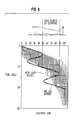
- Figure 8 illustrates a comparison of the effectiveness of an X-ray apparatus operated in accordance with the invention for acquiring images of a moving contrast bolus, as compared to a prior art technique having a stepped gantry.
- the vertical shading indicates the time and position data of the moving contrast bolus in one leg of a patient and the horizontal shading indicates the time and position data of the moving contrast bolus in the other leg of the patient.
- a stepped gantry having, for example, a program which acquires three images every 5 seconds and moves 20 cm closer to the toes each step of its longitudinal displacement, would completely miss acquiring images of the contrast bolus in both of the legs at the position corresponding to 60 cm. Furthermore, at the position corresponding to 80 cm, the contrast bolus will only be imaged in one leg and completely missed in the other leg. As clearly shown by the exposure points on the sweeping waveform, image data for the moving contrast bolus through both legs is acquired at each of the positions imaged by the stepped gantry technique.
Landscapes
- Engineering & Computer Science (AREA)
- Multimedia (AREA)
- Signal Processing (AREA)
- Apparatus For Radiation Diagnosis (AREA)
- Image Analysis (AREA)
- Radiography Using Non-Light Waves (AREA)
- Image Processing (AREA)
Applications Claiming Priority (2)
| Application Number | Priority Date | Filing Date | Title |
|---|---|---|---|
| US07/471,317 US4995064A (en) | 1990-01-29 | 1990-01-29 | Continuously sweeping multiple-pass image acquisition system for peripheral angiography |
| US471317 | 1990-01-29 |
Publications (3)
| Publication Number | Publication Date |
|---|---|
| EP0439711A2 true EP0439711A2 (de) | 1991-08-07 |
| EP0439711A3 EP0439711A3 (en) | 1991-09-04 |
| EP0439711B1 EP0439711B1 (de) | 1995-05-24 |
Family
ID=23871149
Family Applications (1)
| Application Number | Title | Priority Date | Filing Date |
|---|---|---|---|
| EP90122404A Expired - Lifetime EP0439711B1 (de) | 1990-01-29 | 1990-11-23 | Bilderfassungssystem mit kontinuierlicher Mehrfach-Abtastung für periphere Angiographie |
Country Status (4)
| Country | Link |
|---|---|
| US (1) | US4995064A (de) |
| EP (1) | EP0439711B1 (de) |
| JP (1) | JPH04212333A (de) |
| DE (1) | DE69019722T2 (de) |
Cited By (4)
| Publication number | Priority date | Publication date | Assignee | Title |
|---|---|---|---|---|
| DE4133018A1 (de) * | 1991-10-04 | 1993-04-08 | Manfred Dr Henne | Vorrichtung fuer die digitale subtraktionsangiografie |
| US9949704B2 (en) | 2012-05-14 | 2018-04-24 | Bayer Healthcare Llc | Systems and methods for determination of pharmaceutical fluid injection protocols based on x-ray tube voltage |
| US9950107B2 (en) | 2004-11-24 | 2018-04-24 | Bayer Healthcare Llc | Systems and methods for managing workflow for injection procedures |
| US10463782B2 (en) | 2006-12-29 | 2019-11-05 | Bayer Healthcare Llc | Patient-based parameter generation systems for medical injection procedures |
Families Citing this family (34)
| Publication number | Priority date | Publication date | Assignee | Title |
|---|---|---|---|---|
| JPH053867A (ja) * | 1991-06-28 | 1993-01-14 | Toshiba Corp | 三次元画像診断装置 |
| US5408521B1 (en) * | 1992-04-14 | 1997-08-26 | Xre Corp | Angiographic x-ray system wih 360 degree scanning |
| DE4220282A1 (de) * | 1992-06-20 | 1993-12-23 | Philips Patentverwaltung | Verfahren für die periphere Angiographie und Anordnung zur Durchführung des Verfahrens |
| US6397098B1 (en) * | 1994-09-21 | 2002-05-28 | Medrad, Inc. | Data communication and control for medical imaging systems |
| US5840026A (en) * | 1994-09-21 | 1998-11-24 | Medrad, Inc. | Patient specific dosing contrast delivery systems and methods |
| US6195450B1 (en) * | 1997-09-18 | 2001-02-27 | Siemens Corporate Research, Inc. | Methods and apparatus for controlling X-ray angiographic image acquisition |
| JP2000279400A (ja) * | 1999-03-30 | 2000-10-10 | Hitachi Medical Corp | パルスx線透視装置 |
| EP1812101A4 (de) * | 2004-11-16 | 2014-04-23 | Medrad Inc | Modellierung von pharmazeutischer verbreitung |
| DE102004059663A1 (de) * | 2004-12-10 | 2006-06-29 | Siemens Ag | Verfahren zur Bildgebung mit einem Mehrzeilen-Computertomographen |
| US7826884B2 (en) * | 2006-07-31 | 2010-11-02 | Siemens Medical Solutions Usa, Inc. | Live fluoroscopic roadmapping including targeted automatic pixel shift for misregistration correction |
| WO2008082937A2 (en) * | 2006-12-29 | 2008-07-10 | Medrad, Inc. | Modeling of pharmaceutical propagation |
| JP4938480B2 (ja) * | 2007-02-02 | 2012-05-23 | 富士フイルム株式会社 | 放射線撮像装置、放射線撮像方法、及びプログラム |
| JP4938481B2 (ja) * | 2007-02-02 | 2012-05-23 | 富士フイルム株式会社 | 放射線撮像装置、放射線撮像方法、及びプログラム |
| EP2170165B1 (de) | 2007-07-17 | 2018-12-05 | Bayer Healthcare LLC | Systeme zur bestimmung von parametern für ein verfahren zur schätzung der kardiopulmonalen funktion und zur flüssigkeitsabgabe |
| US8437519B2 (en) * | 2007-10-19 | 2013-05-07 | Siemens Medical Solutions Usa, Inc. | Automated image data subtraction system suitable for use in angiography |
| FR2924255A1 (fr) * | 2007-11-27 | 2009-05-29 | Gen Electric | Procede de traitement d'images cardiaques radiographiques en vue d'obtenir une image soustraite et recalee |
| US9421330B2 (en) * | 2008-11-03 | 2016-08-23 | Bayer Healthcare Llc | Mitigation of contrast-induced nephropathy |
| US8299413B2 (en) * | 2009-01-08 | 2012-10-30 | Siemens Aktiengesellschaft | Method for pixel shift calculation in digital subtraction angiography and X-ray diagnostic imaging system for generating images in digital subtraction angiography |
| CA2803169C (en) | 2010-06-24 | 2020-09-22 | Medrad, Inc. | Modeling of pharmaceutical propagation and parameter generation for injection protocols |
| US20140150523A1 (en) * | 2012-12-04 | 2014-06-05 | Halliburton Energy Services, Inc. | Calibration of a well acoustic sensing system |
| US9555379B2 (en) | 2013-03-13 | 2017-01-31 | Bayer Healthcare Llc | Fluid path set with turbulent mixing chamber, backflow compensator |
| US9526468B2 (en) * | 2014-09-09 | 2016-12-27 | General Electric Company | Multiple frame acquisition for exposure control in X-ray medical imagers |
| JP6662390B2 (ja) * | 2015-12-18 | 2020-03-11 | 株式会社島津製作所 | X線撮影装置 |
| EP3423130B1 (de) | 2016-03-03 | 2025-05-14 | Bayer Healthcare LLC | System und verfahren zur verbesserten fluidabgabe in injektorsystem für mehrere fluide |
| EP3538182A1 (de) | 2016-11-14 | 2019-09-18 | Bayer Healthcare LLC | Verfahren und systeme zur verifizierung des inhalts einer zur abgabe einer medizinischen flüssigkeit verwendeten spritze |
| JP2020150964A (ja) * | 2017-07-19 | 2020-09-24 | 株式会社島津製作所 | X線撮影装置 |
| AU2018323442B2 (en) | 2017-08-31 | 2024-06-27 | Bayer Healthcare Llc | Fluid path impedance assessment for improving fluid delivery performance |
| AU2018326485B2 (en) | 2017-08-31 | 2024-01-04 | Bayer Healthcare Llc | Injector pressure calibration system and method |
| CN110891630B (zh) | 2017-08-31 | 2022-04-26 | 拜耳医药保健有限公司 | 驱动构件定位和流体注入器系统机械校准的系统和方法 |
| JP7493337B2 (ja) | 2017-08-31 | 2024-05-31 | バイエル・ヘルスケア・エルエルシー | 流体インジェクタシステムにおける動的圧力制御のための方法 |
| CN110809482B (zh) | 2017-08-31 | 2023-03-07 | 拜耳医药保健有限公司 | 流体注入器系统体积补偿系统和方法 |
| CA3097557A1 (en) | 2018-04-19 | 2019-10-24 | Bayer Healthcare Llc | System and method for air detection in fluid injector |
| JP2021536278A (ja) | 2018-08-28 | 2021-12-27 | バイエル・ヘルスケア・エルエルシーBayer HealthCare LLC | 比性能を改善した流体注入器システム |
| CA3110859A1 (en) | 2018-08-28 | 2020-03-05 | Bayer Healthcare Llc | Fluid injector system, method of preventing fluid backflow, and computer program product |
Family Cites Families (11)
| Publication number | Priority date | Publication date | Assignee | Title |
|---|---|---|---|---|
| US4204225A (en) * | 1978-05-16 | 1980-05-20 | Wisconsin Alumni Research Foundation | Real-time digital X-ray subtraction imaging |
| US4450478A (en) * | 1981-09-09 | 1984-05-22 | Georgetown University | Digital fluorographic method and system |
| DE3203594A1 (de) * | 1982-02-03 | 1983-08-11 | Siemens AG, 1000 Berlin und 8000 München | Roentgendiagnostikanlage fuer angiographische roentgenaufnahmen |
| NL8304397A (nl) * | 1983-12-22 | 1985-07-16 | Philips Nv | Roentgenonderzoekapparaat met beeldsubstractie. |
| FR2560037B1 (fr) * | 1984-02-28 | 1988-04-08 | Thomson Cgr | Procede de controle de positionnement d'un patient par rapport a une installation de radiologie, et installation pour la mise en oeuvre de ce procede |
| JPH0822025B2 (ja) * | 1985-02-25 | 1996-03-04 | 株式会社日立製作所 | 画像入力装置 |
| JPH0657208B2 (ja) * | 1985-12-27 | 1994-08-03 | 株式会社東芝 | デイジタル・フルオログラフイ−装置 |
| JPH0683397B2 (ja) * | 1987-07-31 | 1994-10-19 | 株式会社島津製作所 | Dsa装置 |
| US4841555A (en) * | 1987-08-03 | 1989-06-20 | University Of Chicago | Method and system for removing scatter and veiling glate and other artifacts in digital radiography |
| DE3826550C2 (de) * | 1987-08-07 | 1994-01-13 | Toshiba Kawasaki Kk | Einrichtung zum Darstellen von Röntgenbildern |
| US4878115A (en) * | 1987-09-25 | 1989-10-31 | University Of Kentucky Research Foundation | Dynamic coronary roadmapping |
-
1990
- 1990-01-29 US US07/471,317 patent/US4995064A/en not_active Expired - Fee Related
- 1990-11-23 EP EP90122404A patent/EP0439711B1/de not_active Expired - Lifetime
- 1990-11-23 DE DE69019722T patent/DE69019722T2/de not_active Expired - Fee Related
-
1991
- 1991-01-28 JP JP3027954A patent/JPH04212333A/ja not_active Withdrawn
Cited By (6)
| Publication number | Priority date | Publication date | Assignee | Title |
|---|---|---|---|---|
| DE4133018A1 (de) * | 1991-10-04 | 1993-04-08 | Manfred Dr Henne | Vorrichtung fuer die digitale subtraktionsangiografie |
| US9950107B2 (en) | 2004-11-24 | 2018-04-24 | Bayer Healthcare Llc | Systems and methods for managing workflow for injection procedures |
| US10166326B2 (en) | 2004-11-24 | 2019-01-01 | Bayer Healthcare Llc | Devices, systems and methods for determining parameters of one or more phases of an injection procedure |
| US10463782B2 (en) | 2006-12-29 | 2019-11-05 | Bayer Healthcare Llc | Patient-based parameter generation systems for medical injection procedures |
| US9949704B2 (en) | 2012-05-14 | 2018-04-24 | Bayer Healthcare Llc | Systems and methods for determination of pharmaceutical fluid injection protocols based on x-ray tube voltage |
| US11191501B2 (en) | 2012-05-14 | 2021-12-07 | Bayer Healthcare Llc | Systems and methods for determination of pharmaceutical fluid injection protocols based on x-ray tube voltage |
Also Published As
| Publication number | Publication date |
|---|---|
| EP0439711B1 (de) | 1995-05-24 |
| DE69019722D1 (de) | 1995-06-29 |
| DE69019722T2 (de) | 1995-11-16 |
| EP0439711A3 (en) | 1991-09-04 |
| US4995064A (en) | 1991-02-19 |
| JPH04212333A (ja) | 1992-08-03 |
Similar Documents
| Publication | Publication Date | Title |
|---|---|---|
| EP0439711B1 (de) | Bilderfassungssystem mit kontinuierlicher Mehrfach-Abtastung für periphere Angiographie | |
| JP3257630B2 (ja) | 冠状動脈を形状特定する表示装置 | |
| EP0146991B1 (de) | Röntgenanlage mit Bildsubtraktion | |
| EP0655713B1 (de) | Computertomograph | |
| US5123056A (en) | Whole-leg x-ray image processing and display techniques | |
| US4448200A (en) | System and method for dynamic background subtraction | |
| US5630414A (en) | X-ray diagnostics installation for subtraction angiography | |
| US5544215A (en) | Digital angiography system with automatically determined frame rates | |
| US7907217B2 (en) | Systems and methods of subtraction angiography utilizing motion prediction | |
| US5463668A (en) | X-ray diagnosis apparatus | |
| JP3695878B2 (ja) | X線診断装置 | |
| KR100280198B1 (ko) | Ct촬영이가능한x선촬영장치및방법 | |
| EP2562564A2 (de) | Röntgenbildgebungsgerät und -verfahren | |
| JP7247719B2 (ja) | 放射線透視撮影装置 | |
| JP4127609B2 (ja) | X線診断装置 | |
| JPH08238232A (ja) | X線撮影装置 | |
| JPH06237924A (ja) | X線診断装置 | |
| JP4772355B2 (ja) | X線診断装置 | |
| US5594771A (en) | Digital angiographic apparatus | |
| JP4504034B2 (ja) | X線診断装置 | |
| Wilson et al. | Peripheral angiography digital image acquisition using rapid continuous sweeps of a moving gantry | |
| JPH0787397A (ja) | X線透視診断装置 | |
| JPS6137229A (ja) | D.s.a.装置 | |
| JPH0213184A (ja) | デジタルサブトラックション装置 | |
| EP0101746A1 (de) | System und Verfahren zur dynamischen Hintergrundsubtraktion |
Legal Events
| Date | Code | Title | Description |
|---|---|---|---|
| PUAI | Public reference made under article 153(3) epc to a published international application that has entered the european phase |
Free format text: ORIGINAL CODE: 0009012 |
|
| PUAL | Search report despatched |
Free format text: ORIGINAL CODE: 0009013 |
|
| 17P | Request for examination filed |
Effective date: 19901205 |
|
| AK | Designated contracting states |
Kind code of ref document: A2 Designated state(s): DE FR GB |
|
| AK | Designated contracting states |
Kind code of ref document: A3 Designated state(s): DE FR GB |
|
| 17Q | First examination report despatched |
Effective date: 19930804 |
|
| GRAA | (expected) grant |
Free format text: ORIGINAL CODE: 0009210 |
|
| AK | Designated contracting states |
Kind code of ref document: B1 Designated state(s): DE FR GB |
|
| PG25 | Lapsed in a contracting state [announced via postgrant information from national office to epo] |
Ref country code: FR Effective date: 19950524 |
|
| REF | Corresponds to: |
Ref document number: 69019722 Country of ref document: DE Date of ref document: 19950629 |
|
| EN | Fr: translation not filed | ||
| PLBE | No opposition filed within time limit |
Free format text: ORIGINAL CODE: 0009261 |
|
| STAA | Information on the status of an ep patent application or granted ep patent |
Free format text: STATUS: NO OPPOSITION FILED WITHIN TIME LIMIT |
|
| 26N | No opposition filed | ||
| PGFP | Annual fee paid to national office [announced via postgrant information from national office to epo] |
Ref country code: GB Payment date: 19961025 Year of fee payment: 7 |
|
| PGFP | Annual fee paid to national office [announced via postgrant information from national office to epo] |
Ref country code: DE Payment date: 19970121 Year of fee payment: 7 |
|
| PG25 | Lapsed in a contracting state [announced via postgrant information from national office to epo] |
Ref country code: GB Free format text: LAPSE BECAUSE OF NON-PAYMENT OF DUE FEES Effective date: 19971123 |
|
| GBPC | Gb: european patent ceased through non-payment of renewal fee |
Effective date: 19971123 |
|
| PG25 | Lapsed in a contracting state [announced via postgrant information from national office to epo] |
Ref country code: DE Free format text: LAPSE BECAUSE OF NON-PAYMENT OF DUE FEES Effective date: 19980801 |