EP0441099B1 - Griffe porteuse pour métiers à tisser à griffes - Google Patents
Griffe porteuse pour métiers à tisser à griffes Download PDFInfo
- Publication number
- EP0441099B1 EP0441099B1 EP90810955A EP90810955A EP0441099B1 EP 0441099 B1 EP0441099 B1 EP 0441099B1 EP 90810955 A EP90810955 A EP 90810955A EP 90810955 A EP90810955 A EP 90810955A EP 0441099 B1 EP0441099 B1 EP 0441099B1
- Authority
- EP
- European Patent Office
- Prior art keywords
- gripper
- yarn
- giver
- thread
- guide
- Prior art date
- Legal status (The legal status is an assumption and is not a legal conclusion. Google has not performed a legal analysis and makes no representation as to the accuracy of the status listed.)
- Expired - Lifetime
Links
Images
Classifications
-
- D—TEXTILES; PAPER
- D03—WEAVING
- D03D—WOVEN FABRICS; METHODS OF WEAVING; LOOMS
- D03D47/00—Looms in which bulk supply of weft does not pass through shed, e.g. shuttleless looms, gripper shuttle looms, dummy shuttle looms
- D03D47/12—Looms in which bulk supply of weft does not pass through shed, e.g. shuttleless looms, gripper shuttle looms, dummy shuttle looms wherein single picks of weft thread are inserted, i.e. with shedding between each pick
- D03D47/20—Constructional features of the thread-engaging device on the inserters
- D03D47/23—Thread grippers
- D03D47/233—Carrying grippers
Definitions
- the invention relates to a rapier gripper for rapier weaving machines, with a head part fastened to a flexible entry belt, and a belt rapier weaving machine with such a rapier.
- the rapier gripper In rapier weaving machines, the rapier gripper carries the weft thread with its head part, which has a suitable thread guide and a thread clamp, into the central area of the shed, where it is taken over by the slave gripper.
- the tasks of the bringer gripper to grasp the thread safely, not to lose it and to feed it precisely to the slave gripper require a fairly robust and therefore massive construction.
- the gripper slides on runners that are located at the lower ends of the two side walls. These runners put a heavy load on the warp threads, which can damage them.
- the side walls of the bringer gripper head are connected by a bridge-like top. The focus of this construction is high. Since the flexible belt, which moves the head part through the shed, runs directly over the warp threads, the high center of gravity results in a torque that is one movement which is difficult to control and tends to lift off the head part.
- a bringer gripper is known, the head part of which comprises a one-piece base body which likewise has two runners as a sliding surface.
- This bringer gripper also has the other features mentioned in the preamble of claim 1.
- the advantage of the invention can be seen in the fact that the center of gravity of the gripper head is low and that this enables a movement of the gripper that is less prone to lifting off. Thanks to the wide sliding surface of the hook head, which is flat or convex, the warp threads are protected. In addition, the open gripper head allows good insight for control purposes and good accessibility, especially to the thread clamp, which is advantageous in terms of cleaning and repair options.
- the bringer gripper head according to the invention has a one-piece base body that can be manufactured inexpensively from sheet metal.
- the thread clamp is attached to this body.
- the thread guide which is arranged on the upper edge of the reed-side gripper wall, can be produced, for example, simply by bending the sheet metal from which the base body is made.
- the thread guide can also be produced by means of an indentation broken out of the hook wall.
- the base body of the bringer gripper head according to the invention is shaped like a sheath, so that the slave gripper can penetrate into its interior and take over the weft thread presented there.
- the thread clamp is arranged in the interior so that there is still free space for the slave gripper. it is located immediately next to the goods-side gripper wall. With a rigid, fin-shaped lamella attached to the clamp, the weft thread coming from the high-lying thread guide is deflected against the bottom of the hook head before the thread is then guided upwards again to the clamping point.
- the thread deflection fin of the clamp results in a thread guide in the hook head, which runs diagonally through the free interior for the slave hook.
- the thread clamp which is essentially already known apart from the thread deflection fin (DE-PS 29.47.399), holds the weft thread with its clamping point in the horizontal direction. Thanks to this, the thread end protrudes from the hook through a trough in the side wall and therefore does not come into contact with the warp threads, which rules out mutual interference between the weft thread and the warp thread.
- the clamping point provided in the bringer gripper according to the invention and the associated trough in the side wall make it possible to remove fibers stuck on the side by means of a suction nozzle, which is advantageous compared to cleaning with a suction nozzle below the gripper guideway.
- the invention also relates to a belt rapier weaving machine in which the entry belts of the rapiers are moved back and forth by means of oscillating belt wheels.
- the Bring gripper according to the invention is provided for weaving machines in which the weft thread is presented horizontally.
- the horizontal weft template in contrast to the vertical weft template, which is available on other rapier weaving machines, requires a rapier gripper for which there is a risk of warp threads being torn. This danger does not exist in the case of the grabber according to the invention.
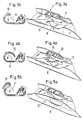
- FIGS. 5a and 5b show two further variants of the gripper head according to the invention, corresponding to FIGS. 3a and 3b.
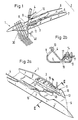
- the gripper head 1 shown in FIG. 1 is shown without being attached to the flexible entry belt with which it is pushed into the shed 30.
- the base body 2 which essentially has a U-shaped cross-sectional profile, there is the thread clamp 3 on the goods side.
- the weft thread 4 that is taken from a fixed thread supply (not shown) just enters the thread clamp 3 in FIG .
- a cutting device is actuated, which is indicated symbolically by the scissors 40.
- the free cut end which has now become the tip of the weft thread 4, then protrudes laterally out of the hook head 1 through the trough 11 in the side wall 7.
- the base body 2 consists of the base 5, which is designed as a sliding surface, and the two side walls 6 and 7.
- the gripper wall 6 on the reed side has a contour of the upper edge toward the hook tip, which contour with respect to the feed of the weft thread 4 to the thread clamp 3 is suitably shaped: After the rising curve, which lies immediately behind the hook tip, the upper edge sinks into a trough 8. Following the trough 8 is followed by a rising slope 9 towards the middle of the hook. By means of this rising slope 9, the thread 4 is inserted into the Thread clamp 3 introduced. The rapier head 1 pushed further into the shed then forces the thread 4 into the trough-shaped thread guide 10.
- the thread guide 10 and the thread clamp 3 can be seen more clearly in FIG. 2a.
- the base 12 of the terminal 3 the is welded onto the base body 2, for example, the elastic tongue 13 and the rigid clamping jaw 15 are fastened by means of screws.
- the tongue 13 and the jaw 15 together form a funnel-shaped jaw 16.
- the jaw 15 is provided with an opening for a cam 14.
- This cam 14 is fastened on the tongue 13 and is used to open the clamping gap in the retracted state of the gripper, in order to be able to suck off stuck fibers with a suction nozzle, which is then located at the side trough 11.
- the opening 18 in the bottom 5 next to the thread clamp 3 is provided for thick yarn.
- the cross-section in FIG. 2b runs through the two lateral troughs 8 and 11.
- the gripper head base 5 has a sliding surface which is flat in the middle region except for the opening 18 and is convexly curved in the edge regions. If a rounded lower edge is provided at the opening 18, the warp threads are no longer damaged by the sliding surface.
- the thread 4 runs diagonally from the thread guide 10 to the opening 18 through the free interior of the hook head. This is made possible by the thread deflection fin 17, which together with the clamping jaw 15 form the upper part of the thread clamp 3.
- the tongue 13 with the cam 14 is not cut and is shown in a frontal view. It can be seen that the tip of the tongue is curved downwards.
- the variants of the gripper head shown in FIGS. 3a to 5a differ from the exemplary embodiment described above only in the design of the gripper wall on the reed side.
- the wall piece is behind the trough 8 - in the first exemplary embodiment bent outwards to form a channel - is now bent against the center of the hook and provided with an indentation 19 which serves as a thread guide.
- the weft thread is only partially indicated by its position 4 '.
- the thread guide 19 is also designed as an indentation.
- the wall piece projecting towards the center of the hook is here extended to a partial roofing 20 of the space between thread guide 19 and clamp 3.
- the front edge of this canopy 20 helps with the correct feeding of the weft thread into the jaw 16.
- the thread guide is again channel-like as in the first embodiment.
- the outwardly curved wall piece 21 is extended. It serves to displace the upper warp thread sheet upwards and thereby protect it from damage caused by protruding parts of the hook head.
- a similar roof is available on the reed side of the gripper of the CH-PS 592.761. The elimination of such a canopy in the gripper heads according to the invention described above has the advantage that the gripper requires a little less space and thus makes it possible to reduce the front compartment cross section.
Landscapes
- Engineering & Computer Science (AREA)
- Textile Engineering (AREA)
- Looms (AREA)
Claims (9)
- Griffe porteuse pour métier à tisser à projectile, comportant une pièce de tête (1) fixée sur une bande d'introduction souple et qui çomporte un corps de base (2) en une seule pièce qui pour sa plus grande partie est ouvert vers le haut et sur lequel est fixé un pince-fil (3) et un guide supérieur (10) pour le fil de trame (4), le guide et la pince étant disposés soit du côté du peigne soit du côté du tissu, de sorte qu'ils présentent le fil diagonalement et tendu à travers un espace intérieur libre de la pièce de tête à la griffe de reprise, caractérisée en ce que la pièce de tête (1) est réalisée à partir d'une pièce de tôle mise en forme, dont une partie forme une paroi de fond (5) qui est prévue comme surface de glissement.
- Griffe porteuse selon la revendication 1, caractérisée en ce que la pièce de tête (1) présente un guide-fil (10) en forme de canal, créé par le cintrage d'une tôle.
- Griffe porteuse selon la revendication 1, caractérisée en ce que la pièce de tête (1) présente comme guide-fil une découpe (19) réalisée dans la paroi (6) de la griffe.
- Griffe porteuse selon l'une des revendications 1 ou 3, caractérisée en ce qu'il existe un recouvrement partiel (20) de l'espace situé entre le guide-fil (10) et la pince (3).
- Griffe porteuse selon l'une des revendications 1 à 3, caractérisée en ce qu'il existe un recouvrement partiel (21) de la paroi de la pièce de tête qui est située du côté du peigne.
- Griffe porteuse selon l'une des revendications 1 à 5, caractérisée en ce que le pince-fil (3) présente une ailette (17) de déviation du fil qui retient le fil vers le bas entre le guide (10) et l'emplacement de pinçage.
- Griffe porteuse selon la revendication 6, caractérisée en ce que la surface de glissement (5) présente une découpe (18) en dessous de l'ailette (17) de déviation du fil.
- Griffe porteuse selon l'une des revendications 1 à 7, caractérisée en ce que la pince (3) maintient le fil (4) au moins approximativement horizontal à son extrémité.
- Métier à tisser à projectile et à présentation horizontale de la duite, et comportant une griffe porteuse selon l'une des revendications 1 à 8.
Applications Claiming Priority (2)
| Application Number | Priority Date | Filing Date | Title |
|---|---|---|---|
| CH35390 | 1990-02-05 | ||
| CH353/90 | 1990-02-05 |
Publications (2)
| Publication Number | Publication Date |
|---|---|
| EP0441099A1 EP0441099A1 (fr) | 1991-08-14 |
| EP0441099B1 true EP0441099B1 (fr) | 1996-01-31 |
Family
ID=4185093
Family Applications (1)
| Application Number | Title | Priority Date | Filing Date |
|---|---|---|---|
| EP90810955A Expired - Lifetime EP0441099B1 (fr) | 1990-02-05 | 1990-12-06 | Griffe porteuse pour métiers à tisser à griffes |
Country Status (4)
| Country | Link |
|---|---|
| US (1) | US5129431A (fr) |
| EP (1) | EP0441099B1 (fr) |
| JP (1) | JPH04214439A (fr) |
| DE (1) | DE59010104D1 (fr) |
Families Citing this family (13)
| Publication number | Priority date | Publication date | Assignee | Title |
|---|---|---|---|---|
| IT1255629B (it) * | 1992-05-22 | 1995-11-09 | Luciano Corain | Pinza di trazione perfezionata per telaio tessile |
| IT231509Y1 (it) * | 1993-10-27 | 1999-08-03 | Interpatents Ltd | Pinza portante per macchine per tessitura. |
| IT1274589B (it) * | 1994-08-05 | 1997-07-18 | Nuovo Pignone Spa | Sistema perfezionato di presa e serraggio della trama nella pinza di trazione di un telaio tessile |
| WO1997047792A1 (fr) * | 1996-06-07 | 1997-12-18 | Picanol N.V. | Pince de transfert pour une machine a tisser a rapieres |
| BE1010334A3 (nl) * | 1996-06-07 | 1998-06-02 | Picanol Nv | Inrichting voor het inbrengen van een inslagdraad bij een grijperweefmachine. |
| DE59604891D1 (de) * | 1996-06-07 | 2000-05-11 | Sulzer Textil Ag Rueti | Fadenklemme für einen Bringergreifer und Bringergreifer mit Fadenklemme |
| DE59606723D1 (de) * | 1996-06-14 | 2001-05-10 | Rueti Ag Maschf | Tragkörper für eine Fadenklemme und Bringergreifer für eine Greiferwebmaschine, mit Tragkörper |
| JPH1136159A (ja) * | 1997-07-11 | 1999-02-09 | Toyota Autom Loom Works Ltd | レピア織機における緯入れ装置 |
| BE1011604A3 (nl) * | 1997-12-11 | 1999-11-09 | Picanol Nv | Grijperlichaam voor een grijper voor een weefmachine. |
| DE10018939A1 (de) * | 2000-04-17 | 2001-10-18 | Picanol Nv | Greifergehäuse für einen Greifer einer Webmaschine |
| EP1806443B1 (fr) * | 2006-01-06 | 2009-02-11 | Sultex AG | Pince d'amenée pour métier à tisser à pince |
| WO2010142264A1 (fr) | 2009-06-10 | 2010-12-16 | Lindauer Dornier Gesellschaft Mbh | Dispositif et procédé d'insertion des fils de trame dans une machine à tisser à pinces |
| CN105088495A (zh) * | 2015-09-22 | 2015-11-25 | 重庆群禾纺织有限公司 | 一种用于剑杆织机上的送纬剑机构 |
Family Cites Families (9)
| Publication number | Priority date | Publication date | Assignee | Title |
|---|---|---|---|---|
| CH514707A (de) * | 1970-10-27 | 1971-10-31 | Fischer Ag Brugg Georg | Vorrichtung zum Absaugen von Faserresten und Staubteilchen an Schussfadeneintragsorganen an Webmaschinen |
| US3842867A (en) * | 1973-03-22 | 1974-10-22 | Rockwell International Corp | Weft inserting carrier |
| DE2752667A1 (de) * | 1977-11-25 | 1979-05-31 | Hagemann B & Co | Schussfaden-eintragvorrichtung fuer schuetzenlose webmaschinen |
| CH635624A5 (de) * | 1979-02-05 | 1983-04-15 | Saurer Ag Adolph | Vorrichtung an schuetzenloser webmaschine zur uebergabe der schussfadenspitze. |
| JPS5922128Y2 (ja) * | 1979-07-10 | 1984-07-02 | 株式会社豊田自動織機製作所 | 無杼織機における緯入れ装置 |
| IT1132844B (it) * | 1980-09-15 | 1986-07-09 | Nuovo Pignone Spa | Perfezionamenti nelle pinze passatrama per telai tessili |
| US4757844A (en) * | 1987-05-05 | 1988-07-19 | Vamatex S.P.A. | Weft grippers for shuttleless weaving looms |
| JPH01245336A (ja) * | 1988-03-28 | 1989-09-29 | Fujitsu Ltd | 外部共有バスの割込み制御方式 |
| IT1226865B (it) * | 1988-08-19 | 1991-02-20 | Nuovo Pignone Spa | Perfezionamenti in una pinza passatrama di condotta per telai tessili senza navetta. |
-
1990
- 1990-12-06 EP EP90810955A patent/EP0441099B1/fr not_active Expired - Lifetime
- 1990-12-06 DE DE59010104T patent/DE59010104D1/de not_active Expired - Fee Related
-
1991
- 1991-01-28 US US07/646,671 patent/US5129431A/en not_active Expired - Fee Related
- 1991-02-04 JP JP3013446A patent/JPH04214439A/ja active Pending
Also Published As
| Publication number | Publication date |
|---|---|
| US5129431A (en) | 1992-07-14 |
| JPH04214439A (ja) | 1992-08-05 |
| EP0441099A1 (fr) | 1991-08-14 |
| DE59010104D1 (de) | 1996-03-14 |
Similar Documents
| Publication | Publication Date | Title |
|---|---|---|
| EP0441099B1 (fr) | Griffe porteuse pour métiers à tisser à griffes | |
| DD269408A5 (de) | Fuehrungsmittel zur bewegung eines mit greifern versehenen schusspaares innerhalb des webfaches eines webstuhles | |
| CH635625A5 (de) | Schuetzenlose webmaschine zur herstellung von geweben mit musterungsrapport. | |
| EP0146663B1 (fr) | Organe d'insertion du fil de trame pour machines à tisser à griffes | |
| DE1535556C3 (de) | Schußeintragvorrichtung für Webmaschinen mit kontinuierlicher SchuBzuführung | |
| DE68916602T2 (de) | Vorrichtung zur Steuerung der Bewegung der Schusseintragsgreifer im Fach von schützenlosen Webmaschinen. | |
| DE102010034969B3 (de) | Webblatt und Webmaschine zur Webmusterbildung bei Geweben mit Zusatzmustereffekten | |
| DE3812960A1 (de) | Greiferwebmaschine | |
| EP0906461B1 (fr) | Pince de transfert pour une machine a tisser a rapieres | |
| DE10334359B3 (de) | Webmaschine zum Herstellen eines Gewebes in Leinwand- und Dreherbindung | |
| DE3926637A1 (de) | Schussfadeneintragsgreiferstange fuer einen schuetzenlosen webstuhl | |
| DE69703711T2 (de) | Bringergreifer für eine Greiferwebmaschine | |
| DE2643627C2 (de) | Bringergreifer für Webmaschinen mit Entnahme des Schußfadens von ortsfesten Spulen | |
| CH660043A5 (de) | Vorrichtung an einer schuetzenlosen webmaschine zum bilden einer gewebekante. | |
| EP0576854A1 (fr) | Métier à tisser à griffes | |
| DE69514998T2 (de) | Vorrichtung zum Führen der Bewegung eines Greiferpaares durch das Fach von Webmaschinen | |
| CH625573A5 (en) | Taker gripper for weaving machines with extraction of the weft thread from fixed bobbins | |
| DE2642809A1 (de) | Nehmergreifer fuer webmaschinen mit entnahme des schussfadens von ortsfesten spulen | |
| DE2622397A1 (de) | Schussfaden-nehmertraeger fuer webmaschinen | |
| DE69211392T2 (de) | Mitnehmergreifer für schützenlose Webmaschinen, insbesondere zum Weben von synthetischen Fäden | |
| DE553886C (de) | Schussfadenzubringervorrichtung fuer Webstuehle mit Greiferwebschuetzen | |
| DE69518113T2 (de) | Verbessertes Führungssystem für den Greifereintragsband in eine schützenlose Webmaschine | |
| DE2330117A1 (de) | Schuetzenloser webstuhl mit einer schussfadengreiferfuehrung | |
| CH668092A5 (de) | Fadensteuerung fuer naehmaschinen. | |
| EP0811712B1 (fr) | Pince-fil pour griffe d'amenée et griffe d'amenée avec un tel pince-fil |
Legal Events
| Date | Code | Title | Description |
|---|---|---|---|
| PUAI | Public reference made under article 153(3) epc to a published international application that has entered the european phase |
Free format text: ORIGINAL CODE: 0009012 |
|
| AK | Designated contracting states |
Kind code of ref document: A1 Designated state(s): BE DE FR IT |
|
| 17P | Request for examination filed |
Effective date: 19901210 |
|
| 17Q | First examination report despatched |
Effective date: 19940517 |
|
| RAP1 | Party data changed (applicant data changed or rights of an application transferred) |
Owner name: SULZER RUETI AG |
|
| GRAA | (expected) grant |
Free format text: ORIGINAL CODE: 0009210 |
|
| AK | Designated contracting states |
Kind code of ref document: B1 Designated state(s): BE DE FR IT |
|
| PG25 | Lapsed in a contracting state [announced via postgrant information from national office to epo] |
Ref country code: FR Effective date: 19960131 |
|
| REF | Corresponds to: |
Ref document number: 59010104 Country of ref document: DE Date of ref document: 19960314 |
|
| ITF | It: translation for a ep patent filed | ||
| EN | Fr: translation not filed | ||
| PLBE | No opposition filed within time limit |
Free format text: ORIGINAL CODE: 0009261 |
|
| STAA | Information on the status of an ep patent application or granted ep patent |
Free format text: STATUS: NO OPPOSITION FILED WITHIN TIME LIMIT |
|
| 26N | No opposition filed | ||
| PG25 | Lapsed in a contracting state [announced via postgrant information from national office to epo] |
Ref country code: DE Effective date: 19970902 |
|
| PGFP | Annual fee paid to national office [announced via postgrant information from national office to epo] |
Ref country code: BE Payment date: 20001130 Year of fee payment: 11 |
|
| PG25 | Lapsed in a contracting state [announced via postgrant information from national office to epo] |
Ref country code: BE Free format text: LAPSE BECAUSE OF NON-PAYMENT OF DUE FEES Effective date: 20011231 |
|
| BERE | Be: lapsed |
Owner name: SULZER RUTI A.G. Effective date: 20011231 |
|
| PG25 | Lapsed in a contracting state [announced via postgrant information from national office to epo] |
Ref country code: IT Free format text: LAPSE BECAUSE OF NON-PAYMENT OF DUE FEES;WARNING: LAPSES OF ITALIAN PATENTS WITH EFFECTIVE DATE BEFORE 2007 MAY HAVE OCCURRED AT ANY TIME BEFORE 2007. THE CORRECT EFFECTIVE DATE MAY BE DIFFERENT FROM THE ONE RECORDED. Effective date: 20051206 |