EP0906461B1 - Pince de transfert pour une machine a tisser a rapieres - Google Patents
Pince de transfert pour une machine a tisser a rapieres Download PDFInfo
- Publication number
- EP0906461B1 EP0906461B1 EP97928158A EP97928158A EP0906461B1 EP 0906461 B1 EP0906461 B1 EP 0906461B1 EP 97928158 A EP97928158 A EP 97928158A EP 97928158 A EP97928158 A EP 97928158A EP 0906461 B1 EP0906461 B1 EP 0906461B1
- Authority
- EP
- European Patent Office
- Prior art keywords
- carrying gripper
- accordance
- gripper means
- positioning
- gripper
- Prior art date
- Legal status (The legal status is an assumption and is not a legal conclusion. Google has not performed a legal analysis and makes no representation as to the accuracy of the status listed.)
- Expired - Lifetime
Links
- 239000004744 fabric Substances 0.000 claims description 16
- 238000009941 weaving Methods 0.000 claims description 8
- 210000002414 leg Anatomy 0.000 description 22
- 235000014676 Phragmites communis Nutrition 0.000 description 3
- 210000000689 upper leg Anatomy 0.000 description 3
- 238000013459 approach Methods 0.000 description 2
- 229910052782 aluminium Inorganic materials 0.000 description 1
- XAGFODPZIPBFFR-UHFFFAOYSA-N aluminium Chemical compound [Al] XAGFODPZIPBFFR-UHFFFAOYSA-N 0.000 description 1
- 230000009286 beneficial effect Effects 0.000 description 1
- 230000015572 biosynthetic process Effects 0.000 description 1
- 239000003795 chemical substances by application Substances 0.000 description 1
- 239000011248 coating agent Substances 0.000 description 1
- 238000000576 coating method Methods 0.000 description 1
- 238000001514 detection method Methods 0.000 description 1
- 239000011810 insulating material Substances 0.000 description 1
- 239000000463 material Substances 0.000 description 1
- 229910052751 metal Inorganic materials 0.000 description 1
- 239000002184 metal Substances 0.000 description 1
- 229910001220 stainless steel Inorganic materials 0.000 description 1
- 239000010935 stainless steel Substances 0.000 description 1
- 230000008719 thickening Effects 0.000 description 1
Images


Classifications
-
- D—TEXTILES; PAPER
- D03—WEAVING
- D03D—WOVEN FABRICS; METHODS OF WEAVING; LOOMS
- D03D47/00—Looms in which bulk supply of weft does not pass through shed, e.g. shuttleless looms, gripper shuttle looms, dummy shuttle looms
- D03D47/12—Looms in which bulk supply of weft does not pass through shed, e.g. shuttleless looms, gripper shuttle looms, dummy shuttle looms wherein single picks of weft thread are inserted, i.e. with shedding between each pick
- D03D47/20—Constructional features of the thread-engaging device on the inserters
- D03D47/23—Thread grippers
- D03D47/233—Carrying grippers
-
- D—TEXTILES; PAPER
- D03—WEAVING
- D03D—WOVEN FABRICS; METHODS OF WEAVING; LOOMS
- D03D47/00—Looms in which bulk supply of weft does not pass through shed, e.g. shuttleless looms, gripper shuttle looms, dummy shuttle looms
- D03D47/12—Looms in which bulk supply of weft does not pass through shed, e.g. shuttleless looms, gripper shuttle looms, dummy shuttle looms wherein single picks of weft thread are inserted, i.e. with shedding between each pick
- D03D47/20—Constructional features of the thread-engaging device on the inserters
Definitions
- the invention relates to a sensor rapier for a rapier weaving machine, with means for picking up and positioning a weft thread is provided on a deflecting guide is kept on hand.
- a weft thread is usually used Help from a donor gripper and a slave gripper Loom passed through.
- the encoder gripper takes on the entry side of the shed on a weft, which means a thread feeder is kept ready. If the encoder gripper is inserted into the shed, the weft picked up, positioned within the encoder gripper and clamped by means of a clamp. Approximately in the middle of the shed the weft thread is taken over by a slave gripper, clamped by a clamp of the slave gripper and by that Take gripper to the other side of the shed. The The encoder gripper moves back in empty during this time its starting position in front of the entry page of the shed.
- the invention has for its object a donor gripper of the type mentioned in such a way that a ready Weft is taken safely, however, the danger gripping a warp thread is significantly reduced.
- the encoder gripper according to the invention can have one ready Grip the weft well because of the deflection guide of a possible running direction of a warp thread clearly has different course, record safely. On the other hand the risk is relatively small that the encoder gripper catches incorrectly running warp thread. Furthermore there are no dimensional restrictions of a weft thread to be picked up.
- the means for picking up a weft thread in different walls the hollow chamber are arranged. This ensures that the Tension of the weft thread when carried by the donor gripper is gradually increased so that the risk of weft breaks is limited.
- the means for positioning in two different walls of the Hollow chamber are arranged and face each other at a distance. This ensures that the encoder gripper a Holds piece of the weft freely in its hollow chamber, so that it very well from a slave gripper or even from a slave hook can be taken over.
- the means for receiving and / or the means for positioning in the direction of movement of the gripper with respect to the position the weft thread held ready to each other are. This ensures that the tension of the weft thread gradually increased when carried by the encoder gripper is, so that the risk of weft breakage is further limited is.
- the agent to position the the edge of the goods to be woven Tissue is assigned as a means of picking up one after is assigned to the inside protruding tab in the encoder gripper a guide surface leading to the positioning means forms.
- the facing the fabric edge of a fabric to be woven The gripper side is more vulnerable regarding an unwanted picking up of a warp thread. Because the means to pick up, namely the tab protrudes into the encoder gripper, there is a possible contact of this tab with a Warp thread largely excluded.
- a thread clamp is accommodated in the encoder gripper regarding the means for positioning on the edge of the goods facing side is arranged.
- the encoder gripper from a substantially U-shaped plate is formed, - in the direction of movement of the encoder gripper seen - a leg located above the deflection guide and one on the side next to the deflection guide Owns thigh. It is advantageous if the funds to pick up - seen in the direction of movement of the gripper - on opposite sides of the deflection guide are located.
- the encoder gripper is provided with a sliding surface
- the guide means is assigned in which a holder for the encoder gripper and / or are guided for a gripper belt.
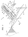
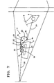
- the device 1 shown in Fig. 1 for entering a Weft thread 2 for a rapier weaving machine contains a donor rapier 3 and a deflection guide 4.
- the one to be fed Weft thread 2 extends from the edge of a fabric 8 through a thread guide eyelet 6 of a thread feeder 5 to a weft supply, not shown.
- the Weft 2 runs in the direction of B from the weft supply the thread feeder 5.
- the deflection guide 4 is in the illustrated embodiment Part of a guide profile 9, which is a gripper belt 17 leads, on which a holder 16 is attached which the encoder gripper 3 is mounted (Fig. 4). Furthermore 1 are warp threads 10, 11 of a warp thread family and Shed formation means 12, 13 indicated that a shed 14 form the warp threads 10, 11. For the sake of clarity a sley with a reed not shown, which itself is located between the fabric 8 and the shedding means 12, 13.
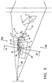
- FIG. 2 shows the position of the encoder gripper to the deflection guide 4.
- the weft thread 2 runs from the thread guide eyelet 6 over the deflection edge 7 of the deflection guide 4 to the Goods edge of the fabric 8 with which the previously fed Weft connected after striking with the help of the reed remains.
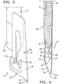
- Fig. 1 to 5 there is the encoder gripper 3 essentially from a curved plate 15, in particular from a stainless steel plate or aluminum plate, which means a holder 16 is connected to a gripper belt 17.
- the Plate 15 is bent into a U-shaped cross section so that it extends in the longitudinal direction of the master gripper 3 Hollow chamber 31 forms.
- This hollow chamber 31 is at the front and rear end of the gripper 3 and to the deflection guide 4 open as can be seen from the further description still results.
- Fig. 1 has the U-shaped Plate 15 a long leg that over the deflection guide 4 is arranged, and a short leg that is to the side of the deflection guide 4.
- the donor gripper with means for picking up the weft thread 2, with means for positioning of the weft thread 2 within the donor gripper 3 and with Means to take away or pinch the picked weft equipped.
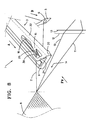
- the front end of the encoder gripper 3, the essentially only from the crossbar connecting the legs 32 is wedge-shaped to a point 20, as can be seen in particular from FIG. 4.
- the sloping one Bottom of the crosspiece 32 forms together with the at a distance to the beginning of 20 short legs one as Guide designed receptacle 18 for the weft.
- the weft 2 slides down on this receptacle 18 (FIG.
- a tab 25 is cut out and bent inwards, which forms a second means for receiving the weft thread 2.
- This tab 25 extends obliquely to the front and then forms an approximately wedge-shaped Tip 26 has a guide surface 21 which slants the weft up into the plane of the longer leg 24 to one recess 22 provided there leads as a second means is used for positioning.
- FIGS. 2 and 7 detects this serving as a means for receiving tab 25 the Section 2B of the weft thread, which is between the deflecting edge 7 and the edge of the fabric 8 is located.
- the of the Tip 26 of the tab 25 forms an edge 27 running downwards an oblique guide that is flush with a web 28 of the holder 16 connects, which is inclined to the foot part 29 of the holder 16 runs out, which is arranged in the extension of the gripper belt 17 is.
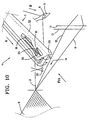
- the encoder gripper 3 contains a thread clamp 30, attached to the longer leg 24 of the plate 15 inside is.
- the thread clamp 30 is located at a point between the guide surface 21 of the tab 25 and the tissue 8 lies.
- the thread clamp 30 is in the embodiment from a leaf spring, which is in the direction of movement A of The gripper runs at the bottom of the plate 15 is attached inside.
- the thread clamp 30 acts on the inside the plate 15 together.
- the tab 25 as a means for picking up, guides the weft section 2B also the thread clamp 30.
- the encoder gripper 3 is such designed that its height starting from the top towards to the gripper belt 17 increases steadily so that there are none Places where warp threads 10, 11 can be detected.
- the tip 26 of the tab 25 projects into the Hollow chamber 31 into it, but only with a size that is less than half the height of the web is 32.
- the distance C according to FIG. 2 is between the inside of the longer leg 24 of the plate 15 and the deflection edge 7 of the deflection part 4 at least 2 mm, preferably between 3 and 5mm.
- the deflection edge protrudes 7 of the deflection guide 4 of the weft thread 2 in the the plate 15 formed hollow chamber 31 in such a way that the Means for picking up the weft thread 2, i.e. that of the Tip 20 of the web 32 outgoing guide 18 and the Tip 26 of the tab 25 outgoing guide 21 each on opposite Sides of the deflection edge 7 are. Since the Hollow chamber 31 is open at the front and back, the encoder gripper can 3 move freely along the deflection guide 4.
- the ready weft thread obliquely from the fabric edge of the fabric 8 to the thread feeder 5 via the deflection edge 7, i.e. obliquely to the direction of movement A of the encoder gripper 3 of the Tissue 8 away.
- the deflection edge 7 which in Direction of movement A must be correspondingly long.
- the weft 2 successively taken up by the guide surfaces 18 and 21 and also one after the other in the recesses 19 and 22 positioned and also inserted into the weft clamp 30 is a gradual increase in the voltage in the Weft so that the risk of weft breakage is reduced is.
- An increase in the tension of the weft thread 2 takes place if the weft 2 due to guiding along the Guide surfaces 18 and 21 and / or extended on the deflection edge becomes.
- FIGS. 1 to 11 Deviating from the embodiment of FIGS. 1 to 11 must of course the weft thread 2 is not between a thread feeder 5 and the tissue 8 are kept ready.
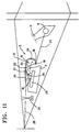
- FIG 12 shows an exemplary embodiment, in which a weft thread 2 by means of a thread guide 33 is provided, which is described in a US 4,840,203 disclosed manner on a weaving loom of a weaving machine is appropriate.
- the weft thread is in the area of the fabric 8 2 fed by means of a feed clamp 34, which via a Mechanism according to US 4,840,203 is moved.
- weft thread 2 is also such a deflection edge 7 guided a deflection guide 4 that he is already in the described manner in the region of the hollow chamber 31 of the Giver gripper 3 is located, so that it gradually increases Voltage can be picked up by the encoder gripper 3 when it moves in direction A towards the shed.
- the weft thread by means of the thread clamp 30 is not directly clamped to the underside of the plate 15. Rather is a Intermediate piece 36 made of metal provided by means of a or more elastic elements 37 attached to the plate 15 is.
- the elastic elements 37 are, for example made of a rubber-like elastic liner and insulating material.
- the deflection guide 4 with the deflection edge 7 not in one piece the guide profile 9, but rather as its own Component manufactured and by means of screws 42 or the like. to the Guide profile 9 is attached.
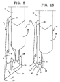
- a U-shaped plate 15 is provided, which one located above the deflection edge 7 of the deflection guide 4 long legs and one on the side next to the deflection guide has short legs located and a hollow chamber 31 forms, in which the deflection edge 7 of the deflection guide 4th protrudes such that the weft thread 2 on both sides of the deflection guide 4 is added.
- the web 32 of the U-shaped plate is shorter than the upper one Leg, so that the guide surface serving as a means for receiving 39 essentially at the upper edge of the web begins and then to one that serves as a means of positioning Recess 19 of the short leg runs.
- the upper Leg forms a tip 40 that faces inwards to the hollow chamber something is bent towards the detection of warp threads to avoid.
- One of the longer legs is on the inside Tab 25 bent, which forms a tip 26, one of which serving as a means for receiving the weft thread guide surface 21 leads to a recess 22 which as a means for Positioning the weft serves.
- the clamp also exists with this Embodiment from a leaf spring strip, which on the Attached inside the longer leg of the plate 15 is.
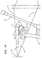
- the slopes 53 form a point directed to the stop line 51.
- the plane 50 runs in which the Guide surfaces 48 of the guide elements 43 lie somewhat below the stop edge 51, i.e. the edge of a fabric, against which the Webblatt 47 a registered Weft thread.
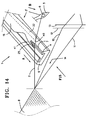
- the encoder gripper 3 of the embodiment 1 to 13 or the encoder gripper 3 'of FIGS. 14 to 16 is provided with a sliding surface 46 with which it is outside is guided on an outer surface 45 of the guide elements 43.
- the sliding surface 46 is a section of the short leg of the U-shaped plate that extends towards the shed towards the one used for positioning Recess 19 connects, for example in FIG. 5 and 16 can be seen.
- the approach 44 of the guide elements 43 protrudes into the hollow chamber 31 of the master gripper 3.
- the forms the sliding surface 46 with a slide bar or Coating is provided, which consists of a well lubricated, wear-resistant material.
- the Approaches 44 of the guide elements 43 none of the top of the Gripper belt 17 and the foot part 29 of the holder 16 assigned Guide surface 52.
Landscapes
- Engineering & Computer Science (AREA)
- Textile Engineering (AREA)
- Looms (AREA)
Claims (15)
- Griffe transmettrice (3, 3') pour une machine à tisser à griffes, qui est pourvue de moyens pour recevoir et positionner un fil de trame (2) qui, reposant sur un guidage de détour (4, 7) est tenu à disposition, caractérisée en ce que la griffe transmettrice (3, 3') forme une chambre creuse (31) s'étendant dans la direction longitudinale, ouverte à l'avant et à l'arrière ainsi qu'au côté orienté vers le guidage de détour (4, 7), entourant le guidage de détour (4, 7).
- Griffe transmettrice selon la revendication 1, caractérisée en ce que les moyens (18, 21, 39) pour la réception d'un fil de trame (2) sont disposés à deux parois différentes (24, 32) de la chambre creuse (31).
- Griffe transmettrice selon la revendication 1 ou 2, caractérisée en ce que les moyens (19, 22) pour le positionnement sont disposés dans deux parois différentes (24,'32) de la chambre creuse (31) et se font face avec un écart.
- Griffe transmettrice selon l'une des revendications 1 à 3, caractérisée en ce que les moyens (18, 21 ; 39) pour la réception et/ou les moyens (19, 22) pour le positionnement sont décalés les uns relativement aux autres dans la direction de déplacement de la griffe transmettrice par rapport à la position du fil de trame (2) tenu à disposition.
- Griffe transmettrice selon l'une des revendications 1 à 4, caractérisée en ce qu'il est associé au moyen (22) pour le positionnement qui est orienté vers le bord de tissu d'une étoffe à tisser (8), comme moyen de réception, une languette (25) faisant saillie vers l'intérieur dans la griffe transmettrice, qui constitue une face de guidage (21) menant au moyen (22) pour le positionnement.
- Griffe transmettrice selon l'une des revendications 1 à 5, caractérisée en ce qu'il est disposé dans la griffe transmettrice (3, 3') un pince-fil (30, 41) qui, par rapport au moyen (22) pour le positionnement, est disposé sur le côté orienté vers le bord du tissu.
- Griffe transmettrice selon l'une des revendications 1 à 6, caractérisée en ce que celle-ci est constituée d'une plaque (15) sensiblement en forme de U qui, en regardant dans la direction de déplacement de la griffe transmettrice (3), possède une branche (24) se trouvant au-dessus du guidage de détour (4, 7) et une branche se trouvant latéralement à côté du guidage de détour.
- Griffe transmettrice selon la revendication 7, caractérisée en ce que les moyens (18, 21 ; 39) pour la réception, en regardant dans la direction de déplacement de la griffe transmettrice, se trouvent sur des côtés opposés du guidage de détour (4, 7).
- Griffe transmettrice selon la revendication 7 ou 8, caractérisée en ce que sont disposés à la branche supérieure (24) un moyen (22) pour le positionnement et un pince-fil (30, 41), et à la branche latérale un moyen additionnel (19) pour le positionnement.
- Griffe transmettrice selon l'une des revendications 7 à 9, caractérisée en ce que, comme moyen de réception, il est replié de la branche supérieure (24) une languette (25) qui fait saillie vers l'intérieur dans la griffe transmettrice (3) et qui forme une face de guidage (21) menant à un évidement (22) servant de moyen pour le positionnement.
- Griffe transmettrice selon l'une des revendications 7 à 10, caractérisée en ce que la plaque (15) au voisinage de l'extrémité avant, est rendue pointue en forme de coin de telle sorte qu'il existe une pointe (20) formée sensiblement seulement à partir de la baguette transversale (32).
- Griffe transmettrice selon la revendication 11, caractérisée en ce que la baguette transversale (32), en partant de la pointe (20), sert de moyen de réception et forme une face de guidage (18) qui mène à un évidement (19) de la branche latérale servant de moyen de positionnement.
- Griffe transmettrice selon l'une des revendications 1 à 12, caractérisée en ce que la griffe transmettrice (3) est pourvue d'une face de glissement (46) qui est associée à des éléments de guidage (43) dans lesquels sont guidés un support (16) pour la griffe transmettrice (3) et/ou une bande à griffe (17) à l'intérieur d'une foule (14).
- Griffe transmettrice selon la revendication 13, caractérisée en ce que la face de glissement (46) est prévue à la branche latérale de la plaque (15), dans la direction de déplacement dans la foule (14), en aval de l'évidement (19) servant au positionnement.
- Griffe transmettrice selon l'une des revendications 1 à 14, caractérisée en ce que le guidage de détour (4, 7) est disposé à un élément de guidage stationnaire (9) dans lequel sont guidés la bande à griffe (17) et/ou le support (16) de la griffe transmettrice (3).
Applications Claiming Priority (5)
| Application Number | Priority Date | Filing Date | Title |
|---|---|---|---|
| BE9600520A BE1010334A3 (nl) | 1996-06-07 | 1996-06-07 | Inrichting voor het inbrengen van een inslagdraad bij een grijperweefmachine. |
| BE9600520 | 1996-06-07 | ||
| BE9700210 | 1997-03-11 | ||
| BE9700210A BE1011038A6 (nl) | 1997-03-11 | 1997-03-11 | Inrichting voor het inbrengen van een inslagdraad bij een grijperweefmachine en gevergrijper. |
| PCT/EP1997/002973 WO1997047792A1 (fr) | 1996-06-07 | 1997-06-07 | Pince de transfert pour une machine a tisser a rapieres |
Publications (2)
| Publication Number | Publication Date |
|---|---|
| EP0906461A1 EP0906461A1 (fr) | 1999-04-07 |
| EP0906461B1 true EP0906461B1 (fr) | 2001-11-28 |
Family
ID=25663044
Family Applications (1)
| Application Number | Title | Priority Date | Filing Date |
|---|---|---|---|
| EP97928158A Expired - Lifetime EP0906461B1 (fr) | 1996-06-07 | 1997-06-07 | Pince de transfert pour une machine a tisser a rapieres |
Country Status (4)
| Country | Link |
|---|---|
| US (1) | US6179014B1 (fr) |
| EP (1) | EP0906461B1 (fr) |
| DE (1) | DE59705563D1 (fr) |
| WO (1) | WO1997047792A1 (fr) |
Cited By (2)
| Publication number | Priority date | Publication date | Assignee | Title |
|---|---|---|---|---|
| WO2005047584A1 (fr) * | 2003-10-21 | 2005-05-26 | Picanol N.V. | Procede pour selectionner et alimenter des fils de trame et metier a tisser a pinces muni d'un dispositif pour selectionner et alimenter des fils de trame |
| WO2008104355A1 (fr) * | 2007-02-26 | 2008-09-04 | Picanol N.V. | Métier à tisser à pince muni d'une pince d'amenée et d'un guide déflecteur |
Families Citing this family (7)
| Publication number | Priority date | Publication date | Assignee | Title |
|---|---|---|---|---|
| IT1303764B1 (it) * | 1998-11-17 | 2001-02-23 | S M I T S R L Societa Macchine | Pinza di condotti per telai senza navetta particolarmente adatta perl'introduzione contemporanea di piu' trame nella bocca di ordito |
| EP1923494B1 (fr) * | 2002-09-20 | 2012-02-08 | Picanol | Lance de transfert pour un métier à tisser à pince |
| DE10349644A1 (de) * | 2003-10-21 | 2005-06-02 | Picanol N.V. | Vorrichtung zum Auswählen und Zustellen von Schussfäden zu einem Greifer einer Greiferwebmaschine |
| DE602005012062D1 (de) * | 2005-05-17 | 2009-02-12 | Promatech Spa | Bringergreifer für Webmaschinen mit einer (Anti-Schlingen-)Vorrichtung zur Vermeidung von vorzeitigem Greifen des Schussfadens |
| EP1918437A1 (fr) * | 2006-11-02 | 2008-05-07 | Sultex AG | Procédé et dispositif pour l'insertion du fil de trame |
| EP2037023A1 (fr) * | 2007-09-12 | 2009-03-18 | Sultex AG | Pince-fil pour une tête de pince et son procédé de fonctionnement |
| BE1026412B1 (nl) * | 2018-06-21 | 2020-01-30 | Nv Michel Van De Wiele | Gevergrijperkop |
Family Cites Families (9)
| Publication number | Priority date | Publication date | Assignee | Title |
|---|---|---|---|---|
| JPS5922128Y2 (ja) * | 1979-07-10 | 1984-07-02 | 株式会社豊田自動織機製作所 | 無杼織機における緯入れ装置 |
| DE3565132D1 (en) * | 1984-04-06 | 1988-10-27 | Picanol Nv | Weft cancellation mechanism for gripper looms |
| NL8600857A (nl) * | 1986-04-03 | 1987-11-02 | Picanol Nv | Werkwijze voor het klemmen, vasthouden en presenteren van inslagdraden bij grijperweefmachines en inrichting hiertoe aangewend. |
| IT1238606B (it) * | 1990-01-26 | 1993-08-18 | Nuovo Pignone Spa | Dispositivo perfezionato di pinzatura del filo di trama in un telaio tessile senza navetta |
| EP0441099B1 (fr) * | 1990-02-05 | 1996-01-31 | Sulzer RàTi Ag | Griffe porteuse pour métiers à tisser à griffes |
| IT1245579B (it) * | 1991-03-22 | 1994-09-29 | Somet Soc Mec Tessile | Pinza portante per telai di tessitura senza navetta |
| BE1006347A3 (nl) * | 1992-11-16 | 1994-07-26 | Picanol Nv | Inrichting voor het presenteren van inslagdraden bij weefmachines. |
| IT1290838B1 (it) * | 1996-02-27 | 1998-12-14 | Nuovo Pignone Spa | Pinza di condotta perfezionata per telaio tessile a pinze |
| DE59606723D1 (de) * | 1996-06-14 | 2001-05-10 | Rueti Ag Maschf | Tragkörper für eine Fadenklemme und Bringergreifer für eine Greiferwebmaschine, mit Tragkörper |
-
1997
- 1997-06-07 WO PCT/EP1997/002973 patent/WO1997047792A1/fr not_active Ceased
- 1997-06-07 EP EP97928158A patent/EP0906461B1/fr not_active Expired - Lifetime
- 1997-06-07 US US09/147,347 patent/US6179014B1/en not_active Expired - Lifetime
- 1997-06-07 DE DE59705563T patent/DE59705563D1/de not_active Expired - Lifetime
Cited By (3)
| Publication number | Priority date | Publication date | Assignee | Title |
|---|---|---|---|---|
| WO2005047584A1 (fr) * | 2003-10-21 | 2005-05-26 | Picanol N.V. | Procede pour selectionner et alimenter des fils de trame et metier a tisser a pinces muni d'un dispositif pour selectionner et alimenter des fils de trame |
| WO2008104355A1 (fr) * | 2007-02-26 | 2008-09-04 | Picanol N.V. | Métier à tisser à pince muni d'une pince d'amenée et d'un guide déflecteur |
| BE1017477A3 (nl) * | 2007-02-26 | 2008-10-07 | Picanol Nv | Een grijperweefmachine voorzien van een gevergrijper en een ombuiggeleiding. |
Also Published As
| Publication number | Publication date |
|---|---|
| DE59705563D1 (de) | 2002-01-10 |
| US6179014B1 (en) | 2001-01-30 |
| EP0906461A1 (fr) | 1999-04-07 |
| WO1997047792A1 (fr) | 1997-12-18 |
Similar Documents
| Publication | Publication Date | Title |
|---|---|---|
| DE3136615C2 (de) | Zubring- und Abnehmgreifer für den Schußfaden einer schützenlosen Webmaschine | |
| DE2845299C2 (de) | Schützenlose Greifer-Webmaschine | |
| EP0906461B1 (fr) | Pince de transfert pour une machine a tisser a rapieres | |
| DE1785385B2 (de) | Zubringergreifer fuer webmaschinen mit kontinuierlicher schussfadenzufuhr | |
| EP0468916B1 (fr) | Métier à tisser à griffes avec lamelles de guidage des griffes | |
| EP0441099B1 (fr) | Griffe porteuse pour métiers à tisser à griffes | |
| DE68916602T2 (de) | Vorrichtung zur Steuerung der Bewegung der Schusseintragsgreifer im Fach von schützenlosen Webmaschinen. | |
| EP0620303A1 (fr) | Métier à tisser à griffes | |
| DE2643627C2 (de) | Bringergreifer für Webmaschinen mit Entnahme des Schußfadens von ortsfesten Spulen | |
| DE2907540C2 (de) | Nehmergreifer für Webmaschinen mit Entnahme des Schußfadens von ortsfesten Spulen | |
| DE3926637A1 (de) | Schussfadeneintragsgreiferstange fuer einen schuetzenlosen webstuhl | |
| DE3003105C2 (fr) | ||
| DE2642809A1 (de) | Nehmergreifer fuer webmaschinen mit entnahme des schussfadens von ortsfesten spulen | |
| EP0624671B1 (fr) | Dispositif de retenue d'un fil pour une griffe d'amenée et métier à tisser à griffer avec un dispositif de retenue d'un fil | |
| DE3421638C2 (de) | Webblatt mit integriertem Eintragkanal für eine schützenlose Webmaschine mit pneumatischem Schußfadeneintrag | |
| EP0457718B1 (fr) | Pince de griffe pour métiers à tisser | |
| DE2622397A1 (de) | Schussfaden-nehmertraeger fuer webmaschinen | |
| DE60220788T2 (de) | Verbesserungen an Schussfadengreifern für Webmaschinen und an Webmaschinen mit Führungsmitteln dafür | |
| DE69211392T2 (de) | Mitnehmergreifer für schützenlose Webmaschinen, insbesondere zum Weben von synthetischen Fäden | |
| EP0963469B1 (fr) | Machine a tisser a rapieres | |
| EP0811712B1 (fr) | Pince-fil pour griffe d'amenée et griffe d'amenée avec un tel pince-fil | |
| DE2330117A1 (de) | Schuetzenloser webstuhl mit einer schussfadengreiferfuehrung | |
| EP0776390B1 (fr) | Metier a tisser a pince | |
| DE1233790B (de) | Webmaschine | |
| DD202902A5 (de) | Bringergreifer fuer schuetzenlose webmaschinen |
Legal Events
| Date | Code | Title | Description |
|---|---|---|---|
| PUAI | Public reference made under article 153(3) epc to a published international application that has entered the european phase |
Free format text: ORIGINAL CODE: 0009012 |
|
| 17P | Request for examination filed |
Effective date: 19980929 |
|
| AK | Designated contracting states |
Kind code of ref document: A1 Designated state(s): BE CH DE FR GB IT LI |
|
| GRAG | Despatch of communication of intention to grant |
Free format text: ORIGINAL CODE: EPIDOS AGRA |
|
| 17Q | First examination report despatched |
Effective date: 20010228 |
|
| GRAG | Despatch of communication of intention to grant |
Free format text: ORIGINAL CODE: EPIDOS AGRA |
|
| GRAH | Despatch of communication of intention to grant a patent |
Free format text: ORIGINAL CODE: EPIDOS IGRA |
|
| GRAH | Despatch of communication of intention to grant a patent |
Free format text: ORIGINAL CODE: EPIDOS IGRA |
|
| GRAA | (expected) grant |
Free format text: ORIGINAL CODE: 0009210 |
|
| AK | Designated contracting states |
Kind code of ref document: B1 Designated state(s): BE CH DE FR GB IT LI |
|
| PG25 | Lapsed in a contracting state [announced via postgrant information from national office to epo] |
Ref country code: GB Free format text: LAPSE BECAUSE OF FAILURE TO SUBMIT A TRANSLATION OF THE DESCRIPTION OR TO PAY THE FEE WITHIN THE PRESCRIBED TIME-LIMIT Effective date: 20011128 |
|
| REG | Reference to a national code |
Ref country code: CH Ref legal event code: NV Representative=s name: PATENTANWALTSBUERO G. PETSCHNER Ref country code: CH Ref legal event code: EP |
|
| REG | Reference to a national code |
Ref country code: GB Ref legal event code: IF02 |
|
| REF | Corresponds to: |
Ref document number: 59705563 Country of ref document: DE Date of ref document: 20020110 |
|
| ET | Fr: translation filed | ||
| GBV | Gb: ep patent (uk) treated as always having been void in accordance with gb section 77(7)/1977 [no translation filed] |
Effective date: 20011128 |
|
| PLBQ | Unpublished change to opponent data |
Free format text: ORIGINAL CODE: EPIDOS OPPO |
|
| PLBI | Opposition filed |
Free format text: ORIGINAL CODE: 0009260 |
|
| PLBF | Reply of patent proprietor to notice(s) of opposition |
Free format text: ORIGINAL CODE: EPIDOS OBSO |
|
| 26 | Opposition filed |
Opponent name: PROMATECH S.P.A. Effective date: 20020821 |
|
| PLBF | Reply of patent proprietor to notice(s) of opposition |
Free format text: ORIGINAL CODE: EPIDOS OBSO |
|
| PLAY | Examination report in opposition despatched + time limit |
Free format text: ORIGINAL CODE: EPIDOSNORE2 |
|
| PLBD | Termination of opposition procedure: decision despatched |
Free format text: ORIGINAL CODE: EPIDOSNOPC1 |
|
| PLBM | Termination of opposition procedure: date of legal effect published |
Free format text: ORIGINAL CODE: 0009276 |
|
| STAA | Information on the status of an ep patent application or granted ep patent |
Free format text: STATUS: OPPOSITION PROCEDURE CLOSED |
|
| 27C | Opposition proceedings terminated |
Effective date: 20041210 |
|
| REG | Reference to a national code |
Ref country code: CH Ref legal event code: NV Representative=s name: ZIMMERLI, WAGNER & PARTNER AG |
|
| REG | Reference to a national code |
Ref country code: CH Ref legal event code: PFA Owner name: PICANOL N.V. Free format text: PICANOL N.V.#POLENLAAN 3-7#8900 IEPER (BE) -TRANSFER TO- PICANOL N.V.#POLENLAAN 3-7#8900 IEPER (BE) |
|
| REG | Reference to a national code |
Ref country code: DE Ref legal event code: R082 Ref document number: 59705563 Country of ref document: DE Representative=s name: PATENTANWAELTE RUFF, WILHELM, BEIER, DAUSTER &, DE |
|
| REG | Reference to a national code |
Ref country code: DE Ref legal event code: R082 Ref document number: 59705563 Country of ref document: DE Representative=s name: PATENTANWAELTE RUFF, WILHELM, BEIER, DAUSTER &, DE Effective date: 20120814 Ref country code: DE Ref legal event code: R081 Ref document number: 59705563 Country of ref document: DE Owner name: PICANOL, BE Free format text: FORMER OWNER: PICANOL N.V., IEPER, BE Effective date: 20120814 |
|
| REG | Reference to a national code |
Ref country code: CH Ref legal event code: NV Representative=s name: WAGNER PATENT AG, CH |
|
| REG | Reference to a national code |
Ref country code: FR Ref legal event code: PLFP Year of fee payment: 20 |
|
| PGFP | Annual fee paid to national office [announced via postgrant information from national office to epo] |
Ref country code: DE Payment date: 20160617 Year of fee payment: 20 Ref country code: CH Payment date: 20160621 Year of fee payment: 20 |
|
| PGFP | Annual fee paid to national office [announced via postgrant information from national office to epo] |
Ref country code: BE Payment date: 20160621 Year of fee payment: 20 Ref country code: FR Payment date: 20160621 Year of fee payment: 20 |
|
| PGFP | Annual fee paid to national office [announced via postgrant information from national office to epo] |
Ref country code: IT Payment date: 20160621 Year of fee payment: 20 |
|
| REG | Reference to a national code |
Ref country code: DE Ref legal event code: R071 Ref document number: 59705563 Country of ref document: DE |
|
| REG | Reference to a national code |
Ref country code: CH Ref legal event code: PL |