EP0441624A1 - Mehrschichter, gesinterter Gleitteil - Google Patents
Mehrschichter, gesinterter Gleitteil Download PDFInfo
- Publication number
- EP0441624A1 EP0441624A1 EP91300996A EP91300996A EP0441624A1 EP 0441624 A1 EP0441624 A1 EP 0441624A1 EP 91300996 A EP91300996 A EP 91300996A EP 91300996 A EP91300996 A EP 91300996A EP 0441624 A1 EP0441624 A1 EP 0441624A1
- Authority
- EP
- European Patent Office
- Prior art keywords
- sintered
- sliding member
- back metal
- alloy layer
- protrusions
- Prior art date
- Legal status (The legal status is an assumption and is not a legal conclusion. Google has not performed a legal analysis and makes no representation as to the accuracy of the status listed.)
- Granted
Links
- 229910045601 alloy Inorganic materials 0.000 claims abstract description 95
- 239000000956 alloy Substances 0.000 claims abstract description 95
- 229910000831 Steel Inorganic materials 0.000 claims abstract description 22
- 239000010959 steel Substances 0.000 claims abstract description 22
- PXHVJJICTQNCMI-UHFFFAOYSA-N Nickel Chemical compound [Ni] PXHVJJICTQNCMI-UHFFFAOYSA-N 0.000 claims description 36
- XEEYBQQBJWHFJM-UHFFFAOYSA-N Iron Chemical compound [Fe] XEEYBQQBJWHFJM-UHFFFAOYSA-N 0.000 claims description 23
- 229910052759 nickel Inorganic materials 0.000 claims description 17
- RYGMFSIKBFXOCR-UHFFFAOYSA-N Copper Chemical compound [Cu] RYGMFSIKBFXOCR-UHFFFAOYSA-N 0.000 claims description 15
- 239000010949 copper Substances 0.000 claims description 15
- OAICVXFJPJFONN-UHFFFAOYSA-N Phosphorus Chemical compound [P] OAICVXFJPJFONN-UHFFFAOYSA-N 0.000 claims description 14
- 238000004519 manufacturing process Methods 0.000 claims description 14
- 229910052802 copper Inorganic materials 0.000 claims description 13
- 239000011574 phosphorus Substances 0.000 claims description 13
- 229910052698 phosphorus Inorganic materials 0.000 claims description 13
- OKTJSMMVPCPJKN-UHFFFAOYSA-N Carbon Chemical compound [C] OKTJSMMVPCPJKN-UHFFFAOYSA-N 0.000 claims description 12
- ATJFFYVFTNAWJD-UHFFFAOYSA-N Tin Chemical compound [Sn] ATJFFYVFTNAWJD-UHFFFAOYSA-N 0.000 claims description 12
- 229910052742 iron Inorganic materials 0.000 claims description 11
- 229910002804 graphite Inorganic materials 0.000 claims description 10
- 239000010439 graphite Substances 0.000 claims description 10
- 239000000843 powder Substances 0.000 claims description 8
- PWHULOQIROXLJO-UHFFFAOYSA-N Manganese Chemical compound [Mn] PWHULOQIROXLJO-UHFFFAOYSA-N 0.000 claims description 4
- 229910052748 manganese Inorganic materials 0.000 claims description 4
- 239000011572 manganese Substances 0.000 claims description 4
- 229910052751 metal Inorganic materials 0.000 abstract description 95
- 239000002184 metal Substances 0.000 abstract description 94
- 238000005245 sintering Methods 0.000 description 17
- 239000011812 mixed powder Substances 0.000 description 14
- 230000000694 effects Effects 0.000 description 13
- 238000005470 impregnation Methods 0.000 description 11
- 238000002156 mixing Methods 0.000 description 9
- 238000005299 abrasion Methods 0.000 description 8
- 239000000428 dust Substances 0.000 description 7
- 238000010438 heat treatment Methods 0.000 description 7
- 230000002093 peripheral effect Effects 0.000 description 7
- XLYOFNOQVPJJNP-UHFFFAOYSA-N water Substances O XLYOFNOQVPJJNP-UHFFFAOYSA-N 0.000 description 7
- 239000003921 oil Substances 0.000 description 6
- 230000001603 reducing effect Effects 0.000 description 6
- 238000009792 diffusion process Methods 0.000 description 5
- 239000011159 matrix material Substances 0.000 description 5
- 238000000034 method Methods 0.000 description 5
- 238000010998 test method Methods 0.000 description 5
- 238000005275 alloying Methods 0.000 description 4
- 238000004140 cleaning Methods 0.000 description 4
- 230000001143 conditioned effect Effects 0.000 description 4
- 239000000314 lubricant Substances 0.000 description 4
- 239000002075 main ingredient Substances 0.000 description 4
- 229920003023 plastic Polymers 0.000 description 4
- 238000005096 rolling process Methods 0.000 description 4
- 229910000881 Cu alloy Inorganic materials 0.000 description 3
- 229910001096 P alloy Inorganic materials 0.000 description 3
- WPBNNNQJVZRUHP-UHFFFAOYSA-L manganese(2+);methyl n-[[2-(methoxycarbonylcarbamothioylamino)phenyl]carbamothioyl]carbamate;n-[2-(sulfidocarbothioylamino)ethyl]carbamodithioate Chemical compound [Mn+2].[S-]C(=S)NCCNC([S-])=S.COC(=O)NC(=S)NC1=CC=CC=C1NC(=S)NC(=O)OC WPBNNNQJVZRUHP-UHFFFAOYSA-L 0.000 description 3
- 239000000203 mixture Substances 0.000 description 3
- OFNHPGDEEMZPFG-UHFFFAOYSA-N phosphanylidynenickel Chemical compound [P].[Ni] OFNHPGDEEMZPFG-UHFFFAOYSA-N 0.000 description 3
- QNRATNLHPGXHMA-XZHTYLCXSA-N (r)-(6-ethoxyquinolin-4-yl)-[(2s,4s,5r)-5-ethyl-1-azabicyclo[2.2.2]octan-2-yl]methanol;hydrochloride Chemical compound Cl.C([C@H]([C@H](C1)CC)C2)CN1[C@@H]2[C@H](O)C1=CC=NC2=CC=C(OCC)C=C21 QNRATNLHPGXHMA-XZHTYLCXSA-N 0.000 description 2
- 229910000906 Bronze Inorganic materials 0.000 description 2
- 229920000663 Hydroxyethyl cellulose Polymers 0.000 description 2
- 239000004354 Hydroxyethyl cellulose Substances 0.000 description 2
- 229920002153 Hydroxypropyl cellulose Polymers 0.000 description 2
- 239000004372 Polyvinyl alcohol Substances 0.000 description 2
- XUIMIQQOPSSXEZ-UHFFFAOYSA-N Silicon Chemical compound [Si] XUIMIQQOPSSXEZ-UHFFFAOYSA-N 0.000 description 2
- HCHKCACWOHOZIP-UHFFFAOYSA-N Zinc Chemical compound [Zn] HCHKCACWOHOZIP-UHFFFAOYSA-N 0.000 description 2
- 229910052793 cadmium Inorganic materials 0.000 description 2
- BDOSMKKIYDKNTQ-UHFFFAOYSA-N cadmium atom Chemical compound [Cd] BDOSMKKIYDKNTQ-UHFFFAOYSA-N 0.000 description 2
- 238000005238 degreasing Methods 0.000 description 2
- 235000019447 hydroxyethyl cellulose Nutrition 0.000 description 2
- 239000001863 hydroxypropyl cellulose Substances 0.000 description 2
- 235000010977 hydroxypropyl cellulose Nutrition 0.000 description 2
- 239000004615 ingredient Substances 0.000 description 2
- 239000007791 liquid phase Substances 0.000 description 2
- 230000013011 mating Effects 0.000 description 2
- 229920000609 methyl cellulose Polymers 0.000 description 2
- 239000001923 methylcellulose Substances 0.000 description 2
- 235000010981 methylcellulose Nutrition 0.000 description 2
- 230000001590 oxidative effect Effects 0.000 description 2
- 229920002451 polyvinyl alcohol Polymers 0.000 description 2
- 238000009703 powder rolling Methods 0.000 description 2
- 238000003825 pressing Methods 0.000 description 2
- 238000005488 sandblasting Methods 0.000 description 2
- 230000035939 shock Effects 0.000 description 2
- 229910052710 silicon Inorganic materials 0.000 description 2
- 239000010703 silicon Substances 0.000 description 2
- 229910052725 zinc Inorganic materials 0.000 description 2
- 239000011701 zinc Substances 0.000 description 2
- 229920002134 Carboxymethyl cellulose Polymers 0.000 description 1
- 241001669679 Eleotris Species 0.000 description 1
- 239000001828 Gelatine Substances 0.000 description 1
- 229920000084 Gum arabic Polymers 0.000 description 1
- FYYHWMGAXLPEAU-UHFFFAOYSA-N Magnesium Chemical compound [Mg] FYYHWMGAXLPEAU-UHFFFAOYSA-N 0.000 description 1
- 229910000990 Ni alloy Inorganic materials 0.000 description 1
- 241000978776 Senegalia senegal Species 0.000 description 1
- 229920002472 Starch Polymers 0.000 description 1
- 239000000205 acacia gum Substances 0.000 description 1
- 235000010489 acacia gum Nutrition 0.000 description 1
- 230000001133 acceleration Effects 0.000 description 1
- 229910052782 aluminium Inorganic materials 0.000 description 1
- XAGFODPZIPBFFR-UHFFFAOYSA-N aluminium Chemical compound [Al] XAGFODPZIPBFFR-UHFFFAOYSA-N 0.000 description 1
- 239000007864 aqueous solution Substances 0.000 description 1
- 239000011230 binding agent Substances 0.000 description 1
- 230000015572 biosynthetic process Effects 0.000 description 1
- 239000010974 bronze Substances 0.000 description 1
- 229910021346 calcium silicide Inorganic materials 0.000 description 1
- 150000001875 compounds Chemical class 0.000 description 1
- KUNSUQLRTQLHQQ-UHFFFAOYSA-N copper tin Chemical compound [Cu].[Sn] KUNSUQLRTQLHQQ-UHFFFAOYSA-N 0.000 description 1
- -1 for example Substances 0.000 description 1
- 229920000159 gelatin Polymers 0.000 description 1
- 235000019322 gelatine Nutrition 0.000 description 1
- 230000001050 lubricating effect Effects 0.000 description 1
- 229910052749 magnesium Inorganic materials 0.000 description 1
- 239000011777 magnesium Substances 0.000 description 1
- 239000000463 material Substances 0.000 description 1
- 238000002844 melting Methods 0.000 description 1
- 230000008018 melting Effects 0.000 description 1
- DPTATFGPDCLUTF-UHFFFAOYSA-N phosphanylidyneiron Chemical compound [Fe]#P DPTATFGPDCLUTF-UHFFFAOYSA-N 0.000 description 1
- 230000001737 promoting effect Effects 0.000 description 1
- 102220005308 rs33960931 Human genes 0.000 description 1
- 239000004576 sand Substances 0.000 description 1
- 239000007787 solid Substances 0.000 description 1
- 230000007928 solubilization Effects 0.000 description 1
- 238000005063 solubilization Methods 0.000 description 1
- 239000008107 starch Substances 0.000 description 1
- 235000019698 starch Nutrition 0.000 description 1
Images



Classifications
-
- B—PERFORMING OPERATIONS; TRANSPORTING
- B22—CASTING; POWDER METALLURGY
- B22F—WORKING METALLIC POWDER; MANUFACTURE OF ARTICLES FROM METALLIC POWDER; MAKING METALLIC POWDER; APPARATUS OR DEVICES SPECIALLY ADAPTED FOR METALLIC POWDER
- B22F5/00—Manufacture of workpieces or articles from metallic powder characterised by the special shape of the product
-
- B—PERFORMING OPERATIONS; TRANSPORTING
- B22—CASTING; POWDER METALLURGY
- B22F—WORKING METALLIC POWDER; MANUFACTURE OF ARTICLES FROM METALLIC POWDER; MAKING METALLIC POWDER; APPARATUS OR DEVICES SPECIALLY ADAPTED FOR METALLIC POWDER
- B22F7/00—Manufacture of composite layers, workpieces, or articles, comprising metallic powder, by sintering the powder, with or without compacting wherein at least one part is obtained by sintering or compression
- B22F7/002—Manufacture of composite layers, workpieces, or articles, comprising metallic powder, by sintering the powder, with or without compacting wherein at least one part is obtained by sintering or compression of porous nature
-
- F—MECHANICAL ENGINEERING; LIGHTING; HEATING; WEAPONS; BLASTING
- F16—ENGINEERING ELEMENTS AND UNITS; GENERAL MEASURES FOR PRODUCING AND MAINTAINING EFFECTIVE FUNCTIONING OF MACHINES OR INSTALLATIONS; THERMAL INSULATION IN GENERAL
- F16C—SHAFTS; FLEXIBLE SHAFTS; ELEMENTS OR CRANKSHAFT MECHANISMS; ROTARY BODIES OTHER THAN GEARING ELEMENTS; BEARINGS
- F16C33/00—Parts of bearings; Special methods for making bearings or parts thereof
- F16C33/02—Parts of sliding-contact bearings
- F16C33/04—Brasses; Bushes; Linings
- F16C33/06—Sliding surface mainly made of metal
- F16C33/12—Structural composition; Use of special materials or surface treatments, e.g. for rust-proofing
- F16C33/121—Use of special materials
-
- F—MECHANICAL ENGINEERING; LIGHTING; HEATING; WEAPONS; BLASTING
- F16—ENGINEERING ELEMENTS AND UNITS; GENERAL MEASURES FOR PRODUCING AND MAINTAINING EFFECTIVE FUNCTIONING OF MACHINES OR INSTALLATIONS; THERMAL INSULATION IN GENERAL
- F16C—SHAFTS; FLEXIBLE SHAFTS; ELEMENTS OR CRANKSHAFT MECHANISMS; ROTARY BODIES OTHER THAN GEARING ELEMENTS; BEARINGS
- F16C33/00—Parts of bearings; Special methods for making bearings or parts thereof
- F16C33/02—Parts of sliding-contact bearings
- F16C33/04—Brasses; Bushes; Linings
- F16C33/24—Brasses; Bushes; Linings with different areas of the sliding surface consisting of different materials
-
- Y—GENERAL TAGGING OF NEW TECHNOLOGICAL DEVELOPMENTS; GENERAL TAGGING OF CROSS-SECTIONAL TECHNOLOGIES SPANNING OVER SEVERAL SECTIONS OF THE IPC; TECHNICAL SUBJECTS COVERED BY FORMER USPC CROSS-REFERENCE ART COLLECTIONS [XRACs] AND DIGESTS
- Y10—TECHNICAL SUBJECTS COVERED BY FORMER USPC
- Y10T—TECHNICAL SUBJECTS COVERED BY FORMER US CLASSIFICATION
- Y10T428/00—Stock material or miscellaneous articles
- Y10T428/12—All metal or with adjacent metals
- Y10T428/12014—All metal or with adjacent metals having metal particles
- Y10T428/12021—All metal or with adjacent metals having metal particles having composition or density gradient or differential porosity
-
- Y—GENERAL TAGGING OF NEW TECHNOLOGICAL DEVELOPMENTS; GENERAL TAGGING OF CROSS-SECTIONAL TECHNOLOGIES SPANNING OVER SEVERAL SECTIONS OF THE IPC; TECHNICAL SUBJECTS COVERED BY FORMER USPC CROSS-REFERENCE ART COLLECTIONS [XRACs] AND DIGESTS
- Y10—TECHNICAL SUBJECTS COVERED BY FORMER USPC
- Y10T—TECHNICAL SUBJECTS COVERED BY FORMER US CLASSIFICATION
- Y10T428/00—Stock material or miscellaneous articles
- Y10T428/12—All metal or with adjacent metals
- Y10T428/12014—All metal or with adjacent metals having metal particles
- Y10T428/12028—Composite; i.e., plural, adjacent, spatially distinct metal components [e.g., layers, etc.]
- Y10T428/12049—Nonmetal component
- Y10T428/12056—Entirely inorganic
-
- Y—GENERAL TAGGING OF NEW TECHNOLOGICAL DEVELOPMENTS; GENERAL TAGGING OF CROSS-SECTIONAL TECHNOLOGIES SPANNING OVER SEVERAL SECTIONS OF THE IPC; TECHNICAL SUBJECTS COVERED BY FORMER USPC CROSS-REFERENCE ART COLLECTIONS [XRACs] AND DIGESTS
- Y10—TECHNICAL SUBJECTS COVERED BY FORMER USPC
- Y10T—TECHNICAL SUBJECTS COVERED BY FORMER US CLASSIFICATION
- Y10T428/00—Stock material or miscellaneous articles
- Y10T428/12—All metal or with adjacent metals
- Y10T428/12014—All metal or with adjacent metals having metal particles
- Y10T428/12028—Composite; i.e., plural, adjacent, spatially distinct metal components [e.g., layers, etc.]
- Y10T428/12063—Nonparticulate metal component
-
- Y—GENERAL TAGGING OF NEW TECHNOLOGICAL DEVELOPMENTS; GENERAL TAGGING OF CROSS-SECTIONAL TECHNOLOGIES SPANNING OVER SEVERAL SECTIONS OF THE IPC; TECHNICAL SUBJECTS COVERED BY FORMER USPC CROSS-REFERENCE ART COLLECTIONS [XRACs] AND DIGESTS
- Y10—TECHNICAL SUBJECTS COVERED BY FORMER USPC
- Y10T—TECHNICAL SUBJECTS COVERED BY FORMER US CLASSIFICATION
- Y10T428/00—Stock material or miscellaneous articles
- Y10T428/24—Structurally defined web or sheet [e.g., overall dimension, etc.]
- Y10T428/24008—Structurally defined web or sheet [e.g., overall dimension, etc.] including fastener for attaching to external surface
-
- Y—GENERAL TAGGING OF NEW TECHNOLOGICAL DEVELOPMENTS; GENERAL TAGGING OF CROSS-SECTIONAL TECHNOLOGIES SPANNING OVER SEVERAL SECTIONS OF THE IPC; TECHNICAL SUBJECTS COVERED BY FORMER USPC CROSS-REFERENCE ART COLLECTIONS [XRACs] AND DIGESTS
- Y10—TECHNICAL SUBJECTS COVERED BY FORMER USPC
- Y10T—TECHNICAL SUBJECTS COVERED BY FORMER US CLASSIFICATION
- Y10T428/00—Stock material or miscellaneous articles
- Y10T428/24—Structurally defined web or sheet [e.g., overall dimension, etc.]
- Y10T428/24273—Structurally defined web or sheet [e.g., overall dimension, etc.] including aperture
- Y10T428/24322—Composite web or sheet
- Y10T428/24331—Composite web or sheet including nonapertured component
- Y10T428/24339—Keyed
-
- Y—GENERAL TAGGING OF NEW TECHNOLOGICAL DEVELOPMENTS; GENERAL TAGGING OF CROSS-SECTIONAL TECHNOLOGIES SPANNING OVER SEVERAL SECTIONS OF THE IPC; TECHNICAL SUBJECTS COVERED BY FORMER USPC CROSS-REFERENCE ART COLLECTIONS [XRACs] AND DIGESTS
- Y10—TECHNICAL SUBJECTS COVERED BY FORMER USPC
- Y10T—TECHNICAL SUBJECTS COVERED BY FORMER US CLASSIFICATION
- Y10T428/00—Stock material or miscellaneous articles
- Y10T428/24—Structurally defined web or sheet [e.g., overall dimension, etc.]
- Y10T428/24479—Structurally defined web or sheet [e.g., overall dimension, etc.] including variation in thickness
-
- Y—GENERAL TAGGING OF NEW TECHNOLOGICAL DEVELOPMENTS; GENERAL TAGGING OF CROSS-SECTIONAL TECHNOLOGIES SPANNING OVER SEVERAL SECTIONS OF THE IPC; TECHNICAL SUBJECTS COVERED BY FORMER USPC CROSS-REFERENCE ART COLLECTIONS [XRACs] AND DIGESTS
- Y10—TECHNICAL SUBJECTS COVERED BY FORMER USPC
- Y10T—TECHNICAL SUBJECTS COVERED BY FORMER US CLASSIFICATION
- Y10T428/00—Stock material or miscellaneous articles
- Y10T428/24—Structurally defined web or sheet [e.g., overall dimension, etc.]
- Y10T428/24479—Structurally defined web or sheet [e.g., overall dimension, etc.] including variation in thickness
- Y10T428/24612—Composite web or sheet
Definitions
- the present invention relates to a multi-layered sintered sliding member comprising a back metal composed of a steel plate and a sintered alloy layer formed integrally and secured on the surface of the back metal.
- Japanese Patent Application Laid-Open (KOKAI) 50-150656 discloses a multi-layered sintered sliding member formed by bonding a sintered copper alloy layer to a back metal composed of a steel plate, in which the sintered alloy and the back metal are firmly secured without oxidizing a surface of the back metal by mixing an element or compound having a greater standard energy for the oxidizing reaction as compared with iron in the ingredients of the sintered alloy, for example, zinc, cadmium, silicon, magnesium, aluminum or calcium silicide; and Japanese Patent Publication 56-12288 discloses a multi-layered sintered sliding member formed integrally by bonding a thin steel plate secured integrally with a sintered copper alloy layer containing at least 3% by weight of graphite dispersed therein as a lubricating material, on a thick steel plate by means of a thin phosphor-bronze alloy plate.
- the multi-layered sintered sliding member of Japanese Patent Application Laid-Open (KOKAI) 50-150656 contains metal elements such as zinc, cadmium and silicon in the sintered alloy, the application range of the sliding member is inevitably limited and, particularly, in such an application use as a great load and impact load are intermittently exerted, for example, sliding portions of a press machine or press die, or floor plates for slidingly supporting tongue rails of a railway track point portions, plastic deformation is brought about by such load to the sintered alloy layer, and as a result, there arises a problem that the member can not be applied to the application use described above.
- KOKAI Japanese Patent Application Laid-Open
- a sliding member comprising a back plate composed of steel having one or a plurality of protrusions on a surface thereof and further comprising an alloy layer sintered onto the said surface of said back plate, wherein said sintered alloy layer is composed of a high density alloy region covering said protrusion(s) and a low density alloy region elsewhere.
- the obtained multilayered sintered sliding member can slidingly support higher loads and impact loads than other known sliding members without causing plastic deformation against such loads.
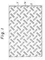
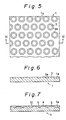
- protrusions 2 in the planar shape formed in the surface 1a of a back metal 1 composed of a rectangular steel plate, in which adjacent protrusions 2 are arranged in the direction perpendicular to each other as shown in Fig. 1 to Fig. 3; and circular protrusions 3 in the planar shape formed in the surface 1a of a back metal 1 composed of a rectangular steel plate as shown in Fig. 5 to Fig. 6.
- the protrusion 2 or 3 has a flat surface and the peripheral portion thereof is formed as an inclined surface 2a or 3a with a downward slope from the flat surface to the surface 1a of the back metal respectively.
- each of the protrusions 4, 6 and 8 has a flat surface and the peripheral portion of each of the recesses 5, 7 and 9 defined with such protrusions is formed as an inclined surface 5a, 7a and 9a with a downward slope from the flat surface to the surface 1a of the back metal.
- a sintered copper alloy 10 formed integrally by securing to the surface of the protrusions formed independently or continuously at the surface 1a of the back metal 1 may comprise 4 to 10 wt.% of tin, 10 to 40 wt.% of nickel, 0.1 to 4 wt.% of phosphorus, not greater than 50 wt.% of iron, not greater than 25 wt.% of manganese, 3 to 10 wt.% of graphite and the balance of copper.
- Tin a constituant of the sintered alloy layer forms bronze by being alloyed with copper as the main ingredient, thereby contributing to the improvement of the strength, the toughness, the mechanical strength and the abrasion resistance of the matrix of the sintered alloy layer. Further, it has an effect of increasing the porosity of the sintered alloy layer in cooperation with nickel described later. If the mixing ratio of tin is less than 4% by weight, the foregoing effect can not be attained sufficiently. If tin is mixed in excess of 10% by weight, it gives undesired effect on the sinterability. Accordingly, the mixing ratio of tin is suitably 4 to 10% by weight, preferably 5 to 8% by weight.
- Nickel diffuses into copper as the main ingredient, thereby contributing to the improvement of the abrasion resistance and the strength of the matrix. Nickel diffuses at the surface of the back metal and the surface of the protrusions formed on the surface of the back metal to alloy the boundary thereof upon sintering, thereby increasing the bonding strength between the sintered alloy layer and the surface of the back metal or the surface of the protrusions formed on the surface of the back metal.
- nickel-phosphorus alloy is present at the boundary between the sintered alloy layer and the surface of the back metal or the surface of the protrusions formed on the surface of the back metal, thereby obtaining an effect of firmly bonding the sintered alloy layer integrally with the surface of the back metal or the surface of the protrusion at the boundary in cooperation with alloying due to the diffusion of nickel.
- nickel has an effect of forming gaps in the sintered alloy layer when it diffuses into copper upon sintering, thereby improving the porosity.
- the foregoing effect can not be obtained sufficiently if the mixing ratio of nickel is less than 10% by weight and no remarkable difference is obtainable with respect to the effect described above even if it is blended in excess of 40% by weight. Accordingly, the mixing ratio of nickel is suitably 10 to 40% by weight, preferably 20 to 30% by weight.
- Phosphorus is partially alloyed with copper as the main ingredient and nickel as described above, thereby improving the strength of the matrix and contributing to the improvement of the abrasion resistance. Since phosphorus has a strong reducing power, it has effects of cleaning the surface of the back metal and the surface of protrusions formed on the surface of the back metal by its reducing effect, and of promoting the alloying of nickel due to diffusion to the surface of the back metal and the surface of the protrusion formed on the surface of the back metal. The effect of the nickel-phosphorus alloy is as has been described above.
- the mixing ratio of phosphorus is suitably 0.1 to 4% by weight, preferably 1 to 2% by weight.
- Graphite has to be mixed at a ratio at least not less than 3% by weight in order to provide self-lubricancy but, if the mixing ratio of graphite is increased and, for example, if it is blended in excess of 10% by weight, this brings about a problem in view of the sinterability and the bonding strength with the back metal and the surface of the protrusions formed on the surface of the back metal. Accordingly, the mixing ratio of graphite is suitably 3 to 10% by weight, preferably 5 to 8% by weight.
- the iron has a less solid solubilization limit to copper, but it has the effect of dispersing into the alloy and, particularly, has the effect of improving the strength of the matrix and increasing the porosity of the sintered alloy layer when copper is diffused into iron upon sintering. Further, iron generally tends to be alloyed with phosphorus to form hard iron phosphorus alloy under the presence of phosphorus, but nickel in the ingredients has the effect of suppressing the alloying in the present invention, and accordingly a relatively great amount of iron upto about 50% by weight, preferably 30 to 40% by weight can be blended.
- Manganese is diffused into copper or copper and iron as the main ingredient(s) to improve the abrasion resistance, and contributes to the improvement of the strength of the matrix. Further, manganese expands the sintered alloy layer, thereby making the sintered alloy layer porous in the course of rapidly diffusing into and alloying with copper and nickel during sintering. However, since manganese has the nature of reacting with a phosphorus-nickel alloy (Ni3P) in a liquid phase, thereby increasing the melting point of the liquid phase, and according the mixture in a large amount thereof inhibits the formation of the sintered alloy layer of increased density. Accordingly, the mixing ratio of the mangenese is appropriately not greater than 25% by weight, preferably 5 to 10% by weight.
- a back metal there is prepared a rectangular steel plate having a plurality of independent protrusions on the surface, in which an inclined surface is formed at the peripheral portion of the protrusion as described above, or a rectangular steel plate having continuous protrusions at the surface, in which a plurality of independent recesses is formed within the protrusions and an inclined surface is formed at the peripheral portion of the recesses.
- the back metal and the surface of the protrusions formed on the surface of the back metal are roughened, for example, by sand blast.
- a homogenously mixed powder comprising 4 to 10 wt.% of tin, 10 to 40 wt.% of nickel, 0.1 to 4 wt.% of phosphorus, not greater than 50 wt% of iron, not greater than 25 wt.% of manganese, 3 to 10 wt.% of graphite and the balance of copper is prepared.
- the mixed powder is uniformly scattered over the surface of the back metal and the surface of the protrusions on the surface of the back metal.
- the back metal having the mixed powder uniformly scattered on the surface is placed in a heating furnace conditioned to a reducing atmosphere and sintered at a temperature of 870 to 920°C for 10 to 20 min (primary sintering) to conduct sintering of the mixed powder and diffuse - bond to the back metal, by which the pre-sintered alloy layer is integrally bonded to the surface of the back metal.
- the back metal having integrally bonded with the pre-sintered alloy layer is rolled by being passed 3 to 4 times between a pair of rollers, thereby increasing the density of the pre-sintered alloy layer.
- the back metal having the pre-sintered alloy layer formed integrally on the surface thereof is placed in the heating furnace as described above and sintered at a temperature of 920 to 1000°C for 10 to 20 min (secondary sintering), to proceed the sintering of the pre-sintered alloy layer and increase the bonding strength with the back metal. Subsequently, it is rolled by being passed once through the rollers, thereby obtaining the multi-layered sintered sliding member having the flattened surface, in which the density of the sintered alloy layer thereof is further increased (Fig. 4, Fig. 7, Fig. 10 and Fig. 13).
- a high density alloy region at the surface of the protrusion (reference numeral a in the drawing) and a low density alloy region at the surface of the back metal (reference numeral b in the drawing) are formed.
- the resultant multi-layered sintered sliding member is subject to an oil-impregnation treatment to obtain an oil-impregnated multi-layered sintered sliding member with a high oil-impregnation rate in the low density alloy region and a low oil-impregnation rate in the high density alloy region of the sintered alloy layer.
- a Step The step is the same as the first step in the production method as described above.
- the starting powder is supplied to a press-roll and molded into a rolled sheet, which is then cut into an appropriate shape.
- D Step The rolled sheet is superposed on the back metal prepared in the A step and is sintered in a heating furnace conditioned to a reducing atmosphere or vacuum at a temperature of 870 to 1000°C under a pressure of 0.1 to 5.0 kgf/cm2 for 20 to 60 min to conduct the sintering of the rolled sheet and the diffusion bonding to the back metal, thereby obtaining a multi-layered sintered sliding member in which the sintered alloy layer is integrally bonded to the surface of the back metal.
- the density and the thickness of the rolled sheet from the starting powder can be controlled by a rolling load and the rolling load depends on a roll speed and a roll gap.
- the density and the thickness of the rolled sheet can properly be adjusted by varying the roll speed and the roll gap.
- peripheral portion of a plurality of independent protrusions or continuous protrusions formed at the surface of the back metal are formed as inclined surfaces, a high bonding strength can be obtained between the protrusions and the sintered alloy layer formed integrally by securing on the surface of the protrusions.
- a sintered alloy region having a low density (5 - 6 g/cm3), preferably a low density (5 - 6 g/cm3) and high oil-impregnation rate (25 to 30 vol%), and a sintered alloy region having a high density (7 - 8 g/cm3) preferably a high density (7 - 8 g/cm3) and low oil-impregnation rate (11 - 14 vol%) are formed.
- the deformation amount ( ⁇ m) for the thickness at an impact load of 3,000 kgf/cm2 is not greater than 47 ⁇ m at 100,000 duration cycles, preferably not greater than 45 ⁇ m at 100,000 duration cycles.
- the friction coefficient of the multi-layered sintered sliding member according to the present invention is 0.15 to 0.3, preferably 0.15 to 0.23; the friction coefficient to the sliding surface under the state of scattering water and dust is not more than 0.42, preferably 0.18 to 0.40, and the abrasion amount is not more than 20 ⁇ m, preferably 16.0 to 18.5 ⁇ m.
- the pressure-resistant strength of the sintered alloy layer can be increased to slidingly support the high load and impact load without causing plastic deformation or the like of the sintered alloy layer against such loads.
- the velocity characteristic (friction coefficient) and the abrasion resistance as the sliding member can be improved remarkably.
- the multi-layered sintered sliding member according to the present invention can be applied to such application or use where high load and impact load are intermittently exerted, such as floor plates for slidingly supporting tongue rails in a railway track point.
- a rectangular steel plate (rolled steel plate SS41) used as a back metal 1 had a plurality of independent rectangular protrusions 2 in the planar shape arranged in the direction perpendicular to each other on a surface 1a, in which the surface of the protrusion 2 was formed as a flat surface and the peripheral portion of the protrusion 2 was formed as an inclined surface 2a with a downward slope from the surface of the protrusion to the surface 1a of the back metal (150 mm of length, 260 mm of width, 8 mm in thickness upto the surface of the back metal and 1.695 mm of height for the protrusion) [Fig. 1 to Fig. 3].
- the ratio of the area for the flat surface of the protrusions 2 formed at the surface 1a of the back metal to the entire surface area was 14%. After degreasing and cleaning the surface 1a of the back metal 1 and the surface of the protrusion 2, they were roughened by sand blasting.
- the back metal 1 having a mixed powder layer uniformly scattered on the surface thereof was placed in a heating furnace conditioned to a reducing atmosphere and sintered at a temperature of 920°C for 10 min (primary sintering) to conduct sintering of the mixed powder and diffusion bonding to the back metal, thereby integrally bonding the sintered alloy layer onto the back metal.
- the back metal having the presintered alloy layer integrally bonded therewith was rolled by being passed for three times between a pair of rollers, thereby increasing the density of the pre-sintered alloy layer.
- the thickness of the pre-sintered alloy layer was 1.5 mm in the sintered alloy layer on the protrusions 2 on the surface of the back metal and 3 mm in the sintered alloy layer on the surface 1a of the back metal.
- the back metal having the pre-sintered alloy layer integrally bonded therewith was placed in the heating furnace described above and sintered at a temperature of 950°C for 10 min (secondary sintering) to proceed the sintering of the pre-sintered alloy layer and increase the bonding strength with the back metal.
- the back metal was rolled by being passed for once between a pair of rollers described above to obtain a multi-layered sintered sliding member, wherein the density of the sintered alloy layer was increased and the surface thereof was flattened with a good accuracy.
- the sintered alloy layer of the thus obtained multi-layered sintered sliding member was formed with a thickness of 1.2 mm on the surface of the protrusions 2 and with a thickness of 2.3 mm on the surface 1a of the back metal, and the density of the sintered alloy layer on the surface of the protrusion 2 was 7.4 g/cm3 and the density of the sintered alloy layer on the surface of the back metal was 5.3 g/cm3.
- Oil-impregnation treatment was applied to the multi-layered sintered sliding member to obtain an oil-impregnated multi-layered sintered sliding member with an oil impregnation rate of 13 vol% in the high-density sintered alloy region on the surface of the protrusions and 29 vol% in the low-density sintered alloy region on the surface of the back metal.
- a rectangular steel sheet (rolled steel plate SS41) used as a back metal 1 had continuous stripe-like protrusions 4 formed in parallel with each other and with intersections at the surface 1a and a plurality of rhombic recesses 5 in the planar shape defined with the protrusions 4 at the surface 1a, in which the surface of the protrusion 4 was formed into a flat surface and the peripheral portion thereof was formed into an inclined surface 5a with a downward slope from the surface of the protrusion to the surface of the back metal (150 mm of length, 260 mm of width, 8 mm in thickness up to the surface of the back metal and 1.695 mm of height for the protrusion) [refer to Fig. 8 and Fig. 9].
- the area ratio of the flat surface of the stripe-like protrusions 4 formed continuously at the surface 1a of the back metal to the entire surface area was 28%. After defatting and cleaning the surface 1a of the back metal 1 and the surface of the protrusions 4, they were roughened by sand blasting.
- the mixed powder was uniformly scattered over the surface 1a of the back metal and the surface of the protrusions 4 at the surface of the back metal, thereby forming a mixed powder layer having a thickness of 3.5 mm on the surface of the protrusions 4 and a thickness of 5.2 mm on the surface 1a of the back metal.
- the back metal 1 having a mixed powder layer uniformly scattered on the surface was placed in a heating furnace conditioned to a reducing atmosphere and sintered at a temperature of 920°C for 10 min (primary sintering) to conduct sintering of the mixed powder and diffusion bonding to the back metal, thereby integrally bonding the pre-sintered alloy layer onto the back metal.
- the back metal having the pre-sintered alloy layer integrally bonded therewith was rolled by being passed for three times between a pair of rollers, thereby increasing the density of the pre-sintered alloy layer.
- the thickness of the pre-sintered alloy layer was 1.5 mm in the sintered alloy layer on the protrusions 4 at the surface of the back metal and 3 mm in the sintered alloy layer on the surface 1a of the back metal.
- the back metal having the pre-sintered alloy layer integrally bonded therewith was placed in the heating furnace described above and sintered at a temperature of 950°C for 10 min (secondary sintering) to proceed the sintering of the pre-sintered alloy layer and increase the bonding strength with the back metal. Subsequently, the back metal was rolled by being passed for once between a pair of rollers described above to obtain a multi-layered sintered sliding member wherein the density of the sintered alloy layer was increased and the surface thereof was flattened with a good accuracy.
- the sintered alloy layer of the thus obtained multi-layered sintered sliding member was formed with a thickness of 1.2 mm on the surface of the protrusions 4 and with a thickness of 2.3 mm on the surface 1a of the back metal, and the density of the sintered alloy layer on the surface of the protrusion 4 was 7.4 g/cm3 and the density of the sintered alloy layer on the surface of the back metal was 5.8 g/cm3.
- Oil-impregnation treatment was applied to the multi-layered sintered sliding member to obtain an oil-impregnated multi-layered sintered sliding member with an oil impregnation rate of 11 vol% in the high density alloy region on the surface of the protrusion and 29 vol% in the low density alloy region on the surface of the back metal.
- a sleepers was fixed on a press bolster of a pressing machine and a load cell was disposed securely by means of a countersunk spring on the sleeper.
- a test specimen multi-layered sintered sliding member
- a mating member is fixed on a press-slide of the pressing machine. Then, the slide was actuated vertically in order to apply an impact load to the test specimen and the deformation amount ( ⁇ m) for the thickness of the test specimen was measured.
- Test Conditions Moving speed of press slide: 80 CPM
- prior art is a multi-layered sintered sliding member disclosed in Japanese Patent Publication 56-1288 described above and existent product is a sliding member in which lubricant is oiled to a rolled steel sheet (SS41).
- the multi-layered sintered sliding members of Example 1 and Example 2 can remarkably improve the impact resistance performance as compared with the multi-layered sintered sliding member of the prior art and they can provide performance as comparable with or superior to that of the oil feed type sliding member of the existent product.
- test specimen was fixed on a base, and a tongue rail is disposed on the test specimen, and a tongue rail is secured to a piston rod of an air cylinder fixed on the side of the base.
- a load is placed on the tongue rail, the cylinder was reciprocated while slidingly supporting the tongue rail on the test specimen and the friction coefficient between both of them was measured.
- the upper limit values for the friction coefficient in (1), (2) and (3) are values upon water scattering, dust scattering or water and dust scattering to the sliding surface, respectively.
- the multi-layered sintered sliding members a Example 1 and Example 2 showed stable friction coefficient under various circumferential conditions with no oil feeding at all after starting the test.
- the friction coefficient and the abrasion amount show the comparable performance with those of the existent product in which lubricant is fed to a rolled steel sheet (SS41).
- the multi-layered sintered sliding member according to the present invention can provide an effect capable of saving manual oiling operation of lubricant.
- the production method can be simplified and the production cost can be reduced.
Landscapes
- Engineering & Computer Science (AREA)
- Mechanical Engineering (AREA)
- General Engineering & Computer Science (AREA)
- Manufacturing & Machinery (AREA)
- Chemical & Material Sciences (AREA)
- Composite Materials (AREA)
- Materials Engineering (AREA)
- Powder Metallurgy (AREA)
- Sliding-Contact Bearings (AREA)
Applications Claiming Priority (2)
| Application Number | Priority Date | Filing Date | Title |
|---|---|---|---|
| JP2027677A JP3024153B2 (ja) | 1990-02-07 | 1990-02-07 | 複層焼結摺動部材 |
| JP27677/90 | 1990-02-07 |
Publications (2)
| Publication Number | Publication Date |
|---|---|
| EP0441624A1 true EP0441624A1 (de) | 1991-08-14 |
| EP0441624B1 EP0441624B1 (de) | 1995-11-15 |
Family
ID=12227597
Family Applications (1)
| Application Number | Title | Priority Date | Filing Date |
|---|---|---|---|
| EP91300996A Expired - Lifetime EP0441624B1 (de) | 1990-02-07 | 1991-02-06 | Mehrschichter, gesinterter Gleitteil |
Country Status (4)
| Country | Link |
|---|---|
| US (1) | US5126212A (de) |
| EP (1) | EP0441624B1 (de) |
| JP (1) | JP3024153B2 (de) |
| DE (1) | DE69114536T2 (de) |
Cited By (3)
| Publication number | Priority date | Publication date | Assignee | Title |
|---|---|---|---|---|
| EP0872654A3 (de) * | 1997-04-19 | 1999-08-11 | Woo Chun Lee | Gleitlager und sein Herstellungsverfahren |
| EP2184121A4 (de) * | 2007-07-31 | 2012-10-03 | Caterpillar Japan Ltd | Mehrschichtiges gesintertes schiebeelement |
| EP2946855A4 (de) * | 2013-01-16 | 2016-08-31 | Oiles Industry Co Ltd | Schiebeplatte und bodenplatte zum herausdrehen |
Families Citing this family (10)
| Publication number | Priority date | Publication date | Assignee | Title |
|---|---|---|---|---|
| JPH0762191B2 (ja) * | 1990-11-29 | 1995-07-05 | 大同メタル工業株式会社 | 焼結銅合金層を有する摺動部材 |
| US5267600A (en) * | 1992-01-21 | 1993-12-07 | Deere & Company | Hard facing casting surfaces with wear-resistant sheets |
| JP3859344B2 (ja) | 1998-01-28 | 2006-12-20 | 株式会社小松製作所 | 摺動材料,摺動部材およびその摺動部材の製造方法 |
| JP4507766B2 (ja) * | 2004-08-27 | 2010-07-21 | 株式会社ダイヤメット | 高強度を示しかつ高温環境下ですぐれた耐摩耗性を示すEGR式内燃機関の再循環排ガス流量制御弁用焼結Cu合金製軸受 |
| CN102773488A (zh) * | 2006-01-16 | 2012-11-14 | 奥依列斯工业株式会社 | 铜类烧结滑动部件 |
| JP5544777B2 (ja) * | 2008-07-30 | 2014-07-09 | キャタピラージャパン株式会社 | 複層焼結摺動部材の製造方法 |
| JP5684977B2 (ja) * | 2009-08-31 | 2015-03-18 | 株式会社ダイヤメット | Cu基焼結摺動部材 |
| JP6779600B2 (ja) * | 2015-07-16 | 2020-11-04 | オイレス工業株式会社 | 複層摺動部材 |
| JP6769007B2 (ja) * | 2017-06-29 | 2020-10-14 | 株式会社ダイヤメット | モータ式燃料ポンプ用焼結軸受及びその製造方法 |
| JP6893836B2 (ja) * | 2017-07-03 | 2021-06-23 | オイレス工業株式会社 | 複層焼結板及びその製造方法 |
Citations (3)
| Publication number | Priority date | Publication date | Assignee | Title |
|---|---|---|---|---|
| GB1200610A (en) * | 1967-12-11 | 1970-07-29 | Duria Werk Karl Kemf G M B H | Process for manufacturing parts provided with a sintered surface layer |
| FR2164685A1 (de) * | 1971-12-20 | 1973-08-03 | Union Carbide Corp | |
| US4505987A (en) * | 1981-11-10 | 1985-03-19 | Oiles Industry Co., Ltd. | Sliding member |
Family Cites Families (8)
| Publication number | Priority date | Publication date | Assignee | Title |
|---|---|---|---|---|
| DE2005681B2 (de) * | 1970-02-07 | 1973-09-27 | Siemens Ag | Kontaktstuck für hohe elektrische Belastung |
| US3885072A (en) * | 1970-10-29 | 1975-05-20 | Ppg Industries Inc | Attachment of rigid members to frangible window panels |
| JPS50150656A (de) * | 1974-05-28 | 1975-12-03 | ||
| CH614749A5 (de) * | 1975-11-24 | 1979-12-14 | Loewe Anstalt | |
| JPS5344408A (en) * | 1976-10-04 | 1978-04-21 | Oiles Industry Co Ltd | Selfflubricating sliding member material |
| JPS62116705A (ja) * | 1985-11-15 | 1987-05-28 | Mazda Motor Corp | わん曲部への焼結層の形成方法 |
| US4767677A (en) * | 1986-09-17 | 1988-08-30 | Ndc Co., Ltd. | Multi-layer cylindrical bearing |
| JPH0791569B2 (ja) * | 1987-10-19 | 1995-10-04 | オイレス工業株式会社 | 複層からなる焼結摺動部材の製造方法 |
-
1990
- 1990-02-07 JP JP2027677A patent/JP3024153B2/ja not_active Expired - Lifetime
-
1991
- 1991-02-06 EP EP91300996A patent/EP0441624B1/de not_active Expired - Lifetime
- 1991-02-06 DE DE69114536T patent/DE69114536T2/de not_active Expired - Fee Related
- 1991-06-27 US US07/726,621 patent/US5126212A/en not_active Expired - Lifetime
Patent Citations (3)
| Publication number | Priority date | Publication date | Assignee | Title |
|---|---|---|---|---|
| GB1200610A (en) * | 1967-12-11 | 1970-07-29 | Duria Werk Karl Kemf G M B H | Process for manufacturing parts provided with a sintered surface layer |
| FR2164685A1 (de) * | 1971-12-20 | 1973-08-03 | Union Carbide Corp | |
| US4505987A (en) * | 1981-11-10 | 1985-03-19 | Oiles Industry Co., Ltd. | Sliding member |
Non-Patent Citations (1)
| Title |
|---|
| WORLD PATENT INDEX, FILE SUPPLIER, abstract AN=87-188088, Derwent Publications Ltd, London, GB; & JP-A-62 116 705 (TOYO KOGYO K.K.) 28-05-1987 * |
Cited By (3)
| Publication number | Priority date | Publication date | Assignee | Title |
|---|---|---|---|---|
| EP0872654A3 (de) * | 1997-04-19 | 1999-08-11 | Woo Chun Lee | Gleitlager und sein Herstellungsverfahren |
| EP2184121A4 (de) * | 2007-07-31 | 2012-10-03 | Caterpillar Japan Ltd | Mehrschichtiges gesintertes schiebeelement |
| EP2946855A4 (de) * | 2013-01-16 | 2016-08-31 | Oiles Industry Co Ltd | Schiebeplatte und bodenplatte zum herausdrehen |
Also Published As
| Publication number | Publication date |
|---|---|
| EP0441624B1 (de) | 1995-11-15 |
| DE69114536D1 (de) | 1995-12-21 |
| DE69114536T2 (de) | 1996-07-04 |
| JP3024153B2 (ja) | 2000-03-21 |
| US5126212A (en) | 1992-06-30 |
| JPH03232905A (ja) | 1991-10-16 |
Similar Documents
| Publication | Publication Date | Title |
|---|---|---|
| EP0441624B1 (de) | Mehrschichter, gesinterter Gleitteil | |
| US6428744B1 (en) | Sliding contact material, sliding contact element and producing method | |
| US4505987A (en) | Sliding member | |
| KR101223789B1 (ko) | 베어링 및 무연 베어링의 제조방법 | |
| JP4424810B2 (ja) | 焼結材料 | |
| AT509981B1 (de) | Verfahren zur herstellung von verbundkörpern sowie danach hergestellte verbundkörper | |
| GB2137660A (en) | Composite material for a sliding member | |
| CA1170482A (en) | Sliding material and method of producing same | |
| GB2181455A (en) | Producing sintered composite sliding parts | |
| EP0604625B1 (de) | Gesinterter bremsklotz für scheibenbremsen | |
| JP4214519B2 (ja) | 銅系摺動材料およびその製造方法 | |
| JP2551981B2 (ja) | 複層鉄銅鉛系合金軸受材料 | |
| JP4462297B2 (ja) | 摺動材料およびその製造方法 | |
| JP3661750B2 (ja) | 複層焼結摺動部材の製造方法 | |
| JP3325033B2 (ja) | 複層焼結摺動部材ならびにその製造方法 | |
| JPH0639605B2 (ja) | 鋳鉄製裏金を有する複層焼結摺動部材 | |
| DE2824257A1 (de) | Sinter-bauteil in elektromagnetischen maschinen | |
| JPH0791569B2 (ja) | 複層からなる焼結摺動部材の製造方法 | |
| JP3578409B2 (ja) | 焼結摺動部材の製造方法 | |
| JP2020097766A (ja) | 摺動部材 | |
| JP2859888B2 (ja) | 二層構造焼結摩擦材 | |
| JP3397332B2 (ja) | 焼結摺動部材ならびにその製造方法 | |
| JPH066721B2 (ja) | 自己潤滑性焼結銅合金の製造方法 | |
| JPH0776570B2 (ja) | 無給油摺動部材 | |
| US20080107558A1 (en) | Sheet Material Infiltration of Powder Metal Parts |
Legal Events
| Date | Code | Title | Description |
|---|---|---|---|
| PUAI | Public reference made under article 153(3) epc to a published international application that has entered the european phase |
Free format text: ORIGINAL CODE: 0009012 |
|
| AK | Designated contracting states |
Kind code of ref document: A1 Designated state(s): DE FR GB |
|
| 17P | Request for examination filed |
Effective date: 19911024 |
|
| 17Q | First examination report despatched |
Effective date: 19930810 |
|
| GRAA | (expected) grant |
Free format text: ORIGINAL CODE: 0009210 |
|
| AK | Designated contracting states |
Kind code of ref document: B1 Designated state(s): DE FR GB |
|
| REF | Corresponds to: |
Ref document number: 69114536 Country of ref document: DE Date of ref document: 19951221 |
|
| ET | Fr: translation filed | ||
| PLBE | No opposition filed within time limit |
Free format text: ORIGINAL CODE: 0009261 |
|
| STAA | Information on the status of an ep patent application or granted ep patent |
Free format text: STATUS: NO OPPOSITION FILED WITHIN TIME LIMIT |
|
| 26N | No opposition filed | ||
| REG | Reference to a national code |
Ref country code: GB Ref legal event code: IF02 |
|
| PGFP | Annual fee paid to national office [announced via postgrant information from national office to epo] |
Ref country code: DE Payment date: 20090129 Year of fee payment: 19 |
|
| PGFP | Annual fee paid to national office [announced via postgrant information from national office to epo] |
Ref country code: GB Payment date: 20090204 Year of fee payment: 19 |
|
| PGFP | Annual fee paid to national office [announced via postgrant information from national office to epo] |
Ref country code: FR Payment date: 20090213 Year of fee payment: 19 |
|
| GBPC | Gb: european patent ceased through non-payment of renewal fee |
Effective date: 20100206 |
|
| REG | Reference to a national code |
Ref country code: FR Ref legal event code: ST Effective date: 20101029 |
|
| PG25 | Lapsed in a contracting state [announced via postgrant information from national office to epo] |
Ref country code: FR Free format text: LAPSE BECAUSE OF NON-PAYMENT OF DUE FEES Effective date: 20100301 |
|
| PG25 | Lapsed in a contracting state [announced via postgrant information from national office to epo] |
Ref country code: DE Free format text: LAPSE BECAUSE OF NON-PAYMENT OF DUE FEES Effective date: 20100901 |
|
| PG25 | Lapsed in a contracting state [announced via postgrant information from national office to epo] |
Ref country code: GB Free format text: LAPSE BECAUSE OF NON-PAYMENT OF DUE FEES Effective date: 20100206 |