EP0442395B1 - Wurfpfeil-Scheibe - Google Patents
Wurfpfeil-Scheibe Download PDFInfo
- Publication number
- EP0442395B1 EP0442395B1 EP91101804A EP91101804A EP0442395B1 EP 0442395 B1 EP0442395 B1 EP 0442395B1 EP 91101804 A EP91101804 A EP 91101804A EP 91101804 A EP91101804 A EP 91101804A EP 0442395 B1 EP0442395 B1 EP 0442395B1
- Authority
- EP
- European Patent Office
- Prior art keywords
- contact
- segment
- contact plate
- target
- elastic
- Prior art date
- Legal status (The legal status is an assumption and is not a legal conclusion. Google has not performed a legal analysis and makes no representation as to the accuracy of the status listed.)
- Expired - Lifetime
Links
- 229910000831 Steel Inorganic materials 0.000 claims description 16
- 239000010959 steel Substances 0.000 claims description 16
- 239000004033 plastic Substances 0.000 claims description 3
- 229920003023 plastic Polymers 0.000 claims description 3
- 210000003739 neck Anatomy 0.000 claims 1
- 238000006073 displacement reaction Methods 0.000 abstract description 2
- 238000011161 development Methods 0.000 description 2
- 230000018109 developmental process Effects 0.000 description 2
- 229920002457 flexible plastic Polymers 0.000 description 2
- 230000001960 triggered effect Effects 0.000 description 2
- 230000015572 biosynthetic process Effects 0.000 description 1
- 239000004020 conductor Substances 0.000 description 1
- 238000005755 formation reaction Methods 0.000 description 1
- 230000003116 impacting effect Effects 0.000 description 1
- 238000012423 maintenance Methods 0.000 description 1
- 230000000717 retained effect Effects 0.000 description 1
- 239000000725 suspension Substances 0.000 description 1
Images




Classifications
-
- F—MECHANICAL ENGINEERING; LIGHTING; HEATING; WEAPONS; BLASTING
- F41—WEAPONS
- F41J—TARGETS; TARGET RANGES; BULLET CATCHERS
- F41J3/00—Targets for arrows or darts, e.g. for sporting or amusement purposes
- F41J3/0009—Dartboards
- F41J3/0033—Dartboards for use with safety darts
- F41J3/0042—Dartboards for use with safety darts having perforations for receiving blunt tip darts
-
- F—MECHANICAL ENGINEERING; LIGHTING; HEATING; WEAPONS; BLASTING
- F41—WEAPONS
- F41J—TARGETS; TARGET RANGES; BULLET CATCHERS
- F41J3/00—Targets for arrows or darts, e.g. for sporting or amusement purposes
- F41J3/0009—Dartboards
- F41J3/0061—Target faces
- F41J3/0066—Segmentation of conventional target faces
-
- F—MECHANICAL ENGINEERING; LIGHTING; HEATING; WEAPONS; BLASTING
- F41—WEAPONS
- F41J—TARGETS; TARGET RANGES; BULLET CATCHERS
- F41J5/00—Target indicating systems; Target-hit or score detecting systems
- F41J5/04—Electric hit-indicating systems; Detecting hits by actuation of electric contacts or switches
- F41J5/052—Targets comprising a plurality of electric contacts, each corresponding to a discrete target section and being actuated by the movement thereof
Definitions
- the invention relates to a dartboard according to the preamble of claim 1.
- Such a dart target is known from GB-A-2 209 959.
- the back of the segments are provided with elastic, pot-shaped "buffer rings".
- a plate made of a conductive material is arranged within each buffer ring.
- Associated contact points are arranged on the side of the dartboard disc opposite the plates.
- the object of the invention is to improve the reliability of the hit display in a dart target of the type mentioned.
- the contact cap is constantly supported on only one side of the contact point on the contact plate.
- the contact cap is also supported in the rest position next to the contact point. The less protruding area of the contact cap is spaced from the contact point in the rest position. When a hit occurs, this area triggers the contact by connecting two contacts within the contact plate.
- the contact is made directly on the contact plate without a rubber mat.
- the Dart segment can be taken out of the scaffold to the rear, i.e. from the service side.
- a further advantageous development is characterized in that steel segments extending in the transverse direction are provided which project beyond the side walls of the segments and which delimit in elongated holes in the spokes and / or tires are slidably mounted.
- the elongated holes of the spokes and / or tires are arranged and dimensioned such that no contact is triggered in the rest position, but that a reliable hit display is guaranteed when a dart hits.
- the steel axes carry resilient, the contact-forming elements, which consist of a first, resilient sub-element, which rests in the rest position under prestress on the contact plate next to the contact point, and a second sub-element which is spaced apart from the contact point in the rest position and triggers the contact when hit.
- the dart segment can be removed to the rear, i.e. from the service side.
- a rubber mat is not required.
- Each resilient element consists of two sub-elements.
- the contact plate can be transparent. Another, preferably also transparent, plate can be located behind the contact plate. The arrangement and dimensions are such that a partial element of each spring element always bears against the back plate (contact plate) under a certain pretension.
- the sub-element lying directly next to it does not abut the contact plate.
- a system is only created when the segment is hit by a dart, so that the contact is triggered.
- the multi-layer contact plate (contact surface) is located between the back of the segments and the rear plate.
- the contacts are arranged in such a way that there are no contacts at the constantly loaded points, rather they are located above or below the second sub-elements, which are only pushed back when a hit is made.
- the second sub-element can also be elastic.
- the resilient elements can be rotationally symmetrical.
- the resilient elements can consist of rubber-like, elastic bodies, preferably of flexible plastic.
- the resilient elements can consist of two thickened areas with a smaller size or diameter area in between.
- the use of flexible plastics is particularly advantageous since there are such plastics that injected and thus can be manufactured particularly easily.
- the elastic bodies sit on the steel axes that penetrate the segment and protrude from the sides of the segment so that they limit the movement of the segment to the front.
- An interference fit can be provided between the axes and the segments so that the axes can no longer shift later and possibly interfere with an adjacent segment. Formations for stiffening the segment can be provided on the side surfaces of the segments.
- each segment can be fully assembled and is only then inserted into the scaffolding. A complete pre-assembly of each segment is therefore possible before the final assembly on the scaffolding itself. This also has significant advantages in terms of maintenance: if a segment has to be removed, it can simply be removed. In previous solutions, it was necessary to remove at least two strips on the spokes or tires on the back of the scaffold. If the spring elements are used up, the segment can also be easily replaced.
- a pre-tensioned segment in the frame is achieved by the pre-tensioning.
- a practical advantage results from the fact that after a hit the dart does not swing or flutter.
- there is no pretension because the rubber mat required for the suspension or spring loading cannot be pretensioned there.
- a pre-tensioned rubber mat would be destroyed by the permanent load at the support points.
- a hit display would always appear with a pre-tensioned rubber mat.
- the rubber mat is available over the whole area and in one piece for all segments and must therefore be designed with a certain minimum hardness (Shore hardness) in order to enable a reliable hit display at all. Accordingly, in the proposed solution, all segments are self-sufficient and equipped with separate elastic elements.
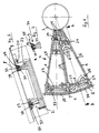
- the dartboard consists of a frame with spokes 1 and tires 2, which delimit a large number of fields 3 between them, in each of which a spring-loaded segment 4 is axially displaceably guided.
- the segment 4 has a target area 5 with a multiplicity of holes 6 for receiving the dart, of which only a single hole is shown in FIG. 2. 1 there are several, but not all, holes to see.
- Each hole 6 has a conical widening on the side of the hit surface 5 to make it easier to pick up the dart.
- the dart segment 4 is guided axially displaceably within its field 3 lying between the spokes 1 and the tires 2.
- the dartboard consists of a carrier plate 8 and a printed circuit board (contact plate) 9 located thereon.
- the contact plate 9 has contacts for displaying hits for each segment 4.
- transverse steel axes 23, 24 are provided, which protrude beyond the side walls 25 of the segments 4 and which are mounted to be displaceable to a limited extent in the elongated holes of the spokes 1.
- the segments 4 In the vicinity of the steel axes 23, 24, the segments 4 have pins 33 pointing backwards, on each of which an elastic contact cap 34 which triggers the hit contact is arranged.
- Each contact cap 34 has a further projecting area 35, with which it is constantly next to the contact point 36 on the contact plate 9 supports, and a less protruding area 37 which is spaced apart from the contact point 36 in the rest position and which triggers the contact when hit.
- the elastic cap (contact cap) 34 is attached to the pin 33.
- the contact cap 34 is supported next to the contact point 36 and presses the dart segment 4 away from the printed circuit board (contact plate). A rubber mat is therefore not required.
- the dart segment is constantly under tension.
- FIGS. 4 to 6 has shortened steel axes 23, 24.
- steel axes 23, 24 are again provided, which run in the transverse direction in the segments 4. As can be seen from FIG. 7, the steel axes 23 can be bent.
- the steel axes 23, 24 carry resilient elements 38, which consist of a first, resilient partial element 39, which rests under prestress on the contact plate 9 next to the contact point 36 (FIG. 9) and from a second partial element 40, which is in the rest position is spaced from the contact point 36 and which triggers the contact upon a hit.
- the second sub-element 40 is also elastic.
- the resilient elements 38 are rotationally symmetrical. They consist of rubber-like elastic bodies made of soft elastic Plastic.
- the resilient elements 38 consist of two thickened areas 39, 40, namely the first partial element 39 and the second partial element 40, between which there is an area 41 with a smaller diameter.
- the resilient element 38 rests under prestress on the contact plate 9, namely at a distance from the contact point 36.
- the second element 40 touches the contact plate 9 at the contact point 36.
- the steel axis 23 rests on a trough-shaped recess 43 in the side wall 25 of the dart segment 4. At this bearing point, the steel axis 23 therefore has a certain possibility of displacement.
- the steel axis is supported on the edge 44 of the spoke 1. The segment 4 is retained in this way.
- the elastic roller 38 is supported with its large diameter 39 next to the contact point 36 on the circuit board 9; it resiliently rests the dart segment 4 and keeps it under pressure.
- a thrown arrow 42 moves the dart segment 4 in the direction of the printed circuit board 9, as a result of which the large diameter 39 of the elastic roller 38 is compressed and the small diameter 40 touches the contact point 36 and leads to contact. It can be seen from the illustration in FIG. 8 that only the steel axis 23 bears against the spoke 1, but not the segment 4 or its side wall 25.
Landscapes
- General Engineering & Computer Science (AREA)
- Engineering & Computer Science (AREA)
- Toys (AREA)
- Aiming, Guidance, Guns With A Light Source, Armor, Camouflage, And Targets (AREA)
- Inorganic Insulating Materials (AREA)
- Medicinal Preparation (AREA)
- Switches Operated By Changes In Physical Conditions (AREA)
- Acyclic And Carbocyclic Compounds In Medicinal Compositions (AREA)
- Crystals, And After-Treatments Of Crystals (AREA)
- Refuge Islands, Traffic Blockers, Or Guard Fence (AREA)
- Tires In General (AREA)
- Portable Nailing Machines And Staplers (AREA)
- Automatic Assembly (AREA)
- Braking Arrangements (AREA)
Description
- Die Erfindung betrifft eine Wurfpfeil-Scheibe nach dem Oberbegriff des Anspruchs 1.
- Eine derartige Wurfpfeil-Scheibe ist aus der GB-A-2 209 959 bekannt. Dort sind die Rückseiten der Segmente mit elastischen, topfförmigen "Puffer-Ringen" versehen. Innerhalb jedes Puffer-Ringes ist eine aus einem leitenden Material bestehende Platte angeordnet. An der den Platten gegenüberliegenden Seite der Wurfpfeil-Scheibe sind zugehörige Kontaktstellen angeordnet. Wenn das Segment von einem Wurfpfeil getroffen wird, verformen sich die mit ihm verbundenen Puffer-Ringe, so daß die in der Mitte des Puffer-Rings vorgesehene Platte mit der zugehörigen Kontaktstelle in Kontakt tritt, wodurch ein elektrischer Stromkreis geschlossen und die Trefferanzeige bewirkt wird.
- Aufgabe der Erfindung ist es, bei einer Wurfpfeil-Scheibe der eingangs angegebenen Art die Zuverlässigkeit der Trefferanzeige zu verbessern.
- Erfindungsgemäß wird diese Aufgabe durch die im kennzeichnenden Teil des Anspruchs 1 angegebenen Merkmale gelöst. Die Kontaktkappe stützt sich ständig nur auf einer Seite der Kontaktstelle an der Kontaktplatte ab. Die Kontaktkappe stützt sich auch in der Ruhelage neben der Kontaktstelle ab. Der weniger vorstehende Bereich der Kontaktkappe ist in der Ruhelage von der Kontaktstelle beabstandet. Bei einem Treffer löst dieser Bereich den Kontakt aus, und zwar dadurch, daß innerhalb der Kontaktplatte zwei Kontakte miteinander verbunden werden. Bei der Wurfpfeil-Scheibe ist keine elastische Gummimatte vorhanden. Die Kontaktierung erfolgt ohne Gummimatte unmittelbar auf der Kontaktplatte. Das Dartsegment kann nach hinten, also von der Serviceseite her, aus dem Gerüst genommen werden.
- Vorteilhafte Weiterbildungen sind Gegenstand der Unteransprüche.
- Eine weitere vorteilhafte Weiterbildung ist dadurch gekennzeichnet, daß in den Segmenten in Querrichtung verlaufende Stahlachsen vorgesehen sind, die die Seitenwände der Segmente überragen und die in Langlöchern der Speichen und/oder Reifen begrenzt verschieblich gelagert sind. Auch hier sind die Langlöcher der Speichen und/oder Reifen so angeordnet und bemessen, daß in der Ruhelage kein Kontakt ausgelöst wird, daß aber bei Auftreffen eines Wurfpfeils eine zuverlässsige Trefferanzeige gewährleistet ist.
- Nach einer weiteren Ausführungsform tragen die Stahlachsen federnde, die Kontakthappe bildende Elemente, die aus einem ersten, federnden Teilelement bestehen, das in Ruhelage unter Vorspannung an der Kontaktplatte neben der Kontaktstelle anliegt, und aus einem zweiten Teilelement, das in Ruhelage von der Kontaktstelle beabstandet ist und bei einem Treffer den Kontakt auslöst. Auch hier kann das Dartsegment nach hinten, also von der Serviceseite her, entfernt werden. Eine Gummimatte ist nicht erforderlich. Jedes federnde Element besteht aus zwei Teilelementen. Die Kontaktplatte kann durchsichtig sein. Hinter der Kontaktplatte kann sich eine weitere, vorzugsweise ebenfalls durchsichtige Platte befinden. Die Anordnung und Abmessung ist derart getroffen, daß ein Teilelement jedes Federelements stets an der Rückplatte (Kontaktplatte) unter einer gewissen Vorspannung anliegt. Das unmittelbar daneben liegende Teilelement liegt nicht an der Kontaktplatte an. Eine Anlage erfolgt erst dann, wenn das Segment von einem Wurfpfeil getroffen wird, so daß dadurch dann der Kontakt ausgelöst wird. Zwischen der Rückseite der Segmente und der hinteren Platte befindet sich die mehrlagige Kontaktplatte (Kontaktierungsfläche). Die Kontakte sind derart angeordnet, daß an den ständig belasteten Stellen keine Kontakte liegen, diese sich vielmehr über bzw. unter den zweiten Teilelementen befinden, die nur bei einem Treffer nach hinten gedrückt werden.
- Auch das zweite Teilelement kann elastisch sein.
- Die federnden Elemente können rotationssymmetrisch sein.
- Die federnden Elemente können aus gummiartigen, elastischen Körpern bestehen, vorzugsweise aus weichelastischem Kunststoff. Die federnden Elemente können aus zwei verdickten Bereichen mit einem in den Abmessungen bzw. im Durchmesser geringeren Bereich dazwischen bestehen. Die Verwendung weichelastischer Kunststoffe ist besonders vorteilhaft, da es derartige Kunststoffe gibt, die gespritzt und damit besonders einfach hergestellt werden können. Die elastischen Körper sitzen auf den Stahlachsen, die das Segment durchsetzen und an den Seiten des Segments herausragen, so daß sie die Bewegung des Segments nach vorne begrenzen. Zwischen den Achsen und den Segmenten kann eine Preßpassung vorgesehen sein, damit sich die Achsen später nicht mehr verschieben und möglicherweise ein benachbartes Segment stören können. An den Seitenflächen der Segmente können Anformungen zur Versteifung des Segments vorgesehen sein.
- Durch die soeben beschriebene Ausführungsform können folgende Vorteile erreicht werden. Auch im Ruhezustand des Segments ist das Segment vorgespannt. Wenn auch das zweite Teilelement federnd ausgestaltet ist, wird die Kontaktierungsfläche geschont. Außerdem verteilt sich der Druck eines auftreffenden Pfeiles dann auf die Gesamtfläche der beiden federnden Teilelemente. Ein weiterer Vorteil besteht darin, daß die Gummimatte eingespart wird; die Elastizität wird durch die federnden Elemente erzeugt. Auch bei der Montage ergeben sich wesentliche Vorteile: Jedes Segment kann vollständig fertig montiert werden und wird erst dann in das Gerüst eingesetzt. Es ist also eine komplette Vormontage jedes Segments möglich, bevor die Endmontage an dem Gerüst selbst erfolgt. Hierdurch erheben sich auch wesentliche Vorteile bei der Wartung: Wenn ein Segment entfernt werden muß, kann es einfach herausgenommen werden. Bei früheren Lösungen war es erforderlich, zusätzlich mindestens zwei Leisten an den Speichen bzw. Reifen auf der Rückseite des Gerüsts zu entfernen. Wenn die federnden Elemente verbraucht sein sollten, kann ebenfalls das Segment einfach ausgewechselt werden.
- Durch die Vorspannung wird ein spielfrei in dem Gerüst sitzendes Segment erreicht. Als praktischer Vorteil ergibt sich daraus, daß nach einem Treffer der Wurfpfeil nicht schwenkt oder flattert. Bei den bisher bekannten Lösungen ist keine Vorspannung vorhanden, weil dort die für die Federung bzw. Federbelastung erforderliche Gummimatte nicht vorgespannt werden kann. Zum einen würde nämlich eine vorgespannte Gummimatte durch die Dauerbelastung an den Auflagestellen zerstört. Zum anderen würde bei einer vorgespannten Gummimatte ständig eine Trefferanzeige erfolgen. Bei der Verwendung einer Gummimatte ist es in der Praxis nicht möglich, die Segmente vorzuspannen. Die Gummimatte ist nämlich ganzflächig und einstückig für alle Segmente vorhanden und muß daher mit einer bestimmten Mindesthärte (Shore-Härte) ausgeführt werden, um überhaupt eine zuverlässige Trefferanzeige zu ermöglichen. Demgemäß sind bei der vorgeschlagenen Lösung alle Segmente autark und mit gesonderten elastischen Elementen bestückt.
- Ausführungsbeispiele der Erfindung werden nachstehend anhand der beigefügten Zeichnung im einzelnen erläutert. In der Zeichnung zeigt
- Fig. 1
- ein Ausführungsbeispiel der Erfindung in einer Ansicht von unten,
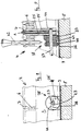
- Fig. 2
- einen Schnitt längs der Linie A-A in Fig. 1,
- Fig. 3
- eine Einzelheit aus der Fig. 2,
- Fig. 4
- eine Variante des in Fig. 1 gezeigten Dartsegments,
- Fig. 5
- einen Schnitt längs der Linie A-A in Fig. 4,
- Fig. 6
- eine Einzelheit aus der Fig. 5,
- Fig. 7
- ein weiteres Ausführungsbeispiel in einer Ansicht von unten,
- Fig. 8
- eine Einzelheit des Dartsegments gemäß Fig. 7,
- Fig. 9
- eine weitere Einzelheit des Dartsegments gemäß Fig. 7,
- Fig. 10
- das Dartsegment der Fig. 7 in einer schematischen Darstellung,
- Fig. 11
- eine Einzelheit aus der Fig. 8,
- Fig. 12
- das in Fig. 10 dargestellte Dartsegment in einer Seitenansicht, teilweise im Schnitt,
- Fig. 13
- eine Variante des in Fig. 7 gezeigten Dartsegments,
- Fig. 14
- eine Einzelheit des in Fig. 13 dargestellten Dartsegments und
- Fig. 15
- eine weitere Einzelheit des Dartsegments gemäß Fig. 13.
- In den Fig. 1 bis 3 ist eine erste Ausführungsform dargestellt. Die Wurfpfeil-Scheibe besteht aus einem Gerüst mit Speichen 1 und Reifen 2, die zwischen sich eine Vielzahl von Feldern 3 begrenzen, in denen jeweils ein federbelastetes Segment 4 axialverschieblich geführt ist. Das Segment 4 besitzt eine Trefferfläche 5 mit einer Vielzahl von Löchern 6 zur Aufnahme des Wurfpfeils, von denen in der Fig. 2 jeweils nur ein einziges Loch gezeigt ist. In der Fig. 1 sind mehrere, aber nicht alle Löcher zu sehen. Jedes Loch 6 besitzt auf der Seite der Trefferfläche 5 eine konische Erweiterung zur Erleichterung der Aufnahme des Wurfpfeils.
- Das Dartsegment 4 ist innerhalb seines zwischen den Speichen 1 und den Reifen 2 liegenden Feldes 3 axialverschieblich geführt.
- Die Wurfpfeil-Scheibe besteht aus einer Trägerplatte 8 und einer darauf befindlichen Leiterplatte (Kontaktplatte) 9. Die Kontaktplatte 9 besitzt Kontakte zur Anzeige von Treffern für jedes Segment 4.
- In dem Segment 4 sind in Querrichtung verlaufende Stahlachsen 23, 24 vorgesehen, die die Seitenwände 25 der Segmente 4 überragen und die in Langlöchern der Speichen 1 begrenzt verschieblich gelagert sind.
- Die Segmente 4 besitzen in der Nähe der Stahlachsen 23, 24 nach hinten weisende Zapfen 33, an denen jeweils eine elastische, den Trefferkontakt auslösende Kontaktkappe 34 angeordnet ist. Jede Kontaktkappe 34 besitzt einen weiter vorstehenden Bereich 35, mit dem sie sich ständig neben der Kontaktstelle 36 an der Kontaktplatte 9 abstützt, und einen weniger vorstehenden Bereich 37, der in Ruhelage von der Kontaktstelle 36 beabstandet ist und der bei einem Treffer den Kontakt auslöst. Die elastische Kappe (Kontaktkappe) 34 ist auf dem Zapfen 33 befestigt. Die Kontaktkappe 34 stützt sich neben der Kontaktstelle 36 ab und drückt das Dartsegment 4 von der Leiterplatte (Kontaktplatte) weg. Eine Gummimatte wird also nicht benötigt. Das Dartsegment liegt ständig unter Vorspannung an. Ein geworfener Pfeil, der auf das Dartsegment auftrifft, bewegt das Dartsegment 4 zur Leiterplatte (Kontaktplatte) 9. Durch die seitliche Abstützung der Kontaktkappe 34 auf deren weiter vorstehenden Bereich 35 wird diese elastische Kontaktkappe 34 vom Zapfen 33 durchgewölbt und führt so mit ihrem weniger vorstehenden Bereich 37 zur Kontaktierung der Kontaktstelle 36 auf der Kontaktplatte 9. Die beschriebene Kontaktierung durch eine elastische Kontaktkappe 34 (ohne Gummimatte) ist mit allen Rückhaltemöglichkeiten der Dartsegmente 4 kombinierbar.
- Die Variante der Fig. 4 bis 6 besitzt im Unterschied zur Ausführungsform der Fig. 1 bis 3 verkürzte Stahlachsen 23, 24.
- Bei der Ausführungsform der Fig. 7 bis 15 sind wiederum Stahlachsen 23, 24 vorgesehen, die in den Segmenten 4 in Querrichtung verlaufen. Wie aus Fig. 7 ersichtlich, können die Stahlachsen 23 abgekröpft sein. Die Stahlachsen 23, 24 tragen federnde Elemente 38, die aus einem ersten, federnden Teilelement 39 bestehen, das in Ruhelage unter Vorspannung an der Kontaktplatte 9 neben der Kontaktstelle 36 (Fig. 9) anliegt, und aus einem zweiten Teilelement 40, das in Ruhelage von der Kontaktstelle 36 beabstandet ist und das bei einem Treffer den Kontakt auslöst. Im Ausführungsbeispiel ist auch das zweite Teilelement 40 elastisch. Weiterhin sind die federnden Elemente 38 rotationssymmetrisch. Sie bestehen aus gummiartigen elastischen Körpern aus weichelastischem Kunststoff. Die federnden Elemente 38 bestehen aus zwei verdickten Bereichen 39, 40, nämlich dem ersten Teilelement 39 und dem zweiten Teilelement 40, zwischen denen sich ein im Durchmesser geringerer Bereich 41 befindet. Das federnde Element 38 liegt in der Ruhelage unter Vorspannung an der Kontaktplatte 9 an, und zwar im Abstand von der Kontaktstelle 36. Beim Auftreffen eines Wurfpfeils 42 in ein Loch 6 des Segments 4 berührt das zweite Element 40 die Kontaktplatte 9 an der Kontaktstelle 36. Wie aus Fig. 8 ersichtlich, liegt die Stahlachse 23 auf einer wannenförmigen Vertiefung 43 der Seitenwand 25 des Dartsegments 4 auf. An dieser Lagerstelle hat die Stahlachse 23 also eine gewisse Verschiebemöglichkeit. Beim Herausziehen des Pfeiles 42 aus dem Segment stützt sich die Stahlachse an der Kante 44 der Speiche 1 ab. Das Segment 4 wird auf diese Weise zurückgehalten. Die elastische Rolle 38 stützt sich mit ihrem großen Durchmesser 39 neben der Kontaktstelle 36 auf der Leiterplatte 9 ab; sie stellt das Dartsegment 4 federnd zurück und hält es unter Druck. Ein geworfener Pfeil 42 verschiebt das Dartsegment 4 in Richtung zur Leiterplatte 9, wodurch der große Durchmesser 39 der elastischen Rolle 38 zusammengedrückt wird und der kleine Durchmesser 40 die Kontaktstelle 36 berührt und zur Kontaktierung führt. Aus der Darstellung in Fig. 8 wird ersichtlich, daß nur die Stahlachse 23 an der Speiche 1 anliegt, nicht aber das Segment 4 bzw. dessen Seitenwand 25.
- Bei der Variante der Fig. 13 bis 15 sind gegenüber der Ausführungsform der Fig. 7 bis 12 die Stahlachsen 23, 24 verkürzt.
Claims (4)
- Wurfpfeil-Scheibe, bestehend auseinem Gerüst mit Speichen (1) und Reifen (2), die zwischen sich eine Vielzahl von Feldern (3) begrenzen, in denen jeweils ein federbelastetes Segment (4) axialverschieblich geführt ist,und einer Kontaktplatte (9) mit Kontakten zur Anzeige von Treffern für jedes Segment (4),wobei die Segmente (4) nach hinten weisende Zapfen (33) besitzen, an denen jeweils ein elastische, den Trefferkontakt auslösende Kontaktkappe (34,38) angeordnet ist, die einen weiter vorstehenden Bereich (35) aufweist, mit dem sie sich ständig neben der Kontaktstelle (36) an der Kontaktplatte (9) abstützt, und einen weniger vorstehenden Bereich (37), der in Ruhelage von der Kontaktstelle (36) beabstandet ist und der bei einem Treffer den Kontakt auslöst,dadurch gekennzeichnet,
daß sich die Kontaktkappe (34,38) ständig nur auf einer Seite der Kontaktstelle (36) an der Kontaktplatte (9) abstützt. - Wurfpfeil-Scheibe nach Anspruch 1, dadurch gekennzeichnet, daß in den Segmenten (4) in Querrichtung verlaufende Stahlachsen (23, 24) vorgesehen sind, die die Seitenwände (25) der Segmente (4) überragen und die in Langlöchern der Speichen (1) und/oder Reifen (2) begrenzt verschieblich gelagert sind.
- Wurfpfeil-Scheibe nach Anspruch 2, dadurch gekennzeichnet, daß die Stahlachsen (23, 24) federnde, die Kontaktkappe bildende Elemente (38) tragen, die aus einem ersten, federnden Teilelement (39) bestehen, das in Ruhelage unter Vorspannung an der Kontaktplatte (9) neben der Kontaktstelle (36) anliegt, und aus einem zweiten Teilelement (40), das in Ruhelage von der Kontaktstelle (36) beabstandet ist und das bei einem Treffer den Kontakt auslöst, wobei vorzugsweise auch das zweite Teilelement elastisch ist, wobei ferner vorzugsweise die federnden Elemente (38) rotationssymmetrisch sind.
- Wurfpfeil-Scheibe nach Anspruch 3, dadurch gekennzeichnet, daß die federnden Elemente (38) aus gummiartigen elastischen Körpern, vorzugsweise aus weichelastischem Kunststoff bestehen, wobei vorzugsweise die federnden Elemente (38) aus zwei verdickten Bereichen (39, 40) mit einem in den Abmessungen bzw. im Durchmesser geringeren Bereich (41) dazwischen bestehen.
Priority Applications (4)
| Application Number | Priority Date | Filing Date | Title |
|---|---|---|---|
| EP94119526A EP0648995B1 (de) | 1990-02-13 | 1991-02-08 | Wurfpfeil-Scheibe |
| EP94119546A EP0648996B1 (de) | 1990-02-13 | 1991-02-08 | Wurfpfeil-Scheibe |
| EP94119547A EP0645598B1 (de) | 1990-02-13 | 1991-02-08 | Wurfpfeil-Scheibe |
| EP94119527A EP0653602B1 (de) | 1990-02-13 | 1991-02-08 | Wurfpfeil-Scheibe |
Applications Claiming Priority (2)
| Application Number | Priority Date | Filing Date | Title |
|---|---|---|---|
| DE4004409 | 1990-02-13 | ||
| DE4004409A DE4004409C2 (de) | 1990-02-13 | 1990-02-13 | Wurfpfeil-Scheibe |
Related Child Applications (8)
| Application Number | Title | Priority Date | Filing Date |
|---|---|---|---|
| EP94119546.3 Division-Into | 1991-02-08 | ||
| EP94119526A Division EP0648995B1 (de) | 1990-02-13 | 1991-02-08 | Wurfpfeil-Scheibe |
| EP94119546A Division EP0648996B1 (de) | 1990-02-13 | 1991-02-08 | Wurfpfeil-Scheibe |
| EP94119547.1 Division-Into | 1991-02-08 | ||
| EP94119526.5 Division-Into | 1991-02-08 | ||
| EP94119527A Division EP0653602B1 (de) | 1990-02-13 | 1991-02-08 | Wurfpfeil-Scheibe |
| EP94119547A Division EP0645598B1 (de) | 1990-02-13 | 1991-02-08 | Wurfpfeil-Scheibe |
| EP94119527.3 Division-Into | 1994-12-09 |
Publications (3)
| Publication Number | Publication Date |
|---|---|
| EP0442395A2 EP0442395A2 (de) | 1991-08-21 |
| EP0442395A3 EP0442395A3 (en) | 1992-07-08 |
| EP0442395B1 true EP0442395B1 (de) | 1996-11-13 |
Family
ID=6400051
Family Applications (6)
| Application Number | Title | Priority Date | Filing Date |
|---|---|---|---|
| EP91101804A Expired - Lifetime EP0442395B1 (de) | 1990-02-13 | 1991-02-08 | Wurfpfeil-Scheibe |
| EP94119527A Expired - Lifetime EP0653602B1 (de) | 1990-02-13 | 1991-02-08 | Wurfpfeil-Scheibe |
| EP94119547A Expired - Lifetime EP0645598B1 (de) | 1990-02-13 | 1991-02-08 | Wurfpfeil-Scheibe |
| EP94119526A Expired - Lifetime EP0648995B1 (de) | 1990-02-13 | 1991-02-08 | Wurfpfeil-Scheibe |
| EP94119546A Expired - Lifetime EP0648996B1 (de) | 1990-02-13 | 1991-02-08 | Wurfpfeil-Scheibe |
| EP97103625A Ceased EP0781974A3 (de) | 1990-02-13 | 1991-02-08 | Wurfpfeil-Scheibe |
Family Applications After (5)
| Application Number | Title | Priority Date | Filing Date |
|---|---|---|---|
| EP94119527A Expired - Lifetime EP0653602B1 (de) | 1990-02-13 | 1991-02-08 | Wurfpfeil-Scheibe |
| EP94119547A Expired - Lifetime EP0645598B1 (de) | 1990-02-13 | 1991-02-08 | Wurfpfeil-Scheibe |
| EP94119526A Expired - Lifetime EP0648995B1 (de) | 1990-02-13 | 1991-02-08 | Wurfpfeil-Scheibe |
| EP94119546A Expired - Lifetime EP0648996B1 (de) | 1990-02-13 | 1991-02-08 | Wurfpfeil-Scheibe |
| EP97103625A Ceased EP0781974A3 (de) | 1990-02-13 | 1991-02-08 | Wurfpfeil-Scheibe |
Country Status (4)
| Country | Link |
|---|---|
| EP (6) | EP0442395B1 (de) |
| AT (5) | ATE165654T1 (de) |
| DE (7) | DE4042477C2 (de) |
| ES (4) | ES2093036T3 (de) |
Families Citing this family (7)
| Publication number | Priority date | Publication date | Assignee | Title |
|---|---|---|---|---|
| DE4214364C2 (de) * | 1992-04-30 | 1998-07-16 | Nsm Ag | Wurfpfeil-Scheibe |
| US5626344A (en) * | 1995-07-10 | 1997-05-06 | Huang; Chun-Mu | Double bull's-eye device |
| ES2146496B1 (es) * | 1996-02-05 | 2001-02-16 | Quetglas Arino Miguel Angel | Perfeccionamientos en la construccion de armazones de celosia, para el alojamiento y retencion, desplazable, de los segmentos en dianas para el juego de dardos. |
| ES2140270B1 (es) * | 1996-10-16 | 2000-09-01 | Inter Therm S L | Sistema de construccion de una diana para aparatos recreativos electromecanicos. |
| US5848792A (en) * | 1997-06-05 | 1998-12-15 | Valley Recreation Products Inc. | Target construction |
| TW333329U (en) * | 1997-08-01 | 1998-06-01 | kun-lin Zhuo | Improved structure of a dart board |
| TW362766U (en) * | 1998-09-09 | 1999-06-21 | kun-lin Zhuo | Improvement for constitution of target block of dart target |
Family Cites Families (8)
| Publication number | Priority date | Publication date | Assignee | Title |
|---|---|---|---|---|
| US4057251A (en) * | 1976-05-10 | 1977-11-08 | Arachnid, Incorporated | Dart game with apertured target plates resiliently mounted |
| US4516781A (en) * | 1982-11-17 | 1985-05-14 | Industrial Design Electronic Associates, Inc. | Dart game with two microcomputers |
| US4561660A (en) * | 1983-11-14 | 1985-12-31 | Arachnid, Inc. | Dart machine with electronic matrix |
| US4586716A (en) * | 1984-04-17 | 1986-05-06 | Industrial Design Electronic Associates, Inc. | Double bullseye for dart game |
| US4635940A (en) * | 1985-06-26 | 1987-01-13 | William E. McClure | Dart board assembly for an electronic dart game |
| AU7790287A (en) * | 1987-09-21 | 1989-03-09 | Lin, J. | Circuitry for electronic scoring dartboard |
| US4836556A (en) * | 1987-12-11 | 1989-06-06 | Kidde Recreational Products Inc. | Dart game target construction |
| DE3834625A1 (de) * | 1988-08-08 | 1990-02-15 | Nsm Apparatebau Gmbh Kg | Wurfpfeil-scheibe |
-
1990
- 1990-02-13 DE DE4042477A patent/DE4042477C2/de not_active Expired - Fee Related
- 1990-02-13 DE DE4004409A patent/DE4004409C2/de not_active Expired - Fee Related
-
1991
- 1991-02-08 ES ES91101804T patent/ES2093036T3/es not_active Expired - Lifetime
- 1991-02-08 AT AT94119547T patent/ATE165654T1/de not_active IP Right Cessation
- 1991-02-08 EP EP91101804A patent/EP0442395B1/de not_active Expired - Lifetime
- 1991-02-08 AT AT91101804T patent/ATE145279T1/de active
- 1991-02-08 EP EP94119527A patent/EP0653602B1/de not_active Expired - Lifetime
- 1991-02-08 EP EP94119547A patent/EP0645598B1/de not_active Expired - Lifetime
- 1991-02-08 EP EP94119526A patent/EP0648995B1/de not_active Expired - Lifetime
- 1991-02-08 EP EP94119546A patent/EP0648996B1/de not_active Expired - Lifetime
- 1991-02-08 AT AT94119527T patent/ATE180051T1/de not_active IP Right Cessation
- 1991-02-08 ES ES94119526T patent/ES2115142T3/es not_active Expired - Lifetime
- 1991-02-08 AT AT94119526T patent/ATE165655T1/de not_active IP Right Cessation
- 1991-02-08 DE DE59108975T patent/DE59108975D1/de not_active Expired - Fee Related
- 1991-02-08 DE DE59108974T patent/DE59108974D1/de not_active Expired - Fee Related
- 1991-02-08 ES ES94119546T patent/ES2115143T3/es not_active Expired - Lifetime
- 1991-02-08 EP EP97103625A patent/EP0781974A3/de not_active Ceased
- 1991-02-08 DE DE59108335T patent/DE59108335D1/de not_active Expired - Fee Related
- 1991-02-08 DE DE59108976T patent/DE59108976D1/de not_active Expired - Fee Related
- 1991-02-08 AT AT94119546T patent/ATE165656T1/de not_active IP Right Cessation
- 1991-02-08 ES ES94119547T patent/ES2115144T3/es not_active Expired - Lifetime
- 1991-02-08 DE DE59109128T patent/DE59109128D1/de not_active Expired - Fee Related
Also Published As
| Publication number | Publication date |
|---|---|
| EP0781974A3 (de) | 1997-07-09 |
| EP0653602B1 (de) | 1999-05-12 |
| EP0442395A3 (en) | 1992-07-08 |
| ATE165655T1 (de) | 1998-05-15 |
| EP0648995B1 (de) | 1998-04-29 |
| DE4004409C2 (de) | 1994-01-27 |
| ES2093036T3 (es) | 1996-12-16 |
| ES2115142T3 (es) | 1998-06-16 |
| ATE180051T1 (de) | 1999-05-15 |
| DE59109128D1 (de) | 1999-06-17 |
| EP0442395A2 (de) | 1991-08-21 |
| ATE165654T1 (de) | 1998-05-15 |
| EP0648995A3 (de) | 1995-08-02 |
| ES2115143T3 (es) | 1998-06-16 |
| EP0645598A3 (de) | 1995-08-02 |
| EP0648996B1 (de) | 1998-04-29 |
| DE4004409A1 (de) | 1991-08-14 |
| EP0648995A2 (de) | 1995-04-19 |
| EP0645598A2 (de) | 1995-03-29 |
| DE59108975D1 (de) | 1998-06-04 |
| DE59108976D1 (de) | 1998-06-04 |
| EP0648996A3 (de) | 1995-08-02 |
| EP0648996A2 (de) | 1995-04-19 |
| ATE145279T1 (de) | 1996-11-15 |
| EP0781974A2 (de) | 1997-07-02 |
| EP0653602A2 (de) | 1995-05-17 |
| EP0645598B1 (de) | 1998-04-29 |
| DE59108335D1 (de) | 1996-12-19 |
| DE4042477C2 (de) | 1996-01-25 |
| ATE165656T1 (de) | 1998-05-15 |
| EP0653602A3 (de) | 1995-08-02 |
| ES2115144T3 (es) | 1998-06-16 |
| DE59108974D1 (de) | 1998-06-04 |
Similar Documents
| Publication | Publication Date | Title |
|---|---|---|
| DE3831864C2 (de) | Ringförmiger Prellpuffer für Befestigungsmittel-Eintreibgeräte | |
| DE3878426T2 (de) | Zielscheibe für das Wurfpfeilenspiel. | |
| DE2618535C2 (de) | Wälzlager zur längsbeweglichen Lagerung eines Teiles mit einer geraden Lauffläche | |
| EP0648995B1 (de) | Wurfpfeil-Scheibe | |
| DE2913994C3 (de) | Beilagscheibe aus Federstahlblech zur Verminderung des Quietschens von druckmittelbetätigten Scheibenbremsen | |
| DE3642588A1 (de) | Elektromagnetische abschirmvorrichtung | |
| EP0418735A1 (de) | Gleitkörper zur Stossdämpfung und Unterstützung von Fördergurten | |
| DE3834625A1 (de) | Wurfpfeil-scheibe | |
| DE4117303A1 (de) | Lenkrad | |
| DE3828914A1 (de) | Foerderband | |
| DE4042558C2 (de) | Wurfpfeil-Scheibe | |
| DE102017108647A1 (de) | Aufnahmevorrichtung für Erntegut | |
| DE69322910T2 (de) | Steuerungstastenmechanismus | |
| DE9307939U1 (de) | Selbsteinstellendes Kettenrad | |
| DE1847032U (de) | Endlosketteneinheiten zur fuehrung von endlosbahnen. | |
| EP1136346A2 (de) | Verbindungselement für eine elastische Verbindung zweier Bauteile | |
| EP0502300A1 (de) | Distanzgeber | |
| DE4214364A1 (de) | Wurfpfeil-scheibe | |
| DE7538415U (de) | Schaltelement | |
| EP0123260A2 (de) | Radkappe | |
| DD270404A1 (de) | Tastenfeld fuer schreib- und computertechnik | |
| EP0523377B1 (de) | Mitnehmer zum Fördern dünner Bleche an einer Dosenschweissmaschine | |
| EP1650388B1 (de) | Sicherheitsleiste als Schaltleiste | |
| DE2747254C2 (de) | Puffer für Webmaschinen zum Abfangen des Schlagstockes | |
| EP0305784B1 (de) | Transporteinrichtung zum Transport eines Aufzeichnungsträgers durch einen Drucker |
Legal Events
| Date | Code | Title | Description |
|---|---|---|---|
| PUAI | Public reference made under article 153(3) epc to a published international application that has entered the european phase |
Free format text: ORIGINAL CODE: 0009012 |
|
| AK | Designated contracting states |
Kind code of ref document: A2 Designated state(s): AT BE CH DE DK ES FR GB GR IT LI LU NL SE |
|
| PUAL | Search report despatched |
Free format text: ORIGINAL CODE: 0009013 |
|
| AK | Designated contracting states |
Kind code of ref document: A3 Designated state(s): AT BE CH DE DK ES FR GB GR IT LI LU NL SE |
|
| 17P | Request for examination filed |
Effective date: 19920731 |
|
| 17Q | First examination report despatched |
Effective date: 19940425 |
|
| GRAG | Despatch of communication of intention to grant |
Free format text: ORIGINAL CODE: EPIDOS AGRA |
|
| GRAH | Despatch of communication of intention to grant a patent |
Free format text: ORIGINAL CODE: EPIDOS IGRA |
|
| GRAH | Despatch of communication of intention to grant a patent |
Free format text: ORIGINAL CODE: EPIDOS IGRA |
|
| GRAA | (expected) grant |
Free format text: ORIGINAL CODE: 0009210 |
|
| AK | Designated contracting states |
Kind code of ref document: B1 Designated state(s): AT BE CH DE DK ES FR GB GR IT LI LU NL SE |
|
| PG25 | Lapsed in a contracting state [announced via postgrant information from national office to epo] |
Ref country code: GB Effective date: 19961113 Ref country code: GR Free format text: LAPSE BECAUSE OF FAILURE TO SUBMIT A TRANSLATION OF THE DESCRIPTION OR TO PAY THE FEE WITHIN THE PRESCRIBED TIME-LIMIT Effective date: 19961113 Ref country code: DK Effective date: 19961113 Ref country code: NL Free format text: LAPSE BECAUSE OF FAILURE TO SUBMIT A TRANSLATION OF THE DESCRIPTION OR TO PAY THE FEE WITHIN THE PRESCRIBED TIME-LIMIT Effective date: 19961113 Ref country code: IT Free format text: LAPSE BECAUSE OF FAILURE TO SUBMIT A TRANSLATION OF THE DESCRIPTION OR TO PAY THE FEE WITHIN THE PRE;WARNING: LAPSES OF ITALIAN PATENTS WITH EFFECTIVE DATE BEFORE 2007 MAY HAVE OCCURRED AT ANY TIME BEFORE 2007. THE CORRECT EFFECTIVE DATE MAY BE DIFFERENT FROM THE ONE RECORDED.SCRIBED TIME-LIMIT Effective date: 19961113 |
|
| REF | Corresponds to: |
Ref document number: 145279 Country of ref document: AT Date of ref document: 19961115 Kind code of ref document: T |
|
| XX | Miscellaneous (additional remarks) |
Free format text: TEILANMELDUNG 94119526.5 EINGEREICHT AM 08/02/91. |
|
| REG | Reference to a national code |
Ref country code: ES Ref legal event code: FG2A Ref document number: 2093036 Country of ref document: ES Kind code of ref document: T3 |
|
| REF | Corresponds to: |
Ref document number: 59108335 Country of ref document: DE Date of ref document: 19961219 |
|
| PG25 | Lapsed in a contracting state [announced via postgrant information from national office to epo] |
Ref country code: SE Effective date: 19970213 |
|
| PG25 | Lapsed in a contracting state [announced via postgrant information from national office to epo] |
Ref country code: LU Free format text: LAPSE BECAUSE OF NON-PAYMENT OF DUE FEES Effective date: 19970228 Ref country code: BE Effective date: 19970228 Ref country code: LI Effective date: 19970228 Ref country code: CH Effective date: 19970228 |
|
| ET | Fr: translation filed | ||
| NLV1 | Nl: lapsed or annulled due to failure to fulfill the requirements of art. 29p and 29m of the patents act | ||
| ET | Fr: translation filed |
Free format text: CORRECTIONS |
|
| GBV | Gb: ep patent (uk) treated as always having been void in accordance with gb section 77(7)/1977 [no translation filed] |
Effective date: 19961113 |
|
| PLBE | No opposition filed within time limit |
Free format text: ORIGINAL CODE: 0009261 |
|
| STAA | Information on the status of an ep patent application or granted ep patent |
Free format text: STATUS: NO OPPOSITION FILED WITHIN TIME LIMIT |
|
| REG | Reference to a national code |
Ref country code: CH Ref legal event code: PL |
|
| 26N | No opposition filed | ||
| PGFP | Annual fee paid to national office [announced via postgrant information from national office to epo] |
Ref country code: DE Payment date: 19980328 Year of fee payment: 8 |
|
| PGFP | Annual fee paid to national office [announced via postgrant information from national office to epo] |
Ref country code: ES Payment date: 19990211 Year of fee payment: 9 |
|
| PGFP | Annual fee paid to national office [announced via postgrant information from national office to epo] |
Ref country code: FR Payment date: 19990215 Year of fee payment: 9 |
|
| PGFP | Annual fee paid to national office [announced via postgrant information from national office to epo] |
Ref country code: AT Payment date: 19990219 Year of fee payment: 9 |
|
| PG25 | Lapsed in a contracting state [announced via postgrant information from national office to epo] |
Ref country code: DE Free format text: LAPSE BECAUSE OF NON-PAYMENT OF DUE FEES Effective date: 19991201 |
|
| PG25 | Lapsed in a contracting state [announced via postgrant information from national office to epo] |
Ref country code: AT Free format text: LAPSE BECAUSE OF NON-PAYMENT OF DUE FEES Effective date: 20000208 |
|
| PG25 | Lapsed in a contracting state [announced via postgrant information from national office to epo] |
Ref country code: ES Free format text: LAPSE BECAUSE OF NON-PAYMENT OF DUE FEES Effective date: 20000209 |
|
| PG25 | Lapsed in a contracting state [announced via postgrant information from national office to epo] |
Ref country code: FR Free format text: LAPSE BECAUSE OF NON-PAYMENT OF DUE FEES Effective date: 20001031 |
|
| REG | Reference to a national code |
Ref country code: FR Ref legal event code: ST |
|
| REG | Reference to a national code |
Ref country code: ES Ref legal event code: FD2A Effective date: 20011010 |