EP0442554B1 - Procédé et dispositif pour effectuer une opération de coupe précise près de l'articulation du genou d'une patte d'un animal abattu - Google Patents
Procédé et dispositif pour effectuer une opération de coupe précise près de l'articulation du genou d'une patte d'un animal abattu Download PDFInfo
- Publication number
- EP0442554B1 EP0442554B1 EP91200165A EP91200165A EP0442554B1 EP 0442554 B1 EP0442554 B1 EP 0442554B1 EP 91200165 A EP91200165 A EP 91200165A EP 91200165 A EP91200165 A EP 91200165A EP 0442554 B1 EP0442554 B1 EP 0442554B1
- Authority
- EP
- European Patent Office
- Prior art keywords
- leg
- scraper
- knee joint
- cutting
- conveyor
- Prior art date
- Legal status (The legal status is an assumption and is not a legal conclusion. Google has not performed a legal analysis and makes no representation as to the accuracy of the status listed.)
- Expired - Lifetime
Links
Images


Classifications
-
- A—HUMAN NECESSITIES
- A22—BUTCHERING; MEAT TREATMENT; PROCESSING POULTRY OR FISH
- A22B—SLAUGHTERING
- A22B5/00—Accessories for use during or after slaughtering
- A22B5/0017—Apparatus for cutting, dividing or deboning carcasses
- A22B5/0058—Removing feet or hooves from carcasses
-
- A—HUMAN NECESSITIES
- A22—BUTCHERING; MEAT TREATMENT; PROCESSING POULTRY OR FISH
- A22C—PROCESSING MEAT, POULTRY, OR FISH
- A22C21/00—Processing poultry
- A22C21/0023—Dividing poultry
-
- A—HUMAN NECESSITIES
- A22—BUTCHERING; MEAT TREATMENT; PROCESSING POULTRY OR FISH
- A22C—PROCESSING MEAT, POULTRY, OR FISH
- A22C21/00—Processing poultry
- A22C21/0069—Deboning poultry or parts of poultry
- A22C21/0076—Deboning poultry legs and drumsticks
Definitions
- the invention relates to a method and device for performing a cutting operation on a leg of a slaughtered animal, in particular a bird, in or in the immediate proximity of the knee joint of the leg.
- devices for performing a cutting operation are used e.g. for separating the legs severed from the slaughtered animal into a lower leg and a thigh.
- a device is known from US-A-4 480 353.
- the lower leg which in relation to birds is known as the drumstick, has a certain value as a snack, while the thigh still has a large quantity of meat which makes this part suitable for further processing.
- differences in the dimensions of legs, in particular the lower leg i.e. the leg part between the knee joint and the ankle joint, inevitably occur due to differences in breed, age, breeding conditions and the like for different animals.
- a device for scraping off the thigh meat is described in US Patent Specification 3,672,000 and comprises a two-part plate-shaped clamping mechanism in which a knuckle of the thigh-bone of a bird can be clamped in such a way that the meat-covered thigh-bone extends vertically below it.
- a two-part plate-shaped scraper which can be moved in the vertical direction, and with which the meat can be separated from the bone in the downward direction.
- the meat-covered thigh pieces which are fed by hand to the device can be coming from, for example, a mechanized slaughter line where the bird carcasses hanging by the tarsal joints from a conveyor are being jointed mechanically.
- a mechanized slaughter line where the bird carcasses hanging by the tarsal joints from a conveyor are being jointed mechanically.
- One of the operations in such a jointing line is the separation of the body and the legs, following which the legs continue their way on the conveyor.
- the thighs are then, as described before, cut away mechanically from the drumstick, collected, conveyed and fed manually one by one to a device of the above-mentioned type for scraping off the thigh meat.
- the necessary human intervention makes this method labour-intensive, while there are objections to the method from the hygiene point of view.
- the object of the invention is to provide a method and device providing an accurate positioning for the above-mentioned cutting operation in general, not specifically limited to application in a drumstick cutting device but also in other leg processing devices for other animals than birds, e.g. a thigh meat scraper.
- the device according to the invention comprising mechanical means for handling the leg and cutting means for performing the cutting operation, is characterized by mechanical positioning means which are adapted to operate on the kneecap for positioning the knee joint relative to the cutting means.
- bending means for bending the leg in the knee joint in its natural bending direction are provided.
- the kneecap projects slightly more from the knee joint, which makes finding of the kneecap easier in order to position the knee joint.
- the bending means are designed for bending the leg in such a way that the part of the leg situated at one side of the knee joint is approximately at right angles to the part of the leg situated at the other side of the knee joint.
- the intended accuracy of the positioning of the knee joint according to the invention can be achieved by the characterizing use of positioning means comprising one or more supporting elements with a stop edge which can assume different positions relative to the mechanical means for handling the leg, in order to be able to move the stop edge along the thigh of the leg to against the kneecap.
- a preferred embodiment of the device according to the invention is used for removing the meat from a thigh-bone of a slaughtered animal, in particular a bird, and comprises in a manner which is known per se scraper means for scraping the thigh meat off the thigh bone from the knee joint to the hip joint.
- This embodiment advantageously comprises a suspension element for suspending a leg to be processed by the ankle joint.
- the thigh meat is scraped off a thigh-bone, which thigh-bone is connected by means of the substantially intact knee joint to the lower leg, which is held at the ankle joint for the purpose of the scraping operation from the knee joint to the hip joint.
- the ligaments of the knee joint absorb the scraping forces here.
- the scraping forces are kept as low as possible by, prior to the scraping operation, making an accurate incision in the meat near the knee joint essentially at right angles to the lengthwise direction of the leg, while it must be ensured that the knee ligaments are not damaged during the incision.
- Another preferred embodiment of the device according to the invention designed for cutting through the knee joint of a leg of a slaughtered animal, in particular a bird, comprises in a known manner a frame with a conveyor for bringing in the legs hanging by the ankle joint.
- the following characterizing measures are used in this device:
- the thigh falls down and in the process can be collected and removed. It is, of course, possible to carry out the cutting through of the knee joint in several phases, in which first of all only an incision is made, and a final severing is then carried out, which cutting operation can, if necessary, be performed with different cutting means.
- the drumstick itself remains hanging in the advancing carrier and can also be delivered to a suitable place.
- Yet another preferred embodiment of the device according to the invention designed for cutting through the knee joint of a leg of a slaughtered animal, in particular a bird, comprises in a known manner a frame with a conveyor for bringing in the legs hanging by the ankle joint.
- the following characterizing components are used in this device:
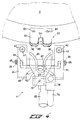
- Figs. 1 a and 1 b show a fixed cylindrical control element 2, along the cylindrical surface of which five scraper units 4 can move, through the fact that, on the one hand, the scraper units 4 are slidable in a vertical direction along guide rods 6 and, on the other, the guide rods 6 are connected to disc-shaped bearing plates 8 and 10, which can be rotated in a certain direction by means of a shaft 12 with the aid of a drive 14.
- the scraper units 4, which in this case are shown symbolically as rectangular blocks, are described in detail below with reference to Figs. 2 - 10.
- the control element 2 is provided on its cylindrical surface with guide grooves 16, 18 and 20 for moving each scraper unit 4 with the aid of guide means 17 along the guide rods 6 according to the course of the groove 16 on rotation of the bearing plates 8 and 10, and for controlling, with the aid of guide means 19 and 21, movements of parts of each scraper unit on rotation of the bearing plates 8 and 10.
- each scraper unit 4 Fitted above the top bearing plate 10 is a suspension disc 22 which rotates in synchronism with the bearing plates 8 and 10 and above each scraper unit 4 is provided with a slit-shaped recess 24, in which a leg 25 of a bird can hang by the tarsal joint.
- the width of the recess 24 is ample for the accommodation of the bone of the lower leg of the bird, but is narrower than the cross-section of the tarsal joint, as a result of which the leg is prevented from moving in the downward direction and in the tangential direction.
- the leg part near the tarsal joint is fed, on rotation of the suspension disc 22, between two guide rails 26 and 27 running above the disc in the tangential direction, which rails lie at a distance from each other which is approximately equal to the width of the recess 24.
- Rail 26 extends over a smaller angle than rail 27, which will be explained in the discussion of Figs. 5 - 11.
- the component parts of the scraper unit described above interact during the rotation of the shaft 12 in the direction of arrow 28 and the plates 8 and 10 coupled thereto in such a way that, after the hanging of a leg 25 in a recess 24 of the suspension disc 22, symbolically shown at the top side of Fig. 1 b , the thigh meat is scraped off the thigh bone of the leg 25 in a manner and with a device which will be described in greater detail below, following which the thigh meat 30 leaves the device at a particular point on the periphery, followed by the leg 32 from which the thigh meat 30 has been scraped off.
- Figs. 2, 3 and 4 show an embodiment of the scraper unit 4, the basic construction of which is formed by two essentially U-shaped carriers 34 which are connected to each other by connecting rods 36 and 38. The connection is secured by means of bolts 37.
- Through holes 40 with bearing bushes 42 are fitted in the two limbs of the two carriers 34, by means of which the carriers 34 can slide in a vertical direction over the rods 6, which are fixed by means of bolts 9 and 11 to bearing plates 8 and 10 respectively.
- This sliding movement is controlled by the groove 16 in the control element 2, in which groove 16 can run a wheel 44 which is mounted rotatably about a bolt 43 on a pin 46 fixed to connecting rod 36.
- the connection is secured by means of bolt 48.
- the scraper unit 4 further comprises a first scraper element 50 and a second scraper element 52, the movement of which is controlled by grooves 18 and 20 respectively in their relation to groove 16 in the control element 2, and is transmitted to the scraper elements 50 and 52 by means of wheel 54, levers 56 and 58 and coupling strip 60, and wheel 62 and lever 64 respectively.
- the wheel 54 is to this end fixed by means of bolt 55 to lever 56, which can pivot about a shaft 66 fitted in the carriers 34 by means of bolts 65.
- Lever 56 is connected at its end facing away from the wheel 54 by means of coupling strip 60 to the central part of lever 58, which can pivot about a shaft 70 fitted in the carriers 34 with the aid of bolts 68.
- the coupling strip 60 can pivot about two bolts 72 and 74 and transmits a movement of the lever 56 to the lever 58.
- transverse bar 76 Fitted at the end of lever 58 facing away from the shaft 70 is a transverse bar 76 which at its end bears in a holder 78 the first scraper element 50 with the aid of a bolt 79.
- the wheel 62 is fixed rotatably about bolt 63 on lever 64, which can pivot about the shaft 70.
- transverse bar 80 which bears at its end a fixing plug 82, on which the second scraper element 52 is fixed by means of two bolts 84.
- the first scraper element 50 is plate-shaped and bent along the arc of a circle with the centre point in the centre line of the shaft 70, and is provided with a recess which is open at one side and has an edge boundary 86, intended for scraping.
- the part of the edge boundary 86 which lies at the foot of the recess near bolt 79 is sharply ground and intended for cutting.
- the second scraper element 52 is plate-shaped and curved in the arc of a circle with the centre point on the centre line of the shaft 70, which arc has a smaller radius than the arc belonging to the first scraper element 50.
- the second scraper element 52 has a laminated structure and comprises two rigid plates 88 and 90, between which a plate 92 of flexible material is mounted. All three plates 88, 90 and 92 are provided with a recess which is open at the side facing the first scraper element 50.
- the width of the recess in the rigid plates 88 and 90 is in this case slightly greater than the width of the recess in the flexible plate 92, which means that only the flexible material comes into contact with the bone of the thigh to be scraped.
- the flexible plate 92 also has a stop 94 which borders on the end of the recess in the second scraper element 52.
- the two scraper elements 50 and 52 can, under the control of the grooves 18 and 20 in the control element 2, move away from and towards each other, in which latter movement the first scraper element 50 can slide over the second scraper element 52, as a result of which the above-mentioned recesses determine a scraper opening with at least approximately the cross-section of a thigh-bone if the scraper elements 50 and 52 are slid partially over each other.
- An essentially partially circular recessed part 87 is fitted in the edge boundary 86 of the first scraper element 50, as a result of which the scraper opening is enlarged at that side to allow a cartilage nodule on the hip joint to pass during the scraping.
- This cartilage nodule is found on the left side of the right leg of a bird and the right side of the left leg, and the first scraper element 50, which in the case shown is intended for processing right legs, therefore always has to be adapted to the case in question.
- a stop is fixed by means of bolts 95 in blind holes in the carriers 34, which stop comprises a bridge 96, a V-shaped push rod 98 fixed thereto, and an aligning plate 99.
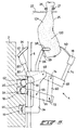
- Fig. 5 shows the scraper unit 4 in a low initial position, in which the first scraper element 50 and the second scraper element 52 are far apart in order to admit a bird leg 25 hanging from guide rails 26 and 27 between said elements 50 and 52.
- the leg 25 finally hangs with its front side against push rod 98, while turning of the leg relative to the suspension between guide rails 26 and 27 is prevented by means of aligning plate 99.
- Figs. 7 and 8 show that, starting from the position shown in fig. 6, the first scraper element 50 moves over the skin surface of the rear side of the thigh meat 100 in the direction of the knee joint of the leg.
- the leg 25 in the process comes to rest in the recess of the first scraper element 50, the wedge-shaped edge boundary 86 of the recess pushing the meat ahead of it at either side of the knee joint and thus, interacting with the push rod 98, bending the leg 25.
- Fig. 9 shows that the first scraper element 50 has been moved until it is above the push rod 98, in which case the sharply ground part of the recess of the first scraper element 50 has cut into the meat at either side of the knee joint, and the second scraper element 52 is brought into contact with the leg 25 which has been bent at approximately a right angle.
- a knife 101 which is disposed in a fixed manner relative to the control element 2, at this stage makes an incision at the rear side of the leg 25 in the back of the knee, which place in this phase of the processing is well-defined through the preceding movement of the first scraper element 50 and is reproducible, irrespective of the variable length within certain limits of a drumstick 104 of a leg.
- the second scraper element 52 then slides further below the first scraper element 50, in which case a scraper opening with a cross-section the size of the thigh-bone is produced.
- the scraper elements 50 and 52 thereafter move jointly to a predetermined position, shown in Fig. 10, in which the knee joint is stretched and the kneecap rests on the stop 94 of the second scraper element 52. During this movement the stop 94 presses the leg below the kneecap upwards relative to the guide rail 27. There is enough space for this because at that place guide rail 26 no longer runs above suspension disc 22.
- Fig. 11 shows the scraping off of the thigh meat 100 from the thigh-bone 106, by moving the scraper unit 4 from the position shown in Fig. 9 downwards, while maintaining the position of the scraper elements 50 and 52 slid over one another.
- the recessed part 87 of the first scraper element 50 ensures that the cartilage nodule on the hip joint is not mechanically stressed by the element 50, so that it cannot break off during the scraping.
- Fig. 12 shows, by way of example, a different embodiment of the scraper unit 4.
- an L-shaped bracket is added to said scraper unit and is rigidly fixed to a rod 57 which can pivot about shaft 68.
- the movement of the bracket 77 which is intended in conjunction with push rod 98 to bend the leg by pivoting anticlockwise about the shaft 68 according to the view of the drawing, takes place under the control of lever 53 which can pivot about shaft 66 if the roller 73 rotatably connected by means of bolt 75 to lever 53 moves upwards or downwards in groove 11 of control element 2.
- Lever 53 is connected to rod 57 by means of rod 61 so that it is pivotable about shafts 107 and 109.
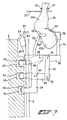
- Fig. 13 shows a part of a conveyor line in which a left leg 110 and a right leg 112, each of which is hung up by its tarsal joint, are moved along by means of a double hook 114 in a conveyor 116 in the direction of arrow 118.
- a pair of legs 110, 112 hanging in such a way is obtained, for example, by separating the body from the legs of a bird hanging by the tarsal joints and being moved with the breast in the direction of arrow 118 in the conveyor 116.
- the conveyor 116 in which many hooks are moved along, most of which for the sake of clarity are not shown, comprises three tracks 120, 122 and 124 over which the hook 114 moves, track 122 comprising a drive for the hook 114 and being uninterrupted.
- the track 120 along which the right leg 112 moves and the track 124 along which the left leg 110 moves are both interrupted, in which interruptions the same scraper units 126 and 128, respectively, as those shown in Fig. 1 b are placed.
- the suspension discs 127 and 129 of the scraper units 126 and 128 respectively rotate in opposite directions to each other, indicated by arrows 130 and 132 respectively.
- Guides 134 and 136 are fitted above the track and the suspension disc 127, near the interruption in the track 120; guides 138 and 140 are fitted in the same way above the track and the suspension disc 129, near the interruption in the track 124.
- the movements of the hook 114 and the suspension discs 127 and 129 are synchronized in such a way that on passing of the hook 114 guide 138 guides the left leg 110 from the hook into a slit of the suspension disc 129.
- guide 134 on passing of the hook 114 guides the right leg 112 from the hook into a slit of the suspension disc 127.
- the left leg 110 and right leg 112 are conveyed back by means of guides 140 and 136 respectively on the tracks 124 and 120 respectively into the recesses of a hook 114.
- guides 140 and 136 respectively on the tracks 124 and 120 respectively into the recesses of a hook 114.
- thigh meat with tendons can remain hanging on the hip joint part of the thigh-bone.
- the thigh meat must then be cut away from the thigh-bone using cutting means which are not shown. This can take place in the scraper units 126 and 128 or after rehanging of the legs in the conveyor 116.
- the legs which have had the thigh meat removed from them continue on their way in the conveyor 116, following which the thigh-bone is separated preferably automatically from the drumstick in a known manner.
- the thigh meat coming from the scraper units 126 and 128 is collected and discharged mechanically.
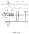
- the device for cutting off drumsticks comprises a frame 151, containing a conveyor 152, in this case an overhead runway, by means of which the legs 154 hanging by the tarsal joint 153 are brought in.
- the device is also provided with two movable elements 155 each disposed on either side of the conveyor 152.
- each movable element 155 is rotatably mounted on a shaft 156.
- Each element 155 is also provided with a number of (in this case five) radially directed fork-shaped carriers 157 which during operation run in a circular path virtually tangentially along the centre line 158 of the conveyor 152.
- the forward movement of the conveyor is shown by an arrow T in Fig.
- each element 155 with the carriers 157 moving in a direction R which is opposite to the direction of the conveyor 152.
- the purpose of each rotary element 155 is to take over one by one the legs 154 from the conveyor 152, to retain them and to return them, which have been cut through in the meantime.
- the device is also provided with a cutting element 159 interacting with each element 155 for cutting through the capsule, the ligaments and the tendons of the knee joint 160, and thus releasing the thigh 161 from the leg 154.
- a V-shaped supporting element 162 which moves along with the rotary element 155 and is also directed radially outwards, as can be seen in Fig. 14.
- a push rod 163 is fixed along a part of the circular path of the supporting elements 162. This part of the circular path is away from the conveyor 152, i.e. is situated diametrically relative to the part running along the centre line 158 of the conveyor 152.
- the purpose of each push rod 163 is to gradually exert pressure in the radial inward direction against the back of the knee of a leg 154 present in a carrier 157.
- a displaceable lifter 164 is fitted at each of the V-shaped supporting elements 162 for pressing upwards - i.e. in the direction of the tarsal joint 153 - the kneecap 165 of a leg joint 160 pressed by the rod 163 against the supporting element (see the situation indicated by a dashed and dotted line in Fig. 16).
- the supporting element 162 is made up of two scissor-shaped open limbs 166, 167.
- the upper limb 166 is provided with a thickened part 168 against which the leg 154 rests during bending of the knee joint 160.
- the lower limb 167 bears the displaceable lifter 164.
- a curved track 169 (see Fig. 18) is disposed concentrically with the shaft 156 of each rotary element 155.
- Each lifter 164 is rotatably fitted on the lower limb 167 of the supporting element 162 and is also provided with a radially inward-directed follow-on roller 170 which can interact with the curved track 169.
- One of the two limbs 166, 167 of the supporting element 162 is rotatable relative to the other limb.
- the lower limb 167 is rotatable relative to the fixed upper limb 166.
- this lower limb is provided with a radially inward directed follow-on roller 171. This roller can interact with a second concentrically disposed curved track 172 for temporarily snapping the supporting element 162 to a closed position.
- the above-mentioned cutting element 159 is formed by a disc 173 which is rotatable about a shaft 174 supported in the frame 151.
- the angular position of this shaft 174 is adjustable for altering or adjusting the position of the disc 173 relative to the supporting element 162.
- This is connected with the basic idea of the present proposal: cutting through the knee joint 160 at a predetermined place.
- Fig. 15 one of the two rotary elements 155 disposed at either side of the conveyor 152 is staggered relative to the other.
- Fig. 14 shows that each element 155 is provided with its own drive motor 175, the speed of rotation of which is synchronized with the forward movement speed of the conveyor 152, since each of the five carriers 157 must be able to interact with following bearing elements (not shown) of this conveyor.
- the device described above operates as follows.
- the conveyor 152 feeds in a regular stream of legs 154, both right and left of the centre line 158. This stream moves in the direction of the arrow T.
- each leg is removed from the conveyor 152 by means of guide elements 176, 177 and fed into a fork-shaped carrier 157 of the element 155 present on the spot at that moment.
- Said rotary element turns in a direction R opposite to the direction T of the conveyor 152 and carries the suspended leg 154 past the fixed push rod 163 situated some distance below the element 155, at the level of the V-shaped supporting element 162.
- the position of the push rod 163 can be seen clearly in Figs. 14 and 15. This push rod is used to exert a gradually increasing pressure in the radially inward direction against the back of the knee of the leg present in the carrier 157.
- Fig. 16 is gradually produced.
- the curved track 169 goes into operation, in which case the follow-on roller 170 of the lifter 164 is forced downwards.
- the point of the lifter 164 in this case lifts the kneecap 165 from the joint 160 and at the same time fixes the leg 154 in the supporting element 162.
- This fixing is further aided by the presence of a recess 178 next to the upper limb 166 of the supporting element 162.
- the fork-shaped carrier 157 with the leg 154 passes the cutting element 159, i.e. the disc 173.
- the knee joint 160 is cut through in this way.
- the thigh 161 falls down, and only the lower leg or drumstick remains behind with its tarsal joint 153 in the fork-shaped carrier 157 of the rotary element 155.
- the drumstick is fed back to the conveyor 152 by means of a second set of guide elements 179, 180.
- the lifter 164 also returns to its normal position.
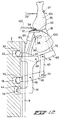
- Figs. 20 a , 20 b and 21 show a conveyor 190 by means of which bird legs 192 suspended by their tarsal joint can be conveyed at regularly spaced intervals along a guide rail 194 with transport elements 196 movable in the direction indicated with an arrow 198.
- a device according to the invention for cutting off drumsticks is disposed, the device in the shown embodiment comprising a elongated frame 200 composed mainly of beams and strips for supporting the remaining components of the device, a guide strip 202, two double gear wheels 204, 206 rotatably mounted in the frame 200 at different ends, an endless double chain 208 coupling the gear wheels 204, 206, leg positioning means 210 fitted to the double chain 208 at distances corresponding to the distances between transport elements 196 and movable therewith, and separating means 212 interacting with the guide strip 202 for separating the drumstick from the thigh of the leg 192.
- the gear wheel 204 can be driven by means of a shaft 214 in such a way that the double chain 208 moves in perfect synchronism with the transport elements 196, e.g. by coupling the shaft 214 through a suitable transmission (not shown) to the drive (not shown) of the transport elements 196.
- the leg positioning means 210 comprise two positioning blocks 216, 218 with a first stop surface 220 inclined at approximately 45° to a second horizontal stop surface 222, as can best be seen in fig. 21.
- the first positioning block 216 comprises an outward projecting aligning plate 224 at right angles with the stop surfaces 220, 222.
- the device shown in Fig. 20 a , 20 b and 21 is designed for processing only one kind of bird legs, e.g. right legs. Should both right legs and left legs be processed simultaneously, then the device can be doubled having mirror symmetry with reference to a plane indicated by line 223.
- Guide strip 202 has a gradually sideways widening run-in part 228 with a blunt guide edge 226, a gradually sideways narrowing run-out part 230, and an intermediate part 229 in which the blunt guide edge 226 is straight and runs parallel to the guide rail 194 (not shown here).
- the plate-shaped separating means 212 comprise a run-in part 232 with a cutting edge 234, a joint-separating part 236 with a blunt edge 238 and a drumstick cutting part 240 with a cutting edge 242, folded back at the end.
- the guide edge 226 at the intermediate part 229 of the guide strip 202 and the cutting edge 234 of the separating means 212 define a narrowing gap, as seen in the direction of arrow 198.
- the blunt guide edge 226 at the intermediate part 229 and the blunt edge 238 principally run parallel to each other.
- the straight blunt edge 226 at the intermediate part 229 and the straight cutting edge 242, as seen in the direction of arrow 198, converge and intersect, while after the intersection point the separating means extends under the guide strip 202.
- the operation of the linear drumstick cutting device is as follows.
- a leg 192 of a bird suspended by its tarsal joint is brought in by the transport element 196 moving along guide rail 194.
- leg positioning means 210 move beside (positioning blocks 216, 218) and behind (aligning plate 224) the leg, which is thereby rotated around its longitudinal axis until the kneecap of the knee joint is situated transversely to the direction of conveyance 198, pointing sideways in the direction of the separating means 212.
- the leg 192 is pushed out sideways in the back of the knee by the guide strip 202, after which, when entering the region of the run-in part 232 of the separating means 212 the cutting edge 234 cuts through the skin and the kneecap 250.
- the kneecap 250 is situated accurately in a predetermined position on the horizontal stop surface 222 of the positioning block 216, pushed over the edge between the first stop surface 220 and the second stop surface 222 by the force exerted by the blunt guide edge 226 of the guide strip 202 on the back of the knee.
- the blunt edge 238 of the separating means 212 is driven between the ends of the drumstick bone 252 and the thigh-bone 254, thus separating the knee joint without damaging the bone ends.
- the knee joint is further separated by the presence of a push element 256 exerting a downward force on the thigh bone 254. This in particular prevents a cartilage nodule 258 on the end of the thigh bone 254 from being damaged.
- Fig. 23 c illustrates the cutting off of a drumstick by moving the leg 192 further along the guide edge 226 of the guide strip 202 past the intersection point of the guide edge 226 and the cutting edge 242 of the separating means 212.
- the folded back end of the cutting edge 242 ensures that the thigh is completely separated from the lower leg, since any remaining connections between the two leg parts by the skin or the like are trapped and cut in the converging V-shaped region.
- the drumstick is conveyed further by means of the transport elements 196 of the conveyor 190 to a place where they are collected and packed.
- the thighs separated from the drumsticks are also collected and may be processed further by conventional deboning means.
Landscapes
- Life Sciences & Earth Sciences (AREA)
- Engineering & Computer Science (AREA)
- Food Science & Technology (AREA)
- Wood Science & Technology (AREA)
- Zoology (AREA)
- Processing Of Meat And Fish (AREA)
Claims (33)
- Procédé pour effectuer une opération de sectionnement sur une patte (25;154;192) d'un animal abattu, en particulier une volaille, dans ou à proximité immédiate de l'articulation du genou de la patte, dans lequel la patte est amenée en position par un moyen mécanique par rapport à un moyen de sectionnement pour effectuer l'opération de sectionnement, caractérisé en ce que, avant l'opération de sectionnement, un moyen de positionnement mécanique agit sur la rotule pour positionner l'articulation du genou par rapport au moyen de sectionnement.
- Procédé selon la revendication 1, caractérisé en ce que, avant ou pendant le positionnement de la rotule par rapport au moyen de sectionnement, la patte (25;154; 192) est fléchie dans sa direction de fléchissement naturelle au niveau de l'articulation du genou.
- Procédé selon la revendication 2, caractérisé en ce que la patte (25;154;192) est fléchie de telle manière que la partie de la patte située d'un côté de l'articulation du genou soit approximativement perpendiculaire à la partie de la patte située de l'autre côté de l'articulation du genou.
- Dispositif pour effectuer une opération de sectionnement sur une patte (25;154;192) d'un animal abattu, en particulier une volaille, dans ou à proximité immédiate de l'articulation du genou de la patte, le dispositif comprenant:
un moyen mécanique (26,27,162,196) pour manipuler la patte (25;154;192); et
un moyen de sectionnement (102,159,212) pour effectuer l'opération de sectionnement, caractérisé par un moyen de positionnement mécanique (50,52,94,163,164,202,222) conçu pour agir sur la rotule afin de positionner l'articulation du genou par rapport au moyen de sectionnement (102,159,212). - Dispositif selon la revendication 4, caractérisé par un moyen de flexion pour amener la patte (25;154;192) à fléchir dans sa direction de flexion naturelle au niveau de l'articulation du genou.
- Dispositif selon la revendication 5, caractérisé en ce que le moyen de flexion est conçu pour amener la patte (25;154;192) à fléchir de telle manière que la partie de la patte située d'un côté de l'articulation du genou soit approximativement perpendiculaire à la partie de la patte située de l'autre côté de l'articulation du genou.
- Dispositif selon l'une quelconque des revendications 4 à 6, caractérisé en ce que le moyen de positionnement comporte un ou plusieurs éléments de support (94;164;216,218) avec un bord d'arrêt, qui peuvent prendre différentes positions par rapport au moyen mécanique de manipulation de la patte (25;154;192), afin de pouvoir déplacer le bord d'arrêt le long de la cuisse de la patte jusqu'à une position contre la rotule.
- Dispositif selon l'une quelconque des revendications 4 à 7 pour enlever la chair (100) d'un fémur (106) d'animal abattu, en particulier une volaille, comportant un moyen racleur (50,52) pour racler la chair de cuisse sur le fémur depuis l'articulation du genou jusqu'à l'articulation de la hanche, caractérisé par un élément de suspension (22) pour suspendre par l'articulation de la cheville une patte (25) à traiter.
- Dispositif selon la revendication 8, caractérisé en ce que le moyen de sectionnement (86,101,102) peut réaliser une incision dans la chair sur au moins un des côtés de l'articulation du genou, sensiblement perpendiculairement au sens longitudinal de la patte (25), laquelle incision constitue le point de départ pour l'opération de raclage.
- Dispositif selon la revendication 8 ou 9, caractérisé en ce que le moyen de raclage comporte un premier et un second éléments racleurs incurvés (50,52) en forme de plaques, mobiles selon un arc de cercle, lesquels éléments racleurs peuvent coulisser l'un sur l'autre, peuvent tous deux être déplacés perpendiculairement à la surface de la plaque et comportent chacun au niveau de leur bord en regard l'un de l'autre un évidement ouvert d'un côté, ces deux évidements déterminant une ouverture de raclage ayant au moins la section transversale approximative d'un fémur si les éléments racleurs sont amenés à coulisser partiellement l'un sur l'autre.
- Dispositif selon la revendication 10, caractérisé en ce que le bord limite de l'évidement du premier élément racleur (50) dans la région déterminant l'ouverture de raclage comporte une partie évidée (87) globalement partiellement circulaire.
- Dispositif selon la revendication 10 ou 11, caractérisé en ce que le second élément racleur (52) comporte une pièce rapportée fixe (92) en matière élastique qui détermine l'évidement dudit élément racleur.
- Dispositif selon l'une quelconque des revendications 10 à 12, caractérisé en ce que, pendant l'opération de raclage, l'élément de suspension (22,27) englobe de tous côtés la patte (25) avec un jeu près de l'articulation de la cheville du côté de l'articulation du genou, l'ouverture de l'emprise étant inférieure à la section transversale de l'articulation de cheville.
- Dispositif selon l'une quelconque des revendications 10 à 13, caractérisé en ce que le moyen de sectionnement est formé par une combinaison des éléments sui-vants:
le premier élément racleur (50) dont le bord limite (86) du pied de l'évidement est affûté, afin de permettre un sectionnement sous la pression du second élément racleur (52) sur les côtés et sur la face arrière de l'articulation du genou; et
deux couteaux (101,102) qui circulent le long de l'articulation du genou, perpendiculairement au sens longitudinal de la patte (25) et qui peuvent couper respectivement sur les faces avant et arrière de l'articulation du genou. - Dispositif selon l'une quelconque des revendications 10 à 14, caractérisé en ce que le moyen de positionnement est formé par une combinaison des éléments suivants:
le second élément racleur (52) qui, dans la région déterminant l'ouverture de raclage, comporte une butée (94) servant à pousser la rotule vers le haut contre son bord; et
un moyen de commande pour commander les mouvements de flexion et les déplacements des moyens racleurs. - Dispositif selon l'une quelconque des revendications 10 à 15, caractérisé en ce que le moyen de flexion est formé par une combinaison des éléments suivants:
l'élément de suspension (22) pour suspendre la patte (25) par l'articulation de la cheville;
le premier élément racleur (50); et
une butée (98) pour retenir la cuisse au niveau de l'articulation de la hanche sur la face antérieure de la patte. - Dispositif selon l'une quelconque des revendications 10 à 15, caractérisé en ce que le moyen de flexion est formé par une combinaison des éléments suivants:
l'élément de suspension (22) pour suspendre la patte (25) par l'articulation de la cheville;
un support (77) dont une extrémité peut être déplacée à l'arrière du genou de la patte (25); et
une butée (98) pour retenir la cuisse sur la face avant de la patte au niveau de l'articulation de la hanche. - Dispositif selon la revendication 16 ou 17, caractérisé en ce que la butée (98) comporte une plaque d'alignement (99) pour empêcher la patte (25) de tourner autour de son axe.
- Dispositif selon l'une quelconque des revendications 10 à 18, caractérisé par une combinaison de différents dispositifs racleurs (4) mobiles autour d'un moyen de commande central.
- Dispositif selon l'une quelconque des revendications 15 à 19, caractérisé en ce que le moyen de commande comprend un élément de commande central sensiblement cylindrique (2) pourvu de rainures de guidage (11,16,18,20) sur la surface cylindrique, rainures de guidage dans lesquelles des éléments de commande (73,44, 54,62) des dispositifs racleurs (4) peuvent se déplacer, pour commander les organes des dispositifs racleurs.
- Dispositif selon la revendication 19 ou 20, caractérisé en ce que la combinaison de dispositifs racleurs (4) est logée dans une chaîne transporteuse (116) dans laquelle les pattes (25) suspendues à des crochets (114) sont acheminées, les pattes étant transférées depuis cette chaîne transporteuse jusqu'aux éléments de suspension (127,129) avant l'opération de raclage, et dans lequel les pattes sont à nouveau suspendues après l'opération de raclage.
- Dispositif selon l'une quelconque des revendications 4 à 7 pour sectionner l'articulation du genou d'une patte (154) d'animal abattu, en particulier une volaille, comportant un bâti (151) avec un transporteur (152) pour apporter les pattes suspendues par l'articulation de la cheville (153), caractérisé en ce que:- au moins un élément rotatif (155) est disposé à proximité du transporteur pour intercepter les pattes une par une sur le transporteur et les retenir, et pour restituer les parties inférieures de ces pattes, cet élément rotatif (155) étant pourvu d'un certain nombre de supports (157) qui, en fonctionnement, se déplacent sur un parcours circulaire d'une manière pratiquement tangentielle le long de l'axe central (158) du transporteur (152), dans une direction (R) opposée au mouvement d'avance (T) du transporteur, en passant devant un élément coupant (159) coopérant avec chaque élément rotatif (155);- un élément de support (162) en forme de V, qui dépasse radialement vers l'extérieur et qui se déplace en accompagnant l'élément rotatif (155) est présent sous chaque support (157);- un poussoir (163) est disposé le long d'une partie du parcours circulaire des éléments de support (162) à distance du transporteur (152), pour exercer progressivement une pression orientée radialement vers l'intérieur contre l'arrière du genou d'une patte présente dans un support (157);- un dispositif de levage mobile (164) est disposé au niveau de chacun des éléments de support (162) en forme de V pour positionner, dans la direction de l'articulation de la cheville, la rotule d'une articulation de genou poussée contre l'élément de support en question par le poussoir (163).
- Dispositif selon la revendication 22, caractérisé en ce que l'élément de support (162) est constitué par deux branches ouvertes (166,167), en forme de ciseaux, la branche supérieure (166) comportant une partie épaissie (168) contre laquelle la patte repose pendant la flexion de l'articulation du genou, la branche inférieure (167) portant le dispositif de levage mobile (164).
- Dispositif selon la revendication 22 ou 23, caractérisé en ce qu'une piste courbe (169) est disposée d'une manière concentrique à l'arbre (156) de chaque élément rotatif (155), et en ce que chaque dispositif de levage (164) est disposé d'une manière rotative sur la branche inférieure (167) de l'élément de support (162) et comporte en outre un galet suiveur (170) orienté radialement vers l'intérieur et apte à coopérer avec ladite piste incurvée (169).
- Dispositif selon la revendication 24, caractérisé en ce qu'une des deux branches (166,167) de l'élément de support (162) peut tourner par rapport à l'autre branche et comporte également un galet suiveur (171), orienté radialement vers l'intérieur, qui peut coopérer avec une seconde piste incurvée (172), disposée d'une manière concentrique, pour fermer temporairement l'élément de support (162).
- Dispositif selon l'une quelconque des revendications 22 à 25, dans lequel l'élément coupant est formé par un disque apte à tourner autour d'un arbre supporté dans le bâti, caractérisé en ce que la position angulaire de l'arbre (174) est réglable, pour adapter la position du disque (173) par rapport à l'élément de support (162).
- Dispositif selon l'une quelconque des revendications 22 à 26, caractérisé en ce qu'un élément rotatif (155) est disposé de part et d'autre du transporteur (152), et en ce que chaque élément comporte son propre moteur d'entraînement (175) dont la vitesse de rotation est synchronisée avec la vitesse de marche avant du transporteur (152).
- Dispositif selon l'une quelconque des revendications 4 à 7 pour sectionner l'articulation du genou d'une patte (192) d'animal abattu, en particulier une volaille, comportant un bâti (200) avec un transporteur (190) pour apporter les pattes suspendues par l'articulation de la cheville, caractérisé par:- un moyen de guidage (202) avec un bord de guidage (226) s'étendant globalement parallèlement au sens de transport (198) du transporteur (190) pour repousser la patte latéralement;- un moyen (210) de positionnement de patte situé à côté des pattes (192) suspendues au transporteur (190) et coopérant, en fonctionnement, avec le moyen de guidage pour positionner la rotule d'une articulation de genou contre un élément de support; et- un moyen de séparation (212) coopérant avec le moyen de guidage et le moyen de positionnement de patte pour séparer le bas de la patte de la cuisse.
- Dispositif selon la revendication 28, caractérisé en ce que le moyen (210) de positionnement de patte comporte un ou plusieurs supports (216,218) avec une première surface d'arrêt inclinée (220) contiguë à une seconde surface d'arrêt horizontale (222), la courbe d'intersection des deux surfaces d'arrêt définissant un bord d'arrêt pour positionner la rotule de l'articulation du genou par rapport au moyen de séparation.
- Dispositif selon la revendication 28 ou 29, caractérisé en ce que le moyen (210) de positionnement de patte comporte un moyen d'alignement (224) pour aligner la patte (192) dans un plan vertical avant et pendant le fonctionnement du moyen de séparation.
- Dispositif selon l'une quelconque des revendications 28 à 30, caractérisé en ce que le moyen de positionnement est fixé à un moyen de transport sans fin qui peut être actionné en synchronisme avec le transporteur (190).
- Dispositif selon l'une quelconque des revendications 28 à 31, caractérisé en ce que le moyen de séparation (212) comporte une partie d'interception (232) avec une arête coupante (234) menant vers le bord de guidage (226) du moyen de guidage (202), une partie (236) de séparation d'articulation avec un bord (238) à arête arrondie s'étendant parallèlement au bord de guidage du moyen de guidage, et une partie (240) de sectionnement de pilon avec une arête coupante (242), menant vers et sous le bord de guidage du moyen de guidage.
- Dispositif selon la revendication 32, caractérisé en ce que l'extrémité de l'arête coupante (242) de la partie (240) de sectionnement de pilon du moyen de séparation (212) est rabattue vers l'arrière pour séparer complètement la cuisse du bas de la patte.
Applications Claiming Priority (4)
| Application Number | Priority Date | Filing Date | Title |
|---|---|---|---|
| NL9000228A NL9000228A (nl) | 1990-01-30 | 1990-01-30 | Werkwijze en inrichting voor het verwijderen van het vlees van een dijbeen van een geslachte vogel. |
| NL9000228 | 1990-01-30 | ||
| NL9002470A NL9002470A (nl) | 1990-11-12 | 1990-11-12 | Werkwijze en inrichting voor het lossnijden van een zgn. drumstick. |
| NL9002470 | 1990-11-12 |
Publications (2)
| Publication Number | Publication Date |
|---|---|
| EP0442554A1 EP0442554A1 (fr) | 1991-08-21 |
| EP0442554B1 true EP0442554B1 (fr) | 1994-01-05 |
Family
ID=26646651
Family Applications (1)
| Application Number | Title | Priority Date | Filing Date |
|---|---|---|---|
| EP91200165A Expired - Lifetime EP0442554B1 (fr) | 1990-01-30 | 1991-01-28 | Procédé et dispositif pour effectuer une opération de coupe précise près de l'articulation du genou d'une patte d'un animal abattu |
Country Status (6)
| Country | Link |
|---|---|
| US (1) | US5173077A (fr) |
| EP (1) | EP0442554B1 (fr) |
| JP (2) | JPH04211323A (fr) |
| DE (1) | DE69100902T2 (fr) |
| DK (1) | DK0442554T3 (fr) |
| ES (1) | ES2049076T3 (fr) |
Cited By (4)
| Publication number | Priority date | Publication date | Assignee | Title |
|---|---|---|---|---|
| CN111728013A (zh) * | 2019-03-25 | 2020-10-02 | 迈恩食品加工技术私人有限责任公司 | 从家禽的腿上获取鸡腿的方法和装置 |
| EP3745868A1 (fr) * | 2018-01-30 | 2020-12-09 | Foodmate US, Inc. | Procédé et appareil automatisés destinés à séparer des pattes de volaille en cuisses et pilons |
| US12070040B2 (en) | 2020-08-31 | 2024-08-27 | Marel Meat B.V. | Method and system for deboning of a carcass leg part of a four-legged slaughter animal, for removing meat from a bone of the carcass leg part |
| EP4595759A1 (fr) * | 2024-01-26 | 2025-08-06 | Ifec B.V. | Dispositif et procédé de traitement de parties de volaille ayant au moins un os |
Families Citing this family (44)
| Publication number | Priority date | Publication date | Assignee | Title |
|---|---|---|---|---|
| WO1992001385A1 (fr) * | 1990-07-23 | 1992-02-06 | Commonwealth Scientific & Industrial Research Organisation | Procede et appareil permettant de decouper des carcasses |
| NL9101050A (nl) * | 1991-06-18 | 1993-01-18 | Stork Pmt | Werkwijze en inrichting voor het bewerken van de huid van een poot van een geslachte vogel. |
| JPH0779609B2 (ja) * | 1992-10-28 | 1995-08-30 | ゴーデックス株式会社 | 食鳥の骨付もも肉の骨抜き装置 |
| DE4421882C2 (de) * | 1994-05-26 | 1997-02-06 | Nordischer Maschinenbau | Verfahren und Einrichtung zum Lösen des Fleisches von den Knochen tierischer Extremitäten |
| NL9400954A (nl) * | 1994-06-13 | 1996-01-02 | Stork Protecon Langen Bv | Inrichting voor het ontbenen van vleesstukken met een samengesteld beenstelsel. |
| NL1001226C2 (nl) * | 1995-09-18 | 1997-03-20 | Stork Pmt | Werkwijze en inrichting voor het ontbenen van een poot. |
| EP0858740B1 (fr) * | 1997-02-12 | 2001-11-07 | Nordischer Maschinenbau Rud. Baader Gmbh + Co Kg | Dispositif pour le traitement des pattes de volailles abattues |
| US7004830B2 (en) * | 1998-07-16 | 2006-02-28 | Stork Pmt B.V. | Method and device for processing poultry |
| WO2000035293A1 (fr) * | 1998-12-14 | 2000-06-22 | Athol Terence Sclanders | Desosseuse |
| NL1012703C2 (nl) * | 1999-04-06 | 2000-10-09 | Stork Pmt | Werkwijze en inrichting voor het bewerken van een gevogeltepoot. |
| US6354933B1 (en) * | 2000-05-01 | 2002-03-12 | Centre De Recherche Industrielle Du Quebec | Meat deboning apparatus and method |
| NL1025657C2 (nl) * | 2004-03-08 | 2005-09-12 | Meyn Food Proc Technology Bv | Inrichting voor het van elkaar scheiden van een drumstick en een dij. |
| NL1030388C2 (nl) * | 2005-11-10 | 2007-05-16 | Systemate Group Bv | Ontbener. |
| US8157625B2 (en) | 2010-01-26 | 2012-04-17 | Foodmate Bv | Method and apparatus for collecting meat from an animal part |
| US8632380B2 (en) | 2010-01-26 | 2014-01-21 | Foodmate B.V. | Method and apparatus for removing a sleeve of meat from an animal part having bone with knuckles on each of its opposite ends |
| JP5466541B2 (ja) * | 2010-03-11 | 2014-04-09 | 日本フードパッカー株式会社 | 棘突起分離装置 |
| NL2006075C2 (en) | 2011-01-26 | 2012-07-30 | Foodmate B V | Rotationally indexed article support for a conveyor system having an alignment station. |
| US8757354B2 (en) | 2010-04-19 | 2014-06-24 | Foodmate Bv | Turning block alignment |
| US8789684B2 (en) | 2010-04-19 | 2014-07-29 | Foodmate Bv | Rotatable article support for a conveyor |
| NL2004574C2 (en) | 2010-04-19 | 2011-10-20 | Foodmate B V | Rotatable article support for a conveyor. |
| US8727839B2 (en) | 2011-01-21 | 2014-05-20 | Foodmate Bv | Poultry wing cutter for narrow pitch poultry lines |
| US8882571B2 (en) | 2011-01-26 | 2014-11-11 | Foodmate Bv | Method of deboning animal thighs for separating and collecting meat therefrom and apparatus for performing the method |
| EP2667728B1 (fr) | 2011-01-26 | 2015-07-29 | Foodmate B.V. | Procédé de désossage de cuisses d'animaux pour en séparer et en recueillir la viande et appareil pour mettre en oeuvre le procédé |
| US8267241B2 (en) | 2011-01-26 | 2012-09-18 | Foodmate Bv | Rotationally indexed article support for a conveyor system having an alignment station |
| US8430728B2 (en) | 2011-02-14 | 2013-04-30 | Foodmate Bv | Special cut poultry wing cutter |
| JP5963556B2 (ja) * | 2012-06-14 | 2016-08-03 | 株式会社前川製作所 | 骨付きモモ肉の脱骨装置及び脱骨方法 |
| NL2009033C2 (en) | 2012-06-19 | 2013-12-23 | Foodmate B V | Weighing method and apparatus. |
| WO2014026695A1 (fr) * | 2012-08-17 | 2014-02-20 | Linco Food Systems A/S | Méthode de suspension d'un oiseau par un étrier et appareil de suspension d'oiseaux |
| US8808068B2 (en) | 2012-10-29 | 2014-08-19 | Foodmate Bv | Method of and system for automatically removing meat from an animal extremity |
| NL2009718C2 (en) | 2012-10-29 | 2014-05-01 | Foodmate B V | Method of mechanically removing skin from animal parts. |
| US9078453B2 (en) | 2013-11-01 | 2015-07-14 | Foodmate B.V. | Method and system for automatically deboning poultry breast caps containing meat and a skeletal structure to obtain breast fillets therefrom |
| EP3099179B1 (fr) * | 2014-01-28 | 2018-08-29 | Foodmate B.V. | Procédé et appareil de mesure de produits de viande se déplaçant séquentiellement le long d'une ligne de transformation de viande |
| CA2938143C (fr) * | 2014-02-07 | 2018-07-24 | Linco Food Systems A/S | Dispositif de positionnement destine a positionner des pattes de volailles transportees en une file dans le sens du transport le long d'une voie de transport, ainsi que procede co mportant le positionnement, pour enlever la chair des cuisses de pattes de volailles |
| US9326527B2 (en) | 2014-03-06 | 2016-05-03 | Mayekawa Mfg. Co., Ltd. | Device and method for deboning bone-in leg |
| NL2013019B1 (en) * | 2014-06-18 | 2016-07-05 | Marel Stork Poultry Proc Bv | Method and system for processing a defeathered whole leg poultry product. |
| NL2013017B1 (en) * | 2014-06-18 | 2016-07-05 | Marel Stork Poultry Proc Bv | Method and system for harvesting knee meat together with thigh meat from a poultry leg. |
| US9872506B2 (en) * | 2014-06-18 | 2018-01-23 | Marel Stork Poultry Processing B.V. | System and method for removing a thigh bone from a defeathered whole leg poultry product |
| NL2014197B1 (en) * | 2015-01-27 | 2017-01-06 | Foodmate Bv | Device for making a preparatory incision longitudinally of an animal extremity part with first and second bones articulated by a joint. |
| DK3603404T3 (da) * | 2017-12-25 | 2022-04-04 | Maekawa Seisakusho Kk | System til bearbejdning af ikke-udbenet kød og fremgangsmåde til fremstilling af adskilt kød |
| JP7129173B2 (ja) * | 2018-02-14 | 2022-09-01 | 株式会社前川製作所 | 骨付き肢肉の骨肉分離装置及び骨付き肢肉の骨肉分離方法 |
| NL2022799B1 (en) * | 2019-03-25 | 2020-10-02 | Meyn Food Processing Tech Bv | Apparatus and method for harvesting meat from poultry thighs |
| KR102350859B1 (ko) * | 2019-09-23 | 2022-01-13 | 지대호 | 닭고기 자동 절단장치 |
| BR112022017683A2 (pt) | 2020-03-04 | 2022-11-16 | Foodmate Us Llc | Método e aparelho para remover pele de partes animais |
| NL2027999B1 (en) * | 2021-04-16 | 2022-10-31 | Meyn Food Processing Tech Bv | Deboner for poultry parts |
Family Cites Families (24)
| Publication number | Priority date | Publication date | Assignee | Title |
|---|---|---|---|---|
| US2846718A (en) * | 1955-06-27 | 1958-08-12 | Swift & Co | Apparatus for cutting up poultry |
| US3038197A (en) * | 1959-03-19 | 1962-06-12 | King Mfg Corp | Disjointing machine for carcass limbs |
| US3199143A (en) * | 1962-10-22 | 1965-08-10 | James P Ousley | Apparatus for automatically severing the inedible portion of poultry legs |
| US3261054A (en) * | 1964-03-19 | 1966-07-19 | Campbell Soup Co | Automatic leg boning machine and system |
| US3323164A (en) * | 1964-07-27 | 1967-06-06 | Johnson Co Gordon | Separation of poultry shanks from drumsticks |
| US3364515A (en) * | 1965-04-12 | 1968-01-23 | Gainesville Machine Company In | Device for separation of jointed animal members |
| GB1188380A (en) * | 1966-10-17 | 1970-04-15 | Internat Agri Systems Inc | Apparatus for Severing the Hocks from Poultry Carcasses |
| GB1181462A (en) * | 1968-01-02 | 1970-02-18 | Gainesville Machine Company In | Device for Separation of Jointed Animal Members |
| NL165361C (nl) * | 1968-04-10 | 1981-04-15 | Prince Manufacturing Co | Inrichting voor het verwijderen van een bot uit een stuk vlees. |
| US3672000A (en) * | 1970-08-31 | 1972-06-27 | Victor F Weaver Inc | Machine to de-bone chicken thighs |
| US3643293A (en) * | 1970-10-13 | 1972-02-22 | Pillsbury Co | Poultry transfer apparatus and method |
| US4041572A (en) * | 1976-09-27 | 1977-08-16 | Victor F. Weaver, Inc. | Anatomical section de-boning machine |
| US4327463A (en) * | 1980-10-10 | 1982-05-04 | Victor F. Weaver, Inc. | Single station anatomical section de-boning machine |
| US4495675A (en) * | 1982-04-12 | 1985-01-29 | Hill Carl J | Method and apparatus for removing meat from the knuckled end of a bone |
| US4480353A (en) * | 1983-03-28 | 1984-11-06 | Foodcraft Equipment Co., Inc. | Leg splitting machine |
| NL186429C (nl) * | 1983-11-29 | 1990-12-03 | Maekawa Seisakusho Kk | Inrichting voor het verwijderen van vlees van gewrichten omvattende benen van gevogelte. |
| CA1203654A (fr) * | 1983-12-19 | 1986-04-29 | Stefan Pagowski | Machine-transfert de volailles |
| NL8401125A (nl) * | 1984-04-09 | 1985-11-01 | Stork Pmt | Werkwijze en inrichting voor het afscheiden van een lichaamsdeel voor geslacht gevogelte. |
| NL8401123A (nl) * | 1984-04-09 | 1985-11-01 | Stork Pmt | Drumsticksnijder. |
| NL8700213A (nl) * | 1987-01-28 | 1988-08-16 | Meyn Maschf | Inrichting voor het scheiden van het bot en het vlees van de poten van gevogelte of een gedeelte daarvan. |
| DE3743541A1 (de) * | 1987-12-22 | 1989-07-06 | Nordischer Maschinenbau | Einrichtung zum abstreifen des fleisches von den extremitaeten von gefluegel |
| US4893378A (en) * | 1988-10-31 | 1990-01-16 | Systemate Holland B.V. | Revoving poultry thigh deboner |
| US4896399A (en) * | 1989-01-31 | 1990-01-30 | Hazenbroek Jacobus E | Adjustable poultry carcass separator |
| US4964194A (en) * | 1989-04-24 | 1990-10-23 | L. J. Kessler | Apparatus and method for disjointing the thighbones of poultry carcasses |
-
1991
- 1991-01-28 DE DE91200165T patent/DE69100902T2/de not_active Expired - Fee Related
- 1991-01-28 EP EP91200165A patent/EP0442554B1/fr not_active Expired - Lifetime
- 1991-01-28 ES ES91200165T patent/ES2049076T3/es not_active Expired - Lifetime
- 1991-01-28 DK DK91200165.8T patent/DK0442554T3/da active
- 1991-01-29 US US07/647,580 patent/US5173077A/en not_active Expired - Lifetime
- 1991-01-30 JP JP3029329A patent/JPH04211323A/ja active Pending
-
2001
- 2001-10-03 JP JP2001307153A patent/JP2002171899A/ja active Pending
Cited By (6)
| Publication number | Priority date | Publication date | Assignee | Title |
|---|---|---|---|---|
| EP3745868A1 (fr) * | 2018-01-30 | 2020-12-09 | Foodmate US, Inc. | Procédé et appareil automatisés destinés à séparer des pattes de volaille en cuisses et pilons |
| CN111728013A (zh) * | 2019-03-25 | 2020-10-02 | 迈恩食品加工技术私人有限责任公司 | 从家禽的腿上获取鸡腿的方法和装置 |
| CN111728013B (zh) * | 2019-03-25 | 2022-02-22 | 迈恩食品加工技术私人有限责任公司 | 从家禽的腿上获取鸡腿的方法和装置 |
| US12070040B2 (en) | 2020-08-31 | 2024-08-27 | Marel Meat B.V. | Method and system for deboning of a carcass leg part of a four-legged slaughter animal, for removing meat from a bone of the carcass leg part |
| EP4595759A1 (fr) * | 2024-01-26 | 2025-08-06 | Ifec B.V. | Dispositif et procédé de traitement de parties de volaille ayant au moins un os |
| NL2036903B1 (en) * | 2024-01-26 | 2025-08-08 | Ifec B V | Device and method for processing poultry parts having at least one bone |
Also Published As
| Publication number | Publication date |
|---|---|
| ES2049076T3 (es) | 1994-04-01 |
| DK0442554T3 (da) | 1994-02-21 |
| JPH04211323A (ja) | 1992-08-03 |
| US5173077A (en) | 1992-12-22 |
| DE69100902T2 (de) | 1994-05-11 |
| JP2002171899A (ja) | 2002-06-18 |
| DE69100902D1 (de) | 1994-02-17 |
| EP0442554A1 (fr) | 1991-08-21 |
Similar Documents
| Publication | Publication Date | Title |
|---|---|---|
| EP0442554B1 (fr) | Procédé et dispositif pour effectuer une opération de coupe précise près de l'articulation du genou d'une patte d'un animal abattu | |
| US5833527A (en) | Poultry breast filleting apparatus | |
| US4993113A (en) | On-line thigh deboner | |
| EP1164857B1 (fr) | Procede et dispositif permettant de traiter une cuisse de poulet | |
| US4896399A (en) | Adjustable poultry carcass separator | |
| EP1346639B1 (fr) | Procédé pour le filetage de volailles abattues | |
| US4597136A (en) | On-line wing removal system | |
| US5035673A (en) | On-line breast halver | |
| US4993115A (en) | Compact wing cut-off machine | |
| CN106604642B (zh) | 用于从家禽腿采集膝肉连同大腿肉的方法和系统 | |
| EP0786206B1 (fr) | Dispositif pour enlever la viande des cuisses de volailles | |
| CN106163288B (zh) | 定位装置和从在输送方向上成排输送的家禽腿上移除大腿肉的方法 | |
| US20080171506A1 (en) | Processing of Carcass Parts of Slaughtered Poultry | |
| KR102166227B1 (ko) | 동물 사지로부터 고기를 자동으로 제거하기 위한 방법 및 시스템 | |
| US6027404A (en) | Poultry thigh deboner with movable stripper | |
| EP1639898A1 (fr) | Procede pour separer le sot-l'y-laisse de la cuisse et dispositif utilise a cet effet | |
| US5176562A (en) | Dark meat deboner with leg scraper | |
| EP1096860B1 (fr) | Procede et dispositif de traitement de volailles | |
| US7004830B2 (en) | Method and device for processing poultry | |
| JPH02177849A (ja) | 回転式鶏腿などの骨除去方法及び装置 | |
| EP0369544B1 (fr) | Dispositif pour séparer de la région dorsale les pattes de volailles abattues |
Legal Events
| Date | Code | Title | Description |
|---|---|---|---|
| PUAI | Public reference made under article 153(3) epc to a published international application that has entered the european phase |
Free format text: ORIGINAL CODE: 0009012 |
|
| AK | Designated contracting states |
Kind code of ref document: A1 Designated state(s): DE DK ES FR GB IT NL |
|
| 17P | Request for examination filed |
Effective date: 19910903 |
|
| 17Q | First examination report despatched |
Effective date: 19920729 |
|
| GRAA | (expected) grant |
Free format text: ORIGINAL CODE: 0009210 |
|
| AK | Designated contracting states |
Kind code of ref document: B1 Designated state(s): DE DK ES FR GB IT NL |
|
| ITF | It: translation for a ep patent filed | ||
| REF | Corresponds to: |
Ref document number: 69100902 Country of ref document: DE Date of ref document: 19940217 |
|
| REG | Reference to a national code |
Ref country code: DK Ref legal event code: T3 |
|
| ET | Fr: translation filed | ||
| REG | Reference to a national code |
Ref country code: ES Ref legal event code: FG2A Ref document number: 2049076 Country of ref document: ES Kind code of ref document: T3 |
|
| PLBE | No opposition filed within time limit |
Free format text: ORIGINAL CODE: 0009261 |
|
| STAA | Information on the status of an ep patent application or granted ep patent |
Free format text: STATUS: NO OPPOSITION FILED WITHIN TIME LIMIT |
|
| 26N | No opposition filed | ||
| PGFP | Annual fee paid to national office [announced via postgrant information from national office to epo] |
Ref country code: GB Payment date: 19950110 Year of fee payment: 5 |
|
| PGFP | Annual fee paid to national office [announced via postgrant information from national office to epo] |
Ref country code: ES Payment date: 19950130 Year of fee payment: 5 |
|
| PG25 | Lapsed in a contracting state [announced via postgrant information from national office to epo] |
Ref country code: GB Effective date: 19960128 |
|
| PG25 | Lapsed in a contracting state [announced via postgrant information from national office to epo] |
Ref country code: ES Free format text: LAPSE BECAUSE OF NON-PAYMENT OF DUE FEES Effective date: 19960129 |
|
| GBPC | Gb: european patent ceased through non-payment of renewal fee |
Effective date: 19960128 |
|
| REG | Reference to a national code |
Ref country code: ES Ref legal event code: FD2A Effective date: 19990503 |
|
| PG25 | Lapsed in a contracting state [announced via postgrant information from national office to epo] |
Ref country code: IT Free format text: LAPSE BECAUSE OF NON-PAYMENT OF DUE FEES;WARNING: LAPSES OF ITALIAN PATENTS WITH EFFECTIVE DATE BEFORE 2007 MAY HAVE OCCURRED AT ANY TIME BEFORE 2007. THE CORRECT EFFECTIVE DATE MAY BE DIFFERENT FROM THE ONE RECORDED. Effective date: 20050128 |
|
| PGFP | Annual fee paid to national office [announced via postgrant information from national office to epo] |
Ref country code: FR Payment date: 20060126 Year of fee payment: 16 |
|
| REG | Reference to a national code |
Ref country code: FR Ref legal event code: ST Effective date: 20070930 |
|
| PG25 | Lapsed in a contracting state [announced via postgrant information from national office to epo] |
Ref country code: FR Free format text: LAPSE BECAUSE OF NON-PAYMENT OF DUE FEES Effective date: 20070131 |
|
| PGFP | Annual fee paid to national office [announced via postgrant information from national office to epo] |
Ref country code: DK Payment date: 20090127 Year of fee payment: 19 |
|
| PGFP | Annual fee paid to national office [announced via postgrant information from national office to epo] |
Ref country code: NL Payment date: 20090131 Year of fee payment: 19 Ref country code: DE Payment date: 20090126 Year of fee payment: 19 |
|
| REG | Reference to a national code |
Ref country code: NL Ref legal event code: V1 Effective date: 20100801 |
|
| REG | Reference to a national code |
Ref country code: DK Ref legal event code: EBP |
|
| PG25 | Lapsed in a contracting state [announced via postgrant information from national office to epo] |
Ref country code: NL Free format text: LAPSE BECAUSE OF NON-PAYMENT OF DUE FEES Effective date: 20100801 |
|
| PG25 | Lapsed in a contracting state [announced via postgrant information from national office to epo] |
Ref country code: DE Free format text: LAPSE BECAUSE OF NON-PAYMENT OF DUE FEES Effective date: 20100803 |
|
| PG25 | Lapsed in a contracting state [announced via postgrant information from national office to epo] |
Ref country code: DK Free format text: LAPSE BECAUSE OF NON-PAYMENT OF DUE FEES Effective date: 20100131 |