EP0442692A1 - Stabilisateur de couture pour couvertures de corps en mousse - Google Patents
Stabilisateur de couture pour couvertures de corps en mousse Download PDFInfo
- Publication number
- EP0442692A1 EP0442692A1 EP91301099A EP91301099A EP0442692A1 EP 0442692 A1 EP0442692 A1 EP 0442692A1 EP 91301099 A EP91301099 A EP 91301099A EP 91301099 A EP91301099 A EP 91301099A EP 0442692 A1 EP0442692 A1 EP 0442692A1
- Authority
- EP
- European Patent Office
- Prior art keywords
- cover
- welt
- members
- component
- foam
- Prior art date
- Legal status (The legal status is an assumption and is not a legal conclusion. Google has not performed a legal analysis and makes no representation as to the accuracy of the status listed.)
- Granted
Links
- 239000006260 foam Substances 0.000 title claims abstract description 40
- 239000003381 stabilizer Substances 0.000 title abstract description 7
- 238000000034 method Methods 0.000 claims abstract description 18
- 238000000465 moulding Methods 0.000 claims abstract description 4
- 239000000463 material Substances 0.000 claims description 16
- 208000024780 Urticaria Diseases 0.000 claims description 13
- 238000005187 foaming Methods 0.000 claims description 6
- 238000004519 manufacturing process Methods 0.000 claims description 5
- 230000002093 peripheral effect Effects 0.000 claims description 5
- 238000009958 sewing Methods 0.000 claims description 2
- 239000007788 liquid Substances 0.000 claims 2
- 230000000295 complement effect Effects 0.000 claims 1
- 239000002131 composite material Substances 0.000 claims 1
- 230000000717 retained effect Effects 0.000 claims 1
- 238000007493 shaping process Methods 0.000 claims 1
- 230000037303 wrinkles Effects 0.000 abstract 1
- 239000008258 liquid foam Substances 0.000 description 3
- 230000000087 stabilizing effect Effects 0.000 description 3
- 239000006261 foam material Substances 0.000 description 2
- 230000000712 assembly Effects 0.000 description 1
- 238000000429 assembly Methods 0.000 description 1
- 239000003086 colorant Substances 0.000 description 1
- 239000004744 fabric Substances 0.000 description 1
- 238000002347 injection Methods 0.000 description 1
- 239000007924 injection Substances 0.000 description 1
- 238000000275 quality assurance Methods 0.000 description 1
- 210000000689 upper leg Anatomy 0.000 description 1
- 230000000007 visual effect Effects 0.000 description 1
Images


Classifications
-
- A—HUMAN NECESSITIES
- A47—FURNITURE; DOMESTIC ARTICLES OR APPLIANCES; COFFEE MILLS; SPICE MILLS; SUCTION CLEANERS IN GENERAL
- A47C—CHAIRS; SOFAS; BEDS
- A47C7/00—Parts, details, or accessories of chairs or stools
- A47C7/02—Seat parts
- A47C7/18—Seat parts having foamed material included in cushioning part
-
- B—PERFORMING OPERATIONS; TRANSPORTING
- B29—WORKING OF PLASTICS; WORKING OF SUBSTANCES IN A PLASTIC STATE IN GENERAL
- B29C—SHAPING OR JOINING OF PLASTICS; SHAPING OF MATERIAL IN A PLASTIC STATE, NOT OTHERWISE PROVIDED FOR; AFTER-TREATMENT OF THE SHAPED PRODUCTS, e.g. REPAIRING
- B29C44/00—Shaping by internal pressure generated in the material, e.g. swelling or foaming ; Producing porous or cellular expanded plastics articles
- B29C44/02—Shaping by internal pressure generated in the material, e.g. swelling or foaming ; Producing porous or cellular expanded plastics articles for articles of definite length, i.e. discrete articles
- B29C44/12—Incorporating or moulding on preformed parts, e.g. inserts or reinforcements
- B29C44/14—Incorporating or moulding on preformed parts, e.g. inserts or reinforcements the preformed part being a lining
- B29C44/143—Means for positioning the lining in the mould
-
- B—PERFORMING OPERATIONS; TRANSPORTING
- B68—SADDLERY; UPHOLSTERY
- B68G—METHODS, EQUIPMENT, OR MACHINES FOR USE IN UPHOLSTERING; UPHOLSTERY NOT OTHERWISE PROVIDED FOR
- B68G7/00—Making upholstery
-
- Y—GENERAL TAGGING OF NEW TECHNOLOGICAL DEVELOPMENTS; GENERAL TAGGING OF CROSS-SECTIONAL TECHNOLOGIES SPANNING OVER SEVERAL SECTIONS OF THE IPC; TECHNICAL SUBJECTS COVERED BY FORMER USPC CROSS-REFERENCE ART COLLECTIONS [XRACs] AND DIGESTS
- Y10—TECHNICAL SUBJECTS COVERED BY FORMER USPC
- Y10T—TECHNICAL SUBJECTS COVERED BY FORMER US CLASSIFICATION
- Y10T29/00—Metal working
- Y10T29/48—Upholstered article making
- Y10T29/481—Method
Definitions
- This invention relates generally to covers for foam parts of vehicle seat assemblies, such as the seat members and headrests, and more particularly to such foam parts which are improved from the standpoints of comfort and appearance by virtue of the use of the seam stabilizers of this invention in the covers for these parts.
- Such seat members are desirably formed with an interior load support section bounded by peripheral sections that function as bolsters to impart a feeling of stability and comfort to the occupant of the seat.
- the interior sections should further include a contoured surface to enhance the seat cushion's appearance and occupant's comfort.
- the present invention utilizes separate covering members to cover the interior section and the peripheral sections of the seat member.
- the separate covering members are secured in place by the attachment of these members to a tear away welt, or trim strip, which is integrated into a seam at the juncture of the sections, thereby stabilizing the seam and preventing wrinkling of the cover during the pour-in-place molding process of the foam pad.
- the above mentioned patent teaches the use of the welt to position the covering material on a mold and subsequently on a pre-shaped pad.
- the welt is not secured to the mold and a pre-shaped foam pad is not required. Rather, a pour-in-place process is used to form the foam pad.
- a pour-in-place process is used to form the foam pad.
- the overall production cost is lower since the step of attaching the foam pad to the cover is eliminated.
- the difficulties associated with aligning a pre-shaped pad with a shaped cover are nonexistent in the pour-in-place process, thereby resulting in a better fitting cover and a faster production process.
- the tear away welt of this invention is preferably molded of bendable plastic material, however, other materials providing sufficient rigidity may also be used. Initially, the welt is sewn into the covering members at their junctures, so as to stabilize the resulting seams and insure that the seam will maintain the desired shapes. A first mold member supports the covering members, and the welt, prior to molding of the foam pad. A second mold member is then positioned above the first mold member and a liquid foam material is injected into the mold cavity onto the cover members to form the foam pad to the cover assembly.
- the tear away welt provides accurate location of the covering members in the mold during the injection of the liquid foam material and also prevents the seams from moving and being out of alignment.
- the above mentioned welt has an annular body, positioned outside the seat component during assembly, and a notched tab portion, remaining within the seat component after assembly. At the juncture of the notched tab portion with the annular body, the welt is tapered to a reduced thickness to facilitate sewing and tearing.
- the covering members become adhered to the foam pad.
- the covering members and foam pad are then removed from the mold and the annular body portion of the tear away welt strip may be removed, if desired, by tearing it away from the notched tab portion.
- the result is a vehicle seat component in which the covering members are tightly adhered to the foam pad and conformed to the surface irregularities and designs of the foam pad.
- the interior and peripheral covering members can be formed of contrasting materials since different covering members are used in covering foam parts with this invention.
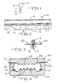
- the tear away welt of the claimed invention is shown in Figures 1 and 2 and generally designated 10.
- the welt 10 has an elongated annular body portion 12 connected to an elongated tab portion 14 through a tapered portion 16 and a neck portion 17.
- the tapered portion 16 and neck portion 17 allow seat cover portions 20 to be secured together and the annular body 12 to be removed from the tab portion 14 during final assembly, as discussed in detail below.
- the tab portion 14 also has notched portions 18 to increase flexibility of the welt 10.
- a seat member component of the present invention is manufactured in the following manner.
- the seat cover portions 20 and 20 are sewn or otherwise secured together through the welt 10 at the neck portion 17, as shown in Figure 3.
- a unitary seat covering member 22 is formed with welts 10 located at the junctions or seams of the cover portions 20.
- the cover member 22 can be formed of any fabric or other material used to cover seats. It is to be understood that the unitary seat covering member 22 can be substantially any shape desired for the seat member, regardless of whether that seat member is a seat cushion, seat back, head rest, arm holster or other trim assembly.
- the seat cover 22 has an interior load support section 28 and an outer section 30 which extends around the periphery of the interior section 28.
- the sides of the outer section 30 function as bolsters and the front (not shown) functions as a thigh support and extends between the forward ends of the bolsters.
- the interior section 28 is contoured to provide a plurality of supports 32 which perform the double function of improving the appearance of the seat and sectionalizing the foam pad 36 for improved comfort purposes. If desired, the juncture of the supports 32 could also be defined by welts 10.
- the foam pad 36 of the present invention is manufactured using the pour-in-place method, as disclosed in U.S. Patent Application No. 205,929 filed June 13, 1988, which is hereby incorporated by reference.
- the pour-in-place method utilizes a mold member 25 having first and second members 24 and 26 forming a mold cavity therebetween.
- the first mold member 24 defines the load engaging surface of the foam pad 36 and corresponds to the load engaging surface 28 of the seat cover member 22.
- the cover member 22 After forming the seat cover member 22 by securing the cover portions 20 to the welts 10, the cover member 22 is placed in the first mold member 24 as shown in Figure 4. The edges 31 of the cover member 22 extends beyond the cavity 33 of the mold member 25. A seat support frame 29 is mounted in the second mold member 26. Alternatively, the support frame 20 could also be assembled into the seat member at a later time.
- the second mold member 26 is then lowered into position above the first mold member 24, as shown in Figure 4, with the free edges 31 of the cover member 22 extending beyond the mold 25.
- the support frame 29 is spaced apart from the cover member 22 forming a foaming cavity 33 therebetween.
- An expandable liquid foam material is injected into the foaming cavity 33 and onto the cover member 22 through an opening (not shown) in the mold member 25.
- a foam pad 36 is molded which is integrally bonded to the seat cover member 22 and has embedded therein a portion of the support frame 29.
- the welts 10 located within the cover member 22, the juncture of the cover members 20 and 20 would have a tendency to shift during this pour-in-place process. Therefore, the welt 10 ensures that the cover member 22 will have straight seams for further visual enhancement of the seat member.
- Figure 8 displays an analogous mold configuration for forming a head rest and is designated with like references.
- Figure 5 shows the assembly comprising the foam pad 36 having a portion of its support frame 29 embedded therein and having the seat cover member 22 bonded thereto.
- the cover member 22 is firmly adhered to the pad surface so that the pad 36, with the cover member 22 thereon, can be removed from the mold 25 and the free edges 31 of the cover member 22 can be secured in any desired manner to the foam pad 36, such as hog rings 37 extending around the support frame 29 and retaining wires 38 embedded in the edges 31 of the cover member 22.
- the tear away welt 10 has an annular body portion 12, neck portion 17 tapered portion 16 and tab portion 14, secured at the juncture of the cover portions 20.
- the annular body 12 can be readily torn from a finished seat component 40 by simply grasping the welt 10 and manually removing the body portion 12 from the tab portion 14.
- Figure 7 shows the annular body 12 being torn away from a finished seat component 40, a head rest. The elongated tab portion 14 remains hidden from view in the finished seat component 40.
- a tear away welt 50 has an annular body 52 circumferentially enclosed in thin plastic sheeting 54.
- the sheeting 54 is secured around the annular body 52 by stitching 56, or other suitable fastening means, forming an elongated tab portion 55.
- Cover members 20 and 20 are then sewn or otherwise secured together through the welt 50 along the stitching 56 line to form a unitary cover 22.
- the seat component is then constructed according to the method previously described.
- this invention provides a vehicle seat component having interconnected cushion and covering members which are formed to enhance comfort of the occupant and appearance of this seat.
- the interior section and peripheral sections of the cover can be formed of contrasting materials or contrasting colors to further enhance the appearance of the seat member.
Landscapes
- Engineering & Computer Science (AREA)
- Manufacturing & Machinery (AREA)
- Mechanical Engineering (AREA)
- Casting Or Compression Moulding Of Plastics Or The Like (AREA)
- Molding Of Porous Articles (AREA)
Applications Claiming Priority (2)
| Application Number | Priority Date | Filing Date | Title |
|---|---|---|---|
| US480314 | 1990-02-15 | ||
| US07/480,314 US4987666A (en) | 1990-02-15 | 1990-02-15 | Method of making covers for foam bodies using a seam stabilizer |
Publications (2)
| Publication Number | Publication Date |
|---|---|
| EP0442692A1 true EP0442692A1 (fr) | 1991-08-21 |
| EP0442692B1 EP0442692B1 (fr) | 1995-05-17 |
Family
ID=23907483
Family Applications (1)
| Application Number | Title | Priority Date | Filing Date |
|---|---|---|---|
| EP91301099A Expired - Lifetime EP0442692B1 (fr) | 1990-02-15 | 1991-02-12 | Stabilisateur de couture pour couvertures de corps en mousse |
Country Status (5)
| Country | Link |
|---|---|
| US (1) | US4987666A (fr) |
| EP (1) | EP0442692B1 (fr) |
| JP (1) | JPH0759370B2 (fr) |
| CA (1) | CA2036466C (fr) |
| DE (1) | DE69109704D1 (fr) |
Families Citing this family (17)
| Publication number | Priority date | Publication date | Assignee | Title |
|---|---|---|---|---|
| US5189772A (en) * | 1991-01-14 | 1993-03-02 | Key Plastics Sales, Inc. | Method of upholstering |
| US5231745A (en) * | 1991-07-12 | 1993-08-03 | Atoma International Inc. | Method of making a cover and foam body seat component |
| US5452939A (en) * | 1993-08-09 | 1995-09-26 | Hoover Universal, Inc. | Upholstery cover and method for positively locating cover during foam molding |
| JP2836024B2 (ja) * | 1995-05-17 | 1998-12-14 | 株式会社イノアックコーポレーション | 表皮一体発泡用表皮材及び表皮一体発泡製品 |
| US5669129A (en) * | 1996-04-23 | 1997-09-23 | Lear Corporation | Locator strip and method for positioning fabric covers on a foam cushion |
| DE19844373C1 (de) * | 1998-09-28 | 2000-01-20 | Grammer Ag | Verfahren zur Herstellung eines gepolsterten Gegenstandes |
| US6994812B1 (en) | 1999-10-12 | 2006-02-07 | Intier Automotive Inc. | Mold tool and method for forming a trim covered foam substrate of a seat assembly |
| US6528002B1 (en) * | 2000-01-31 | 2003-03-04 | Cramer, Inc. | Preformed enclosure for a cushion |
| US6505570B1 (en) * | 2001-11-28 | 2003-01-14 | Tachi-S Co., Ltd. | Method for forming a foamed product integral with trim cover assembly |
| JP3791787B2 (ja) * | 2002-09-05 | 2006-06-28 | 西川ゴム工業株式会社 | インサート埋設の自動車用ウエザーストリップの型成形品の製造方法 |
| DE10325619A1 (de) * | 2003-06-05 | 2004-12-23 | Arvinmeritor Gmbh | Schäumwerkzeug und damit hergestelltes Zwischenerzeugnis |
| US8191218B2 (en) * | 2009-07-01 | 2012-06-05 | International Automotive Components Group North America, Inc. | Deck seam with reduced selvage |
| EP2386398B1 (fr) * | 2010-05-14 | 2013-07-10 | Tecnocad Progetti S.p.A. | Procédé de production d'un article en mousse |
| US8460587B2 (en) | 2011-07-01 | 2013-06-11 | Tecnocad Progetti S.P.A. | Method for producing a foamed article |
| FR3022504B1 (fr) * | 2014-06-20 | 2016-07-29 | Faurecia Sieges Automobile | Jonc pour coiffe de vehicule automobile |
| US10307938B2 (en) * | 2015-11-17 | 2019-06-04 | Great Plains Coatings, Inc. | Chemical resistant composite support pad mold and method of manufacturing the support pad |
| DE102020204051A1 (de) | 2020-03-28 | 2021-09-30 | Faurecia Innenraum Systeme Gmbh | Verfahren zum Abdecken eines Trägerelements sowie eine Vorrichtung zur Herstellung eines abgedeckten Trägerelements |
Citations (1)
| Publication number | Priority date | Publication date | Assignee | Title |
|---|---|---|---|---|
| FR2262588A1 (en) * | 1974-02-28 | 1975-09-26 | Sanson Joseph | Moulded foam seat with cover, having top and side panels - which are assembled with bead edging used to hold cover in mould |
Family Cites Families (5)
| Publication number | Priority date | Publication date | Assignee | Title |
|---|---|---|---|---|
| US3161436A (en) * | 1962-03-27 | 1964-12-15 | Davidson Rubber Company Inc | Pre-stressed molded foam cushioning element |
| US3971112A (en) * | 1975-09-22 | 1976-07-27 | Ford Motor Company | Method of making a covered article |
| US4853995A (en) * | 1982-09-15 | 1989-08-08 | Sears Manufacturing Company | Molded cushion article |
| JPS63302885A (ja) * | 1987-06-01 | 1988-12-09 | 日産自動車株式会社 | 一体成形シ−ト |
| US4860415A (en) * | 1988-06-13 | 1989-08-29 | Hoover Universal, Inc. | Method of making a vehicle seat assembly with pour-in-place foam body |
-
1990
- 1990-02-15 US US07/480,314 patent/US4987666A/en not_active Expired - Fee Related
-
1991
- 1991-02-12 DE DE69109704T patent/DE69109704D1/de not_active Expired - Lifetime
- 1991-02-12 EP EP91301099A patent/EP0442692B1/fr not_active Expired - Lifetime
- 1991-02-15 CA CA002036466A patent/CA2036466C/fr not_active Expired - Fee Related
- 1991-02-15 JP JP3106951A patent/JPH0759370B2/ja not_active Expired - Lifetime
Patent Citations (1)
| Publication number | Priority date | Publication date | Assignee | Title |
|---|---|---|---|---|
| FR2262588A1 (en) * | 1974-02-28 | 1975-09-26 | Sanson Joseph | Moulded foam seat with cover, having top and side panels - which are assembled with bead edging used to hold cover in mould |
Also Published As
| Publication number | Publication date |
|---|---|
| EP0442692B1 (fr) | 1995-05-17 |
| DE69109704D1 (de) | 1995-06-22 |
| US4987666A (en) | 1991-01-29 |
| JPH0687127A (ja) | 1994-03-29 |
| CA2036466C (fr) | 1994-10-04 |
| JPH0759370B2 (ja) | 1995-06-28 |
| CA2036466A1 (fr) | 1991-08-16 |
Similar Documents
| Publication | Publication Date | Title |
|---|---|---|
| US4987666A (en) | Method of making covers for foam bodies using a seam stabilizer | |
| US4860415A (en) | Method of making a vehicle seat assembly with pour-in-place foam body | |
| US4765045A (en) | Method of manufacturing trimmed seat | |
| US4829644A (en) | Method of molding skin-covered foamed plastic article | |
| US4465534A (en) | Apparatus and method for upholstering a rigid chair shell | |
| US4831697A (en) | Method of making integrally foam-molded seats | |
| JPH0134077B2 (fr) | ||
| US6663734B2 (en) | Method for forming a foamed product integral with trim cover assembly | |
| EP0638405A1 (fr) | Tissu d'habillage et méthode de positionnement pendant le moulage de mousse | |
| CA2072844A1 (fr) | Methode de fabrication d'une housse et d'un composant de siege en mousse et siege fabrique de ces pieces | |
| JP6869804B2 (ja) | 車両用のシートパッド | |
| US7065809B1 (en) | Recessed cushion ornament | |
| CA1293365C (fr) | Siege faconne pour vehicule, et mode de fabrication connexe | |
| JP2001157620A (ja) | 自動車用シートにおける着座センサーの取付方法 | |
| JPH0141324Y2 (fr) | ||
| JP5674939B2 (ja) | 車両シート用ヘッドレストを製造する方法及び当該ヘッドレスト | |
| JP3980080B2 (ja) | クッション体入り物品及びその成形装置 | |
| JPH042640Y2 (fr) | ||
| JPH01152017A (ja) | クッション体の製造方法 | |
| JPH0966762A (ja) | 自動車用ヘッドレスト | |
| JPH048075B2 (fr) | ||
| JPH08207061A (ja) | 自動車用シートにおける一体発泡品の製造方法 | |
| JPS61125306A (ja) | ネツト付きのド−ナツ形ヘツドレスト及びその製造方法 | |
| JPH10146848A (ja) | 車両用シ−トのヘッドレスト | |
| JPH0454991A (ja) | クッシヨンおよびその製造方法 |
Legal Events
| Date | Code | Title | Description |
|---|---|---|---|
| PUAI | Public reference made under article 153(3) epc to a published international application that has entered the european phase |
Free format text: ORIGINAL CODE: 0009012 |
|
| AK | Designated contracting states |
Kind code of ref document: A1 Designated state(s): BE DE ES FR GB IT |
|
| 17P | Request for examination filed |
Effective date: 19920206 |
|
| 17Q | First examination report despatched |
Effective date: 19931018 |
|
| GRAA | (expected) grant |
Free format text: ORIGINAL CODE: 0009210 |
|
| AK | Designated contracting states |
Kind code of ref document: B1 Designated state(s): BE DE ES FR GB IT |
|
| PG25 | Lapsed in a contracting state [announced via postgrant information from national office to epo] |
Ref country code: IT Free format text: LAPSE BECAUSE OF FAILURE TO SUBMIT A TRANSLATION OF THE DESCRIPTION OR TO PAY THE FEE WITHIN THE PRESCRIBED TIME-LIMIT;WARNING: LAPSES OF ITALIAN PATENTS WITH EFFECTIVE DATE BEFORE 2007 MAY HAVE OCCURRED AT ANY TIME BEFORE 2007. THE CORRECT EFFECTIVE DATE MAY BE DIFFERENT FROM THE ONE RECORDED. Effective date: 19950517 Ref country code: BE Effective date: 19950517 Ref country code: FR Effective date: 19950517 Ref country code: ES Free format text: THE PATENT HAS BEEN ANNULLED BY A DECISION OF A NATIONAL AUTHORITY Effective date: 19950517 |
|
| REF | Corresponds to: |
Ref document number: 69109704 Country of ref document: DE Date of ref document: 19950622 |
|
| PG25 | Lapsed in a contracting state [announced via postgrant information from national office to epo] |
Ref country code: DE Effective date: 19950818 |
|
| EN | Fr: translation not filed | ||
| PLBE | No opposition filed within time limit |
Free format text: ORIGINAL CODE: 0009261 |
|
| STAA | Information on the status of an ep patent application or granted ep patent |
Free format text: STATUS: NO OPPOSITION FILED WITHIN TIME LIMIT |
|
| 26N | No opposition filed | ||
| REG | Reference to a national code |
Ref country code: GB Ref legal event code: IF02 |
|
| PGFP | Annual fee paid to national office [announced via postgrant information from national office to epo] |
Ref country code: GB Payment date: 20020108 Year of fee payment: 12 |
|
| PG25 | Lapsed in a contracting state [announced via postgrant information from national office to epo] |
Ref country code: GB Free format text: LAPSE BECAUSE OF NON-PAYMENT OF DUE FEES Effective date: 20030212 |
|
| GBPC | Gb: european patent ceased through non-payment of renewal fee |