EP0442705B1 - Appareil d'enregistrement par expulsion de liquide et méthode de commande - Google Patents
Appareil d'enregistrement par expulsion de liquide et méthode de commande Download PDFInfo
- Publication number
- EP0442705B1 EP0442705B1 EP91301129A EP91301129A EP0442705B1 EP 0442705 B1 EP0442705 B1 EP 0442705B1 EP 91301129 A EP91301129 A EP 91301129A EP 91301129 A EP91301129 A EP 91301129A EP 0442705 B1 EP0442705 B1 EP 0442705B1
- Authority
- EP
- European Patent Office
- Prior art keywords
- recording
- temp
- temperature
- recording head
- ink
- Prior art date
- Legal status (The legal status is an assumption and is not a legal conclusion. Google has not performed a legal analysis and makes no representation as to the accuracy of the status listed.)
- Expired - Lifetime
Links
- 238000000034 method Methods 0.000 title claims abstract description 20
- 239000007788 liquid Substances 0.000 title abstract description 70
- 238000011084 recovery Methods 0.000 claims description 16
- 238000001514 detection method Methods 0.000 claims 4
- 238000006243 chemical reaction Methods 0.000 abstract description 15
- 238000010438 heat treatment Methods 0.000 description 9
- 230000002950 deficient Effects 0.000 description 6
- 238000010521 absorption reaction Methods 0.000 description 4
- 238000010586 diagram Methods 0.000 description 4
- 239000000758 substrate Substances 0.000 description 4
- 230000004044 response Effects 0.000 description 3
- 230000002159 abnormal effect Effects 0.000 description 2
- 238000009835 boiling Methods 0.000 description 2
- 239000003086 colorant Substances 0.000 description 2
- 230000006866 deterioration Effects 0.000 description 2
- 230000000694 effects Effects 0.000 description 2
- 230000015654 memory Effects 0.000 description 2
- 238000013021 overheating Methods 0.000 description 2
- 238000005452 bending Methods 0.000 description 1
- 238000004140 cleaning Methods 0.000 description 1
- 150000001875 compounds Chemical class 0.000 description 1
- 230000008602 contraction Effects 0.000 description 1
- 239000012535 impurity Substances 0.000 description 1
- 230000002427 irreversible effect Effects 0.000 description 1
- 239000000463 material Substances 0.000 description 1
- 238000005259 measurement Methods 0.000 description 1
- 230000002093 peripheral effect Effects 0.000 description 1
- 239000011347 resin Substances 0.000 description 1
- 229920005989 resin Polymers 0.000 description 1
Images


Classifications
-
- B—PERFORMING OPERATIONS; TRANSPORTING
- B41—PRINTING; LINING MACHINES; TYPEWRITERS; STAMPS
- B41J—TYPEWRITERS; SELECTIVE PRINTING MECHANISMS, i.e. MECHANISMS PRINTING OTHERWISE THAN FROM A FORME; CORRECTION OF TYPOGRAPHICAL ERRORS
- B41J2/00—Typewriters or selective printing mechanisms characterised by the printing or marking process for which they are designed
- B41J2/005—Typewriters or selective printing mechanisms characterised by the printing or marking process for which they are designed characterised by bringing liquid or particles selectively into contact with a printing material
- B41J2/01—Ink jet
- B41J2/015—Ink jet characterised by the jet generation process
- B41J2/04—Ink jet characterised by the jet generation process generating single droplets or particles on demand
- B41J2/045—Ink jet characterised by the jet generation process generating single droplets or particles on demand by pressure, e.g. electromechanical transducers
- B41J2/04501—Control methods or devices therefor, e.g. driver circuits, control circuits
- B41J2/04515—Control methods or devices therefor, e.g. driver circuits, control circuits preventing overheating
-
- B—PERFORMING OPERATIONS; TRANSPORTING
- B41—PRINTING; LINING MACHINES; TYPEWRITERS; STAMPS
- B41J—TYPEWRITERS; SELECTIVE PRINTING MECHANISMS, i.e. MECHANISMS PRINTING OTHERWISE THAN FROM A FORME; CORRECTION OF TYPOGRAPHICAL ERRORS
- B41J2/00—Typewriters or selective printing mechanisms characterised by the printing or marking process for which they are designed
- B41J2/005—Typewriters or selective printing mechanisms characterised by the printing or marking process for which they are designed characterised by bringing liquid or particles selectively into contact with a printing material
- B41J2/01—Ink jet
- B41J2/015—Ink jet characterised by the jet generation process
- B41J2/04—Ink jet characterised by the jet generation process generating single droplets or particles on demand
- B41J2/045—Ink jet characterised by the jet generation process generating single droplets or particles on demand by pressure, e.g. electromechanical transducers
- B41J2/04501—Control methods or devices therefor, e.g. driver circuits, control circuits
- B41J2/04536—Control methods or devices therefor, e.g. driver circuits, control circuits using history data
-
- B—PERFORMING OPERATIONS; TRANSPORTING
- B41—PRINTING; LINING MACHINES; TYPEWRITERS; STAMPS
- B41J—TYPEWRITERS; SELECTIVE PRINTING MECHANISMS, i.e. MECHANISMS PRINTING OTHERWISE THAN FROM A FORME; CORRECTION OF TYPOGRAPHICAL ERRORS
- B41J2/00—Typewriters or selective printing mechanisms characterised by the printing or marking process for which they are designed
- B41J2/005—Typewriters or selective printing mechanisms characterised by the printing or marking process for which they are designed characterised by bringing liquid or particles selectively into contact with a printing material
- B41J2/01—Ink jet
- B41J2/015—Ink jet characterised by the jet generation process
- B41J2/04—Ink jet characterised by the jet generation process generating single droplets or particles on demand
- B41J2/045—Ink jet characterised by the jet generation process generating single droplets or particles on demand by pressure, e.g. electromechanical transducers
- B41J2/04501—Control methods or devices therefor, e.g. driver circuits, control circuits
- B41J2/04563—Control methods or devices therefor, e.g. driver circuits, control circuits detecting head temperature; Ink temperature
-
- B—PERFORMING OPERATIONS; TRANSPORTING
- B41—PRINTING; LINING MACHINES; TYPEWRITERS; STAMPS
- B41J—TYPEWRITERS; SELECTIVE PRINTING MECHANISMS, i.e. MECHANISMS PRINTING OTHERWISE THAN FROM A FORME; CORRECTION OF TYPOGRAPHICAL ERRORS
- B41J2/00—Typewriters or selective printing mechanisms characterised by the printing or marking process for which they are designed
- B41J2/005—Typewriters or selective printing mechanisms characterised by the printing or marking process for which they are designed characterised by bringing liquid or particles selectively into contact with a printing material
- B41J2/01—Ink jet
- B41J2/015—Ink jet characterised by the jet generation process
- B41J2/04—Ink jet characterised by the jet generation process generating single droplets or particles on demand
- B41J2/045—Ink jet characterised by the jet generation process generating single droplets or particles on demand by pressure, e.g. electromechanical transducers
- B41J2/04501—Control methods or devices therefor, e.g. driver circuits, control circuits
- B41J2/0458—Control methods or devices therefor, e.g. driver circuits, control circuits controlling heads based on heating elements forming bubbles
-
- B—PERFORMING OPERATIONS; TRANSPORTING
- B41—PRINTING; LINING MACHINES; TYPEWRITERS; STAMPS
- B41J—TYPEWRITERS; SELECTIVE PRINTING MECHANISMS, i.e. MECHANISMS PRINTING OTHERWISE THAN FROM A FORME; CORRECTION OF TYPOGRAPHICAL ERRORS
- B41J2/00—Typewriters or selective printing mechanisms characterised by the printing or marking process for which they are designed
- B41J2/005—Typewriters or selective printing mechanisms characterised by the printing or marking process for which they are designed characterised by bringing liquid or particles selectively into contact with a printing material
- B41J2/01—Ink jet
- B41J2/135—Nozzles
- B41J2/14—Structure thereof only for on-demand ink jet heads
- B41J2002/14379—Edge shooter
Definitions
- the present invention relates to a liquid ejection recording apparatus and control method, particularly, but not exclusively, a liquid ejection recording apparatus and control method wherein information is recorded using thermal energy generated by an electricity-heat conversion member.
- recording liquid ejected by means of various methods is attached on a recording medium such as paper.
- a recording method which uses thermal energy as the energy for ejecting liquid. This method facilitates to dispose a number of orifices at high density.
- a liquid ejection recording apparatus using thermal energy as the energy for ejecting liquid has a record head generally constructed of orifices for ejecting heated recording liquid, and electricity-heat conversion members for heating recording liquid upon application of electrical signals.
- EP-A-0353925 describes a liquid ejection recording apparatus in which the recording head is provided with a temperature sensor and the measured temperature is sampled at different times under the control of a central processor.
- the processor checks whether the temperature difference is greater than a predetermined level and if this level is exceeded the ejection operation is interrupted and a recovery operation is initiated.
- JP-A-56146763 has also addressed the problem of blockage in heads for ink jet printers. In this reference, however, it is determined whether the head temperature, as distinct from the rate of change of head temperature, exceeds a predetermined value.
- GB-A-2169856 also provides control based on the measurement of the head temperature. In this case it is determined whether the head temperature exceeds a predetermined value and if this temperature is not exceeded a heater is operated to raise the temperature of the head to an operating temperature.
- overheating can occur if there is a fault in the heater control circuitry or if a short circuit is developed in the heater. This is discussed in more detail below.
- the recording characteristic of a liquid ejection recording apparatus is influenced by the temperature of the recording liquid. This may cause unevenness of the recording density. Accordingly, it has been controlled generally to maintain the temperature of the recording head constant.
- temperature detecting means for detecting the temperature of the recording head
- a heat retaining heater for heating the recording head. In accordance with the temperature information from the temperature detecting means, the recording apparatus controls to turn on and off the power to the heat retaining heater.
- Fig. 6A is a circuit diagram showing an example of a heat retaining heater drive circuit.
- Two heat retaining heaters H1 and H2 are connected in parallel within the recording head.
- a transistor is used for driving the heat retaining heaters, and operates to turn on and off the heat retaining heaters.
- the heat retaining heater driving transistor becomes short-circuited to ground as shown in Fig. 6B, or if it becomes always turned on because of a failure of a control system of the recording apparatus, the heat retaining heaters continue to heat the recording head so long as a power source voltage Vh is supplied, i.e., until the main power to the recording apparatus is turned off. There occurs therefore a danger of excessive heating, breakage and the like of the recording head.
- the present invention has been made in consideration of the above circumstances, and aims at providing an improved liquid ejection recording apparatus and control method.
- deterioration of printing quality is minimised even if an abnormal condition such as defective ejection or apparatus fault should occur during printing operation. Furthermore, overheating in such circumstances is avoided and therefore safety is enhanced. Different fault conditions of heater failure and ink supply or ejection failure are discriminated and apparatus shutdown or ejection recovery operations are performed automatically, as appropriate and do not therefore require operator intervention.
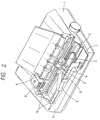
- Fig. 2 is a schematic illustration in perspective of an example of the structure of a liquid ejection recording apparatus having a liquid ejection recording head which uses thermal energy as the liquid ejection energy.
- a liquid ejection recording head (recording head) 2 is mounted on a carriage 3 which is scanned right and left along a slide shaft 10 by a carriage drive motor (CR motor, not shown) and a carriage drive belt 11.
- An electrical signal from a main board 7 is supplied to the recording head 2 via a flexible printed circuit (FPC) wiring 6.
- Recording liquid in an ink cartridge (not shown) within the liquid ejection recording apparatus 1 is supplied to the liquid ejection recording head 2 via a tube 5 and a sub-ink tank 4 on the carriage 3.
- An absorption recovery apparatus (absorption recovery mechanism) is mounted on the liquid ejection recording head 2 at the home position of the carriage 3 of the liquid ejection recording apparatus 1, because defective ejection occurs in rare occasions due to entered bubbles, attachment of recording liquid to the surface of an orifice, and the like.
- a recording medium is fed onto a platen 9 by a paper feed motor (LF motor, not shown). Information is recorded on the recording medium by moving the recording medium and scanning the recording head 2 right and left.
- Fig. 3 is a block diagram showing an example of the structure of a control unit (main board 7) of the liquid ejection recording apparatus 1.
- control unit print data from a host computer for example is received, print data of one line is stored, and the recording head is controlled by a head controller to print the data.
- a PPI (Programmable Peripheral Interface) 601 receives print data sent in parallel from a host computer of the recording apparatus of this embodiment, and sends the print data to a CPU 602.
- CPU 602 executes various procedures for the recording apparatus in accordance with the contents of a control ROM 603.
- a RAM 604 is used as a line buffer memory for storing print data of several lines received by PPI 601.
- a font generator ROM 605 stores fonts of print data.
- Control ROM 603 stores procedures to be executed by CPU 602. These memories are connected to an address bus and a data bus.
- An I/0 controller 606 is made of an IC dedicated to the control of a paper feed motor (LF motor) 607, a carriage drive motor (CR motor) 608, and an absorption recovery apparatus drive motor (pump motor) 609, to the data input/output control of a panel switch 610, to the control of a heat retaining heater 612 within the recording head 611, to the input control of temperature information from a temperature detecting means (thermistor) 613 within the recording head, and to other operations.
- LF motor paper feed motor
- CR motor carriage drive motor
- pump motor absorption recovery apparatus drive motor
- a head controller 614 is made of an IC dedicated to latch print data and print output time data, and sends print output to the recording head 611 in response to an instruction from CPU 602.
- the recording head 611 ejects recording liquid in accordance with the print data and print output time data from the head controller 614, to thereby record the print data on the recording material.
- Fig. 4 is a side view schematically showing an example of the structure of a liquid ejection recording head, particularly a recording head unit using heat as ejection energy.
- a base plate 13 On a base plate 13, there are mounted a printed circuit board (PCB) 14, a thermistor 19 for detecting the temperature of the recording head, and an ejection element 18 constituted by an orifice for ejecting recording liquid, an electricity-heat conversion member, and a liquid chamber.
- Print data from FPC 6 is supplied to the ejection element 18 when a head connector 12 on FPC 6 is coupled to a connector 15 of the printed circuit board 14 electrically connected to the recording head.
- Recording liquid is supplied to the ejection element 18 via an ink supply tube 17 and a liquid reservoir 20 integrally mounted within a holder 16 which protects the main part of the recording head.
- Fig. 5 is a schematic illustration of the main part of the recording head 2.
- the ejection element 18 is constructed of an electricity-heat conversion element 23 mounted on a Si substrate 21 for serving as an ejection energy generator, head heat retaining heaters 25 and 26 for heating the recording head and serving as another electricity-heat conversion member different from the ejection energy generator, an A1 wiring 27 for transmitting power to the electricity-heat conversion element 23 and the heat retaining heater 25, a member 24 joined to the Si substrate 21, and a filter 29 joined to the member 24.
- the member 24 is formed with recesses constituting, when it is joined to the Si substrate 21, orifices 22, liquid paths communicating with orifices 22, and a liquid chamber 28 communicating with the liquid paths.
- the filter 29 is used for removing impurities such as dusts contained in the liquid introduced into the liquid chamber 28.
- the member 24 is not limited as shown in Fig. 5, but it may take various configurations. Further, it is not limited to be formed integral as a whole, but it may be formed by discrete elements. For example, the wall portions of the liquid paths may be formed with a hardened film of photosensitive resin, and another plate member may be attached on the wall portions. The structure of the recording head may thus be changed as desired.
- the thermal energy generated by the electricity-heat conversion member (electricity-heat conversion element 23) is mostly (e.g. 50% or more) consumed in raising the temperature of liquid and ejecting several liquid droplets.
- the actual energy consumed for raising the temperature of the recording head is therefore several tens % of the remaining energy, because the heated liquid droplets are ejected out of the recording head and the heat transmitted to the substrate is dissipated out of it.
- Fig. 7 shows an example of temperature rise when a print signal is supplied, with and without recording liquid (ink) being supplied to the recording head.
- the present embodiment concerns a liquid ejection recording apparatus which ejects out liquid using the above-described thermal energy.
- the present embodiment uses a difference of temperature rise of a recording head between a normal printing operation and a non-ejection operation, as shown in Fig. 8. Assuming that the preset temperature rise rate is, for example, 10°C/10 seconds, the temperature rises at a smaller rate than this preset rate during the normal print, and at a larger rate during non-ejection. This difference is detected to perform various processes.
- Fig. 1 is a flow chart illustrating the control procedure of the preferred embodiment of this invention.
- step 102 After turning on the apparatus power (step 101), it is checked if there is any printing signal (step 102). If a printing signal has been entered, the temperature of the recording head is detected and set as Temp 1 (step 103). Next, after resetting a timer, the contents thereof are counted and set as Time 1 (step 104). One dot is printed in accordance with the printing signal (step 105), and thereafter it is checked if the printed dot is the last dot of the printing signal (step 106). If printing is not still completed, it is checked if the count time Time 1 is larger than 10 seconds (step 107). If the count time Time 1 is smaller than 10 seconds, the control returns to step 105 and repeats the above steps.
- the temperature of the recording head is detected and set as Temp 2 (step 108). It is checked if the value of Temp 2 subtracted by Temp 1 is equal to or higher than 10°C (step 109). If this value is smaller than 10°C, Temp 2 is set as Temp 1 (step 113) to return to step (104 and repeat the above steps. If the temperature difference is equal to or higher than 10°C (step 109), it is first checked if the temperature Temp 2 of the recording head is in excess of 70°C (step 401). If not, printing is stopped, and the recording head is returned to the home position and capped (step 301). Succeedingly, a recovery operation is performed using an absorption recovery mechanism 8 (step 302) and the apparatus is made off-line (step 303).
- step 401 if the temperature is in excess of 70°C (step 401), then the recording head driving voltage Vh is turned off (step 402).
- a relay 616 is connected to the I/0 controller, and the contacts 617 of the relay 616 are connected as shown in Fig. 6C.
- the relay 616 is driven to open the contacts 617 and hence turn off the recording head driving voltage Vh).
- the power supply to the recording apparatus may be cut off (step 402).
- the recording head driving voltage Vh is turned off or the power supply to the recording apparatus is stopped, to thereby stop heating by the heat retaining heaters.
- the temperature 70°C maybe set as desired in accordance with the characteristics and performance of the recording head and the apparatus. This temperature should be set to such a value higher than a temperature under which normal printing is possible with all orifices of the recording head continuously ejecting recording liquid.
- time is checked every time one dot has been printed.
- the temperature of the recording head may be checked every one second, every one character, or every one predetermined print area, and if the temperature rise becomes equal to or higher than 10°C per 10 seconds or per predetermined print time, then provided the temperature is not excessive, it is considered as non-ejection.
- the 10°C/10 seconds has been used as a reference value, obviously it may be set as desired in accordance with the characteristic of the recording head, and the characteristic and structure of the apparatus.
- control may be returned directly to step 103 to detect again Temp 1.
- an abnormal state of the recording head can be detected at an early stage, thereby providing an apparatus with improved safety and without irreversible damage, such as breakage of the recording head or the apparatus occurring.
- the recording apparatus automatically stops its printing operation and performs a recovery operation, thereby minimizing deterioration of printing quality.
- the recording apparatus automatically stops its heating, thereby providing a recording apparatus and control method with high safety.
- the present invention is particularly advantageous if it is applied to a bubble jet type recording head and apparatus of an ink jet recording type.
- the typical structure and principle of the bubble jet type are preferably those disclosed, e.g. in the specifications of USP 4,723,129 and USP 4,740,796.
- This principle is applicable to both a so-called on-demand type and a continuous type.
- the on-demand type is particularly useful.
- at least one drive signal corresponding to record information is applied to an electricity-heat conversion member disposed at a liquid (ink) containing sheet or liquid path so that a rapid temperature rise in excess of nucleate boiling is provided.
- Thermal energy generated by the electricity-heat conversion member causes film boiling at the thermal acting surface of the recording head so that a bubble in one-to-one correspondence with the drive signal will be formed within the liquid (ink).
- a liquid (ink) is ejected out of an orifice to form one droplet. It is more preferable that if a pulse signal is used for this drive signal, since a bubble can be grown and contracted rapidly and properly, and a liquid (ink) can be ejected out with good response characteristics.
- this pulse-like drive signal it is preferable to use such a signal as disclosed in the specifications of USP 4,463,359, and USP 4,345,262. Excellent printing can be made if there are adopted the conditions described in the specification of USP 4,313,124 regarding the temperature rise rate at the heat acting surface.
- Structures of recording heads that can be used in the embodiment of this invention can include not only a combination of structures of orifices, liquid paths, electricity-heat conversion members disclosed in the above-mentioned specifications, but also structures having a heat acting surface disposed in a bending area as disclosed in the specifications of USP 4,558,333, and USP 4,459,600. Further, this invention may advantageously adopt the structure disclosed in Japanese Laid-open Application No. 59-123670 wherein a slit shared by a plurality of electricity-heat conversion members is used as an orifice, or the structure disclosed in Japanese Laid-open Application No. 59-138461 wherein an opening for absorbing a pressure wave of heat energy is formed facing an orifice.
- a full line type recording head having a length same as the width of a maximum recording medium the apparatus allowed to print, may also be used, with the above-described advantageous effects being further enhanced.
- a recording head may be constructed of a plurality of recording heads disclosed in the above-mentioned specifications, or may be constructed of a single integral recording head.
- This invention is also applicable to a chip type recording head which is detachably mounted on the apparatus for electrical connection and ink supply, and to a cartridge type recording head having a built-in ink supply.
- Additional mounting of recovery means for a recording head, auxiliary means, and the like as described previously is preferable since the advantageous effects of this invention can be reliably ensured.
- additional means include capping means, cleaning means, pressurising or absorbing means, respectively for a recording head, and auxiliary heating means for an electricity-heat conversion member, a different heating element, or a combination thereof. It is also effective for stable printing to provide an auxiliary ejection mode different from an ejection for printing.
- the present invention is particularly useful not only for an apparatus having a recording mode with only a main colour such as black, but also for an apparatus having a recording mode with different multiple colours or compound full colours using either an integral recording head or a plurality of recording heads.
Landscapes
- Ink Jet (AREA)
- Particle Formation And Scattering Control In Inkjet Printers (AREA)
- Catching Or Destruction (AREA)
- Electrical Discharge Machining, Electrochemical Machining, And Combined Machining (AREA)
Claims (8)
- Appareil d'enregistrement à jet d'encre comprenant :
un moyen d'enregistrement (2) pour enregistrer l'information, et comportant une pluralité d'orifices (22) d'éjection d'encre et une pluralité d'éléments (23) de génération d'énergie, chacun des éléments (23) générant de l'énergie pour éjecter des gouttelettes d'encre en fonction de données d'image et est associé avec un orifice correspondant desdits orifices (22) d'encre;
un moyen de détection (19; 613) pour détecter une température (Temp 1, Temp 2) dudit moyen d'enregistrement (2) au début et à la fin d'intervalles de temps prédéterminés respectifs au cours d'une opération d'enregistrement pour délivrer des valeurs de détection; et
un moyen de commande (601-616), qui coopère avec ledit moyen de détection (19; 613), et qui peut fonctionner pour déterminer si oui ou non la différence (Temp 2 - Temp 1) des températures (Temp 1, Temp 2) détectées au début et à la fin de tout intervalle de temps prédéterminé respectif excède une valeur de référence; ledit appareil d'enregistrement à jet d'encre étant caractérisé en ce que:
ledit moyen de commande (601-616) peut aussi fonctionner pour déterminer si oui ou non la température (Temp 2) détectée à la fin de l'intervalle de temps prédéterminé respectif excède une température prédéterminée;
et, dans l'éventualité où il est déterminé qu'à la fois ladite valeur de référence et ladite température prédéterminée sont dépassées, ledit moyen de commande (601-616) peut fonctionner, soit pour interrompre une tension de commande (VH) appliquée audit moyen d'enregistrement, soit pour interrompre la puissance appliquée audit appareil d'enregistrement à jet d'encre. - Appareil selon la revendication 1, dans lequel ledit moyen de commande (601-616) comporte un moyen d'interruption de la puissance appliquée à l'appareil.
- Appareil selon la revendication 1 ou 2, comportant un moyen de rétablissement (609) pour rétablir la condition d'éjection d'encre par éjection d'encre depuis les orifices d'encre dudit moyen d'enregistrement, et dans lequel ledit moyen de commande (601-616) peut fonctionner pour conduire ledit moyen de rétablissement (609) à réaliser son opération de rétablissement lorsqu'il est déterminé que ladite valeur de référence est dépassée et que la température prédéterminée n'est pas dépassée.
- Appareil selon l'une quelconque des revendications précédentes, dans lequel ladite température prédéterminée est supérieure à une température dudit moyen d'enregistrement pour laquelle un enregistrement régulier ou ordinaire est possible tandis que tous les orifices (22) dudit support d'enregistrement (2) éjectent l'encre en continu.
- Appareil selon l'une quelconque des revendications précédentes, comprenant en outre un moyen (3) formant chariot pour déplacer ledit moyen d'enregistrement (2) dans une direction de balayage principale différente de la direction d'agencement des orifices (22).
- Appareil selon l'une quelconque des revendications précédentes, dans lequel ledit moyen d'enregistrement (2) comporte un dispositif de chauffage (25, 26) retenant la chaleur.
- Appareil selon l'une quelconque des revendications précédentes, dans lequel lesdits éléments (23) de génération d'énergie comprennent chacun un convertisseur électrothermique pour générer l'énergie afin d'éjecter une gouttelette d'encre.
- Procédé d'enregistrement utilisant un appareil d'enregistrement à jet d'encre comportant un moyen d'enregistrement (2) pour enregistrer l'information et un moyen de détection (19; 613) pour détecter la température (Temp 1, Temp 2) dudit moyen d'enregistrement au début et à la fin d'intervalles de temps prédéterminés respectifs, ce procédé comportant la comparaison de la différence (Temp 2 - Temp 1) des températures (Temp 1, Temp 2) détectées au début et à la fin de chaque intervalle de temps prédéterminé respectif avec une valeur de référence; dans lequel
ledit procédé est caractérisé par les étapes suivantes:
comparaison de la température (Temp 2) détectée à la fin de chaque intervalle de temps prédéterminé respectif avec une température prédéterminée; et
soit interruption d'une tension de commande (VH) appliquée audit moyen d'enregistrement (2), soit interruption de la puissance appliquée à l'appareil, dans l'éventualité où à la fois ladite valeur de référence et ladite température prédéterminée sont dépassées.
Applications Claiming Priority (2)
| Application Number | Priority Date | Filing Date | Title |
|---|---|---|---|
| JP31730/90 | 1990-02-13 | ||
| JP2031730A JP2756335B2 (ja) | 1990-02-13 | 1990-02-13 | 液体噴射記録装置 |
Publications (3)
| Publication Number | Publication Date |
|---|---|
| EP0442705A2 EP0442705A2 (fr) | 1991-08-21 |
| EP0442705A3 EP0442705A3 (en) | 1991-10-16 |
| EP0442705B1 true EP0442705B1 (fr) | 1995-08-09 |
Family
ID=12339161
Family Applications (1)
| Application Number | Title | Priority Date | Filing Date |
|---|---|---|---|
| EP91301129A Expired - Lifetime EP0442705B1 (fr) | 1990-02-13 | 1991-02-12 | Appareil d'enregistrement par expulsion de liquide et méthode de commande |
Country Status (6)
| Country | Link |
|---|---|
| US (1) | US5502469A (fr) |
| EP (1) | EP0442705B1 (fr) |
| JP (1) | JP2756335B2 (fr) |
| AT (1) | ATE126128T1 (fr) |
| DE (1) | DE69111844T2 (fr) |
| ES (1) | ES2075932T3 (fr) |
Families Citing this family (15)
| Publication number | Priority date | Publication date | Assignee | Title |
|---|---|---|---|---|
| CA2074906C (fr) * | 1991-08-01 | 2000-09-12 | Hiromitsu Hirabayashi | Appareil d'enregistrement a jet d'encre a fonction de controle de la temperature |
| CA2085551C (fr) * | 1991-12-19 | 1997-11-25 | Atsushi Arai | Appareil et methode d'enregistrement a jet d'encre |
| JP3297465B2 (ja) * | 1992-05-08 | 2002-07-02 | キヤノン株式会社 | インクジェット記録装置、インクジェット記録ヘッドの温度特性検知方法およびインクジェット記録ヘッドの吐出状態判断方法 |
| EP0924084B1 (fr) * | 1993-05-27 | 2006-03-08 | Canon Kabushiki Kaisha | Appareil d'enregistrement à jet d'encre contrôlé par température presumée et méthode de contrôle associée |
| JP3397371B2 (ja) * | 1993-05-27 | 2003-04-14 | キヤノン株式会社 | 記録装置および記録方法 |
| JP3402766B2 (ja) | 1994-07-29 | 2003-05-06 | キヤノン株式会社 | 記録装置、該記録装置の制御方法および記録方法 |
| JP3402767B2 (ja) * | 1994-07-29 | 2003-05-06 | キヤノン株式会社 | 記録装置および記録装置の制御方法 |
| JPH10309814A (ja) * | 1997-05-13 | 1998-11-24 | Fuji Xerox Co Ltd | 記録装置 |
| JP3674248B2 (ja) * | 1997-07-01 | 2005-07-20 | ブラザー工業株式会社 | インク噴射装置の駆動装置 |
| US6260940B1 (en) * | 1998-05-04 | 2001-07-17 | Canon Kabushiki Kaisha | Ink jet printing system having ink preheating during non-printing periods |
| US6116712A (en) * | 1998-10-13 | 2000-09-12 | Xerox Corporation | Method and apparatus for compensating for thermal conditioning in an ink jet print head |
| AUPP702498A0 (en) * | 1998-11-09 | 1998-12-03 | Silverbrook Research Pty Ltd | Image creation method and apparatus (ART77) |
| US20070273731A1 (en) * | 2006-05-26 | 2007-11-29 | Icf Technology Limited | Method for driving an ink jet head having piezoelectric actuator |
| JP4827625B2 (ja) * | 2006-06-14 | 2011-11-30 | キヤノン株式会社 | 記録ヘッドの吐出検査方法、記録装置 |
| JP4997904B2 (ja) * | 2006-10-06 | 2012-08-15 | 富士ゼロックス株式会社 | 画像記録ヘッド及び画像形成装置 |
Citations (1)
| Publication number | Priority date | Publication date | Assignee | Title |
|---|---|---|---|---|
| EP0353925A2 (fr) * | 1988-07-26 | 1990-02-07 | Canon Kabushiki Kaisha | Couche de base pour enregistrement à jet d'encre, tête d'enregistrement et appareil l'utilisant |
Family Cites Families (27)
| Publication number | Priority date | Publication date | Assignee | Title |
|---|---|---|---|---|
| DE2659398A1 (de) * | 1976-12-29 | 1978-07-06 | Siemens Ag | Heizvorrichtung fuer schreibkoepfe in tintenmosaikschreibeinrichtungen |
| CA1127227A (fr) * | 1977-10-03 | 1982-07-06 | Ichiro Endo | Procede d'enregistrement a jet liquide et appareil d'enregistrement |
| US4330787A (en) * | 1978-10-31 | 1982-05-18 | Canon Kabushiki Kaisha | Liquid jet recording device |
| US4345262A (en) * | 1979-02-19 | 1982-08-17 | Canon Kabushiki Kaisha | Ink jet recording method |
| US4463359A (en) * | 1979-04-02 | 1984-07-31 | Canon Kabushiki Kaisha | Droplet generating method and apparatus thereof |
| US4313124A (en) * | 1979-05-18 | 1982-01-26 | Canon Kabushiki Kaisha | Liquid jet recording process and liquid jet recording head |
| JPS56146764A (en) * | 1980-04-16 | 1981-11-14 | Ricoh Co Ltd | Head protecting system in ink jet printer |
| JPS56146763A (en) * | 1980-04-16 | 1981-11-14 | Ricoh Co Ltd | Mechanism for removing blocking of head for ink jet printer |
| US4558333A (en) * | 1981-07-09 | 1985-12-10 | Canon Kabushiki Kaisha | Liquid jet recording head |
| GB2112715B (en) * | 1981-09-30 | 1985-07-31 | Shinshu Seiki Kk | Ink jet recording apparatus |
| JPS58118267A (ja) * | 1982-01-08 | 1983-07-14 | Canon Inc | 液体吐出装置 |
| JPS58155960A (ja) * | 1982-03-10 | 1983-09-16 | Konishiroku Photo Ind Co Ltd | インクジエツト記録装置 |
| JPS58194564A (ja) * | 1982-05-11 | 1983-11-12 | Canon Inc | インクジェット装置 |
| JPS58220757A (ja) * | 1982-06-18 | 1983-12-22 | Canon Inc | 液体噴射記録装置 |
| JPS59123670A (ja) * | 1982-12-28 | 1984-07-17 | Canon Inc | インクジエツトヘツド |
| JPS59138461A (ja) * | 1983-01-28 | 1984-08-08 | Canon Inc | 液体噴射記録装置 |
| US4626875A (en) * | 1983-09-26 | 1986-12-02 | Canon Kabushiki Kaisha | Apparatus for liquid-jet recording wherein a potential is applied to the liquid |
| JPS60118170U (ja) * | 1984-01-19 | 1985-08-09 | 富士ゼロックス株式会社 | 定着装置の異常温度防止装置 |
| US4660056A (en) * | 1984-03-23 | 1987-04-21 | Canon Kabushiki Kaisha | Liquid jet recording head |
| GB2169856B (en) * | 1984-12-28 | 1989-10-25 | Canon Kk | Liquid-discharge recording apparatus and a method of operation thereof |
| JPS61199975A (ja) * | 1985-03-04 | 1986-09-04 | Toshiba Corp | 画像形成装置 |
| JPH074940B2 (ja) * | 1985-03-12 | 1995-01-25 | キヤノン株式会社 | インクジエツト記録装置 |
| JPS61272811A (ja) * | 1985-05-28 | 1986-12-03 | Ricoh Co Ltd | 温度制御装置 |
| JPS6287354A (ja) * | 1985-10-15 | 1987-04-21 | Sanyo Electric Co Ltd | インクジエツトプリンタの温度制御装置 |
| US4636812A (en) * | 1985-10-24 | 1987-01-13 | Dynamics Research Corporation | Thermal print head temperature control |
| JP2661063B2 (ja) * | 1987-09-24 | 1997-10-08 | アイシン精機株式会社 | サーマルヘッド保護装置 |
| JP2724158B2 (ja) * | 1988-06-17 | 1998-03-09 | キヤノン株式会社 | インクジェット記録装置 |
-
1990
- 1990-02-13 JP JP2031730A patent/JP2756335B2/ja not_active Expired - Fee Related
-
1991
- 1991-02-12 EP EP91301129A patent/EP0442705B1/fr not_active Expired - Lifetime
- 1991-02-12 DE DE69111844T patent/DE69111844T2/de not_active Expired - Lifetime
- 1991-02-12 AT AT91301129T patent/ATE126128T1/de not_active IP Right Cessation
- 1991-02-12 ES ES91301129T patent/ES2075932T3/es not_active Expired - Lifetime
-
1994
- 1994-08-22 US US08/293,417 patent/US5502469A/en not_active Expired - Lifetime
Patent Citations (1)
| Publication number | Priority date | Publication date | Assignee | Title |
|---|---|---|---|---|
| EP0353925A2 (fr) * | 1988-07-26 | 1990-02-07 | Canon Kabushiki Kaisha | Couche de base pour enregistrement à jet d'encre, tête d'enregistrement et appareil l'utilisant |
Also Published As
| Publication number | Publication date |
|---|---|
| US5502469A (en) | 1996-03-26 |
| ATE126128T1 (de) | 1995-08-15 |
| JPH03234657A (ja) | 1991-10-18 |
| EP0442705A3 (en) | 1991-10-16 |
| ES2075932T3 (es) | 1995-10-16 |
| JP2756335B2 (ja) | 1998-05-25 |
| EP0442705A2 (fr) | 1991-08-21 |
| DE69111844D1 (de) | 1995-09-14 |
| DE69111844T2 (de) | 1996-01-11 |
Similar Documents
| Publication | Publication Date | Title |
|---|---|---|
| EP0442705B1 (fr) | Appareil d'enregistrement par expulsion de liquide et méthode de commande | |
| US5576745A (en) | Recording apparatus having thermal head and recording method | |
| JP3487584B2 (ja) | インクジェット記録装置、および該装置における記録ヘッドの吐出状態を回復させる方法 | |
| US5880751A (en) | Ink jet recording apparatus and ink droplet amount ejection control method therefor | |
| US6382764B1 (en) | Printing method and apparatus for counting number of ejected ink droplets for controlling printhead recovery | |
| JP3060347B2 (ja) | 記録装置 | |
| EP0593041B1 (fr) | Appareil d'enregistrement à jet d'encre | |
| EP0732217B1 (fr) | Tête et appareil d'enregistrement pour la détection de contact | |
| JPH11192724A (ja) | インクジェットプリント装置およびインク有無判定方法 | |
| US6761424B2 (en) | Image print apparatus and control method thereof | |
| JP3162892B2 (ja) | 液体噴射記録装置及び該装置におけるヘッド温度制御方法 | |
| JP3466732B2 (ja) | インクジェット記録装置 | |
| JPH05220965A (ja) | インクジェット記録装置 | |
| JP3124022B2 (ja) | インクジェット記録装置および不吐出検知方法 | |
| JPH10109409A (ja) | インクジェット記録装置及びその制御方法 | |
| JPH03234621A (ja) | 記録装置 | |
| JPH06238906A (ja) | インクジェット記録装置 | |
| JP3253105B2 (ja) | インクジェット記録装置およびインクジェット記録方法 | |
| JP3181813B2 (ja) | ファクシミリ装置及びその記録制御方法 | |
| JP2960604B2 (ja) | 不吐出検知方法およびこれによるインクジェット記録装置 | |
| JPH03136865A (ja) | インクジェット記録装置 | |
| JP2001096732A (ja) | インクジェット記録装置 | |
| JPH03218845A (ja) | インクジェットプリンタ | |
| JP2001150697A (ja) | 走査装置 | |
| JPH04286654A (ja) | 記録装置 |
Legal Events
| Date | Code | Title | Description |
|---|---|---|---|
| PUAI | Public reference made under article 153(3) epc to a published international application that has entered the european phase |
Free format text: ORIGINAL CODE: 0009012 |
|
| AK | Designated contracting states |
Kind code of ref document: A2 Designated state(s): AT BE CH DE DK ES FR GB GR IT LI LU NL SE |
|
| PUAL | Search report despatched |
Free format text: ORIGINAL CODE: 0009013 |
|
| AK | Designated contracting states |
Kind code of ref document: A3 Designated state(s): AT BE CH DE DK ES FR GB GR IT LI LU NL SE |
|
| 17P | Request for examination filed |
Effective date: 19920309 |
|
| 17Q | First examination report despatched |
Effective date: 19931020 |
|
| GRAA | (expected) grant |
Free format text: ORIGINAL CODE: 0009210 |
|
| AK | Designated contracting states |
Kind code of ref document: B1 Designated state(s): AT BE CH DE DK ES FR GB GR IT LI LU NL SE |
|
| PG25 | Lapsed in a contracting state [announced via postgrant information from national office to epo] |
Ref country code: NL Free format text: LAPSE BECAUSE OF FAILURE TO SUBMIT A TRANSLATION OF THE DESCRIPTION OR TO PAY THE FEE WITHIN THE PRESCRIBED TIME-LIMIT Effective date: 19950809 Ref country code: CH Effective date: 19950809 Ref country code: BE Effective date: 19950809 Ref country code: AT Effective date: 19950809 Ref country code: DK Effective date: 19950809 Ref country code: LI Effective date: 19950809 Ref country code: GR Free format text: LAPSE BECAUSE OF FAILURE TO SUBMIT A TRANSLATION OF THE DESCRIPTION OR TO PAY THE FEE WITHIN THE PRESCRIBED TIME-LIMIT Effective date: 19950809 |
|
| REF | Corresponds to: |
Ref document number: 126128 Country of ref document: AT Date of ref document: 19950815 Kind code of ref document: T |
|
| REF | Corresponds to: |
Ref document number: 69111844 Country of ref document: DE Date of ref document: 19950914 |
|
| ET | Fr: translation filed | ||
| REG | Reference to a national code |
Ref country code: ES Ref legal event code: FG2A Ref document number: 2075932 Country of ref document: ES Kind code of ref document: T3 |
|
| ITF | It: translation for a ep patent filed | ||
| PG25 | Lapsed in a contracting state [announced via postgrant information from national office to epo] |
Ref country code: SE Effective date: 19951109 |
|
| NLV1 | Nl: lapsed or annulled due to failure to fulfill the requirements of art. 29p and 29m of the patents act | ||
| PG25 | Lapsed in a contracting state [announced via postgrant information from national office to epo] |
Ref country code: LU Free format text: LAPSE BECAUSE OF NON-PAYMENT OF DUE FEES Effective date: 19960229 |
|
| PLBE | No opposition filed within time limit |
Free format text: ORIGINAL CODE: 0009261 |
|
| STAA | Information on the status of an ep patent application or granted ep patent |
Free format text: STATUS: NO OPPOSITION FILED WITHIN TIME LIMIT |
|
| 26N | No opposition filed | ||
| REG | Reference to a national code |
Ref country code: GB Ref legal event code: IF02 |
|
| PGFP | Annual fee paid to national office [announced via postgrant information from national office to epo] |
Ref country code: ES Payment date: 20090108 Year of fee payment: 19 |
|
| PGFP | Annual fee paid to national office [announced via postgrant information from national office to epo] |
Ref country code: IT Payment date: 20090205 Year of fee payment: 19 |
|
| PGFP | Annual fee paid to national office [announced via postgrant information from national office to epo] |
Ref country code: FR Payment date: 20090223 Year of fee payment: 19 |
|
| PGFP | Annual fee paid to national office [announced via postgrant information from national office to epo] |
Ref country code: GB Payment date: 20100219 Year of fee payment: 20 Ref country code: DE Payment date: 20100228 Year of fee payment: 20 |
|
| REG | Reference to a national code |
Ref country code: FR Ref legal event code: ST Effective date: 20101029 |
|
| PG25 | Lapsed in a contracting state [announced via postgrant information from national office to epo] |
Ref country code: FR Free format text: LAPSE BECAUSE OF NON-PAYMENT OF DUE FEES Effective date: 20100301 |
|
| REG | Reference to a national code |
Ref country code: DE Ref legal event code: R071 Ref document number: 69111844 Country of ref document: DE |
|
| REG | Reference to a national code |
Ref country code: GB Ref legal event code: PE20 Expiry date: 20110211 |
|
| REG | Reference to a national code |
Ref country code: ES Ref legal event code: FD2A Effective date: 20110228 |
|
| PG25 | Lapsed in a contracting state [announced via postgrant information from national office to epo] |
Ref country code: IT Free format text: LAPSE BECAUSE OF NON-PAYMENT OF DUE FEES Effective date: 20100212 |
|
| PG25 | Lapsed in a contracting state [announced via postgrant information from national office to epo] |
Ref country code: ES Free format text: LAPSE BECAUSE OF NON-PAYMENT OF DUE FEES Effective date: 20110213 Ref country code: GB Free format text: LAPSE BECAUSE OF EXPIRATION OF PROTECTION Effective date: 20110211 |
|
| PG25 | Lapsed in a contracting state [announced via postgrant information from national office to epo] |
Ref country code: DE Free format text: LAPSE BECAUSE OF EXPIRATION OF PROTECTION Effective date: 20110212 |