EP0442706B1 - Leitfähiges Blatt für Aufzeichnungskopf eines Aufzeichnungsgerätes - Google Patents
Leitfähiges Blatt für Aufzeichnungskopf eines Aufzeichnungsgerätes Download PDFInfo
- Publication number
- EP0442706B1 EP0442706B1 EP91301130A EP91301130A EP0442706B1 EP 0442706 B1 EP0442706 B1 EP 0442706B1 EP 91301130 A EP91301130 A EP 91301130A EP 91301130 A EP91301130 A EP 91301130A EP 0442706 B1 EP0442706 B1 EP 0442706B1
- Authority
- EP
- European Patent Office
- Prior art keywords
- electrically conductive
- recording head
- conductive members
- recording
- substrate
- Prior art date
- Legal status (The legal status is an assumption and is not a legal conclusion. Google has not performed a legal analysis and makes no representation as to the accuracy of the status listed.)
- Expired - Lifetime
Links
Images




Classifications
-
- B—PERFORMING OPERATIONS; TRANSPORTING
- B41—PRINTING; LINING MACHINES; TYPEWRITERS; STAMPS
- B41J—TYPEWRITERS; SELECTIVE PRINTING MECHANISMS, i.e. MECHANISMS PRINTING OTHERWISE THAN FROM A FORME; CORRECTION OF TYPOGRAPHICAL ERRORS
- B41J2/00—Typewriters or selective printing mechanisms characterised by the printing or marking process for which they are designed
- B41J2/005—Typewriters or selective printing mechanisms characterised by the printing or marking process for which they are designed characterised by bringing liquid or particles selectively into contact with a printing material
- B41J2/01—Ink jet
- B41J2/135—Nozzles
- B41J2/14—Structure thereof only for on-demand ink jet heads
- B41J2/14016—Structure of bubble jet print heads
- B41J2/14072—Electrical connections, e.g. details on electrodes, connecting the chip to the outside...
-
- B—PERFORMING OPERATIONS; TRANSPORTING
- B41—PRINTING; LINING MACHINES; TYPEWRITERS; STAMPS
- B41J—TYPEWRITERS; SELECTIVE PRINTING MECHANISMS, i.e. MECHANISMS PRINTING OTHERWISE THAN FROM A FORME; CORRECTION OF TYPOGRAPHICAL ERRORS
- B41J2/00—Typewriters or selective printing mechanisms characterised by the printing or marking process for which they are designed
- B41J2/005—Typewriters or selective printing mechanisms characterised by the printing or marking process for which they are designed characterised by bringing liquid or particles selectively into contact with a printing material
- B41J2/01—Ink jet
- B41J2/135—Nozzles
- B41J2/14—Structure thereof only for on-demand ink jet heads
- B41J2/14016—Structure of bubble jet print heads
- B41J2/14024—Assembling head parts
-
- B—PERFORMING OPERATIONS; TRANSPORTING
- B41—PRINTING; LINING MACHINES; TYPEWRITERS; STAMPS
- B41J—TYPEWRITERS; SELECTIVE PRINTING MECHANISMS, i.e. MECHANISMS PRINTING OTHERWISE THAN FROM A FORME; CORRECTION OF TYPOGRAPHICAL ERRORS
- B41J2/00—Typewriters or selective printing mechanisms characterised by the printing or marking process for which they are designed
- B41J2/005—Typewriters or selective printing mechanisms characterised by the printing or marking process for which they are designed characterised by bringing liquid or particles selectively into contact with a printing material
- B41J2/01—Ink jet
- B41J2/135—Nozzles
- B41J2/14—Structure thereof only for on-demand ink jet heads
- B41J2002/14379—Edge shooter
-
- H—ELECTRICITY
- H05—ELECTRIC TECHNIQUES NOT OTHERWISE PROVIDED FOR
- H05K—PRINTED CIRCUITS; CASINGS OR CONSTRUCTIONAL DETAILS OF ELECTRIC APPARATUS; MANUFACTURE OF ASSEMBLAGES OF ELECTRICAL COMPONENTS
- H05K3/00—Apparatus or processes for manufacturing printed circuits
- H05K3/30—Assembling printed circuits with electric components, e.g. with resistors
- H05K3/32—Assembling printed circuits with electric components, e.g. with resistors electrically connecting electric components or wires to printed circuits
- H05K3/325—Assembling printed circuits with electric components, e.g. with resistors electrically connecting electric components or wires to printed circuits by abutting or pinching; Mechanical auxiliary parts therefor
-
- H—ELECTRICITY
- H05—ELECTRIC TECHNIQUES NOT OTHERWISE PROVIDED FOR
- H05K—PRINTED CIRCUITS; CASINGS OR CONSTRUCTIONAL DETAILS OF ELECTRIC APPARATUS; MANUFACTURE OF ASSEMBLAGES OF ELECTRICAL COMPONENTS
- H05K3/00—Apparatus or processes for manufacturing printed circuits
- H05K3/36—Assembling printed circuits with other printed circuits
- H05K3/368—Assembling printed circuits with other printed circuits parallel to each other
Definitions
- This invention relates to an electrically conductive sheet, a recording head incorporating an electrically conductive sheet and an ink jet recording apparatus incorporating such a recording head.
- An ink jet recording head as used in an ink jet recording apparatus has an element substrate which is a first substrate on which recording elements (energy generating bodies) for discharging ink are mounted and a driving substrate which is a second substrate for supplying driving signals for driving the recording elements on the element substrate, these substrates being electrically connected to each other.
- the electrically conductive sheet 61 is provided with a plurality of the same columnar electrically conductive members 63 buried therein substantially vertically.
- the members 63 are arranged in three rows at a predetermined pitch interval L11 as is shown in Fig. 6. These members 63 are exposed at one end thereof on one surface of the electrically conductive sheet 51 and at the other end thereof on the other surface of the electrically conductive sheet 51.
- Fig. 7 shows an ink jet recording head in which the electrically conductive sheet 61 is sandwiched between the element substrate 72 and the driving substrate 73 and provides electric connection therebetween
- Fig. 8 is a partially expanded view showing in detail the connection portion.
- the element substrate 72 mounting at one end thereof an ink accommodating chamber member 74 is connected at its other end to one end of the driving substrate through the electrically conductive sheet.
- a plurality of wiring pads are provided on the respective substrates 72 and 73, respectively, which correspond to each other and are opposed to each other.
- the corresponding wiring pads on the respective substrates are electrically connected to each other by pressing them to the corresponding columnar electrically conductive member 63 or by providing alloy junctions between the wiring pads 86 and 87 and the corresponding columnar electrically conductive members 63.
- the pitch interval defining the distribution density of the arrangement of the wiring pads provided on the element substrate 72 and the driving substrate 73, respectively, is typically made different according to the amount of currents flowing through each pad in the light of electrical insulation.
- the wiring pads 86 and 87 on the element substrate 72 and the driving substrate 73, respectively are arranged at two different intervals l11 and l12 (l11 ⁇ l12). So, the pitch interval L11 defining the distribution density of the electrically conductive members 63 buried in the insulator 62 is made smaller than the pitch interval l12 and is made equal to the smaller interval l11.
- the numbers of the electrically conductive members 63 connected to the respective wiring pads are the same in spite of the amount of current therethrough and the respective electrically conductive members 63 are the same in shape, the current flows through the respective conductive members at different amounts, and the amount of heat generation thereby is different between the electrically conductive members 63. Therefore, there is caused inequality (dispersion) in the amount of heat generated in parts, and this can, decrease the printing quality specially in a recording head using heating.
- an electrically conductive member through which the largest current flows deteriorates earliest. So, since the usable period of time for the recording head utilizing the above-mentioned sheet is determined by the life of the electrically conductive member carrying the largest current, it would be difficult to provide a long life recording head.
- This invention is intended as a solution to the above-mentioned problems of the prior art.
- a recording head incorporating an electrically conductive sheet, an electrically conductive sheet for use in a recording head, and a recording apparatus incorporating such recording head, each in accordance with the present invention, are set out in claims 1, 8 and 7, respectively, of the claims attached.
- the electrically conductive members aforesaid are not limited to being of circular cross-section, and may be of square or other shape cross-section.
- the term "diameter" denoting size is therefore to be construed as including equivalent measure of size.
- the distribution density thereof is caused to differ from one area to another.
- the diameter of the electrically conductive members uniform it is caused to differ from one area to another. Accordingly, the various disadvantages encountered in the prior art are brought into solution. For example, if the distribution density of the electrically conductive members is determined in dependance upon the distribution density of the plural wiring pads provided on the respective first and second substrates, it is possible to decrease the number of redundant electrically conductive metal members.
- the distribution density is determined in dependance upon the amount of current flowing between the related wiring pads of the respective substrates through the electrically conductive members, it is possible to make equal the current flowing through the respective metal members in amount, so that since the heating of and current concentration to specified electrically conductive members are prevented, the lives of the respective electrically conductive members are balanced, and thus, the life of the recording head can be prolonged and premature deterioration of recording quality can be avoided. It is also possible to obtain a similar effect when the electrically conductive members are varied in diameter in dependance upon the distribution density of the wiring pads and/or the amount of the current therethrough.
- the electrically conductive members can be varied in distribution density. Accordingly, it is possible to improve the yield of the production thereof and decrease the production cost thereof.
- the number of redundant electrically conductive members can be decreased by varying the diameter and/or distribution density of the electrically conductive members in dependance upon the distribution density of the respective wiring pads of the substrates. This contributes to high efficiency in addition to the above-mentioned advantage.
- the electrically conductive members can be balanced in lifetime and in rate of fatigue by varying the size and/or diameter in distribution density of the electrically conductive members depending on the amount of current flowing through the respective wiring pads of the substrates.
- the life of the electrically conductive sheet is prolonged, in addition to the above-mentioned advantages.
- Fig. 1 is a perspective view showing the external appearance of one embodiment of an electrically conductive sheet for use in a recording head according to this invention
- Fig. 2 is a partial section view showing an ink jet recording head, specially the situation of connecting an element substrate 24 and a driving substrate 25 by the electrically conductive sheet 11 intervened therebetween.
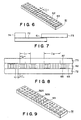
- the electrically conductive sheet 11 is a similar one to the prior art electrically conductive sheet 61 shown in Fig. 6 in that it has columnar electrically conductive members 13 buried therein and arranged in three rows, but in this invention, the pitch intervals at which the electrically conductive members 13 are disposed are made different, as shown, in dependence upon the distribution density of wiring pads (refer to Fig. 2) provided on the respective element substrate 24 and the driving substrate 25, which are electrically connected by the electrically conductive members 13.
- the electrically conductive members 13 are arranged at a pitch interval L1 in one area, i.e. at the left side in the drawing, and at a different pitch interval L2 which is wider than L1 in another area, i.e. at the right side.
- the wiring pads 26 and 27 provided on the respective element substrate 24 and the driving substrate 25 are arranged at the right and left of the respective substrates at pitch intervals l1 and l2 (l1 ⁇ l2), respectively, similarly to the case in the prior art. Since, as mentioned above, the pitch intervals L1 and L2 at which the electrically conductive members 13 buried in the electrically conducting sheet l1 are arranged depend upon the pitch intervals l1 and l2 at which the respective wiring pads 26 and 27 are arranged, respectively, the number of redundant electrically conductive members 13 (ones which do not contact the wiring pads at all) is minimised. Thus, it is possible to obtain low-cost recording heads using such arrangement.
- the pitch intervals L1 and L2 at which the electrically conductive members are arranged in the insulator 12 may be established in dependance upon the density of current flowing through the respective wiring pads 26 and 27, instead of setting up correspondingly to the pitch intervals l1 and l2 of the respective wiring pads 26 and 27 on the element substrate 24 and the driving substrate 25, respectively. Therefore, in this construction, more electrically conductive members 13 can contact the wiring pads of higher current density, so that it is possible to balance the amount of current through the respective electrically conductive members 13, and make uniform the heating amount from and life of the electrically conductive members 13.
- the sizes (i.e. diameters) of the respective wiring pads are all the same, it is also possible to obtain similar effects by causing the pitch at which the electrically conductive members are arranged, to be changed, even though the wiring pads vary in size.
- the pitch be set to be narrower in the area in which the wiring pads are smaller in size, and set to be wider in the area in which the wiring pads are larger in size.
- Fig. 9 shows an electrically conductive sheet 91 for a recording head having electrically conductive members disposed within an insulator 93 which are caused to vary in size (i.e. diameter).
- the electrically conductive members comprise members 92A which are smaller in size, and members 92B which are larger in size.
- the size of the electrically conductive members to be selected may be determined typically depending on the distribution density of the wiring pads on the substrates electrically connected to each other, the amount of current to be passed between the corresponding wiring pads, the size of the wiring pads and the like.
- the electrically conductive members may be varied not only in size but also in pitch at the same time.
- the material of the electrically conductive members 13, and 92A and 92B gold can be used, but any metal or alloy other than gold also can be used.
- it may be of metal or alloy such as Cu, Al, Sn, Pb-Sn, etc.
- material comprising a mixture of metal material with one or both of organic and inorganic materials may be used so long as it presents an electrically conductive property.
- various electrically conductive materials may be used in a single sheet depending on the amount of current through the wiring pads and the pitch of the wiring pads.
- the cross-section of the electrically conductive members is shown as a circle, but this invention is not limited thereto.
- the electrically conductive members may be of square or other shape cross-section.
- the electrically conductive members are not specially limited in thickness.
- the thickness thereof may be set more than about 20 »m (micro-meters) or less than about 20 »m (micro-meters) in view of the pitch of the connecting portions on the element substrate 24 and the driving substrate 25, respectively.
- the exposed portions of the respective electrically conductive members 13, and 92A and 92B may be coplanar with respect to the surfaces of the insulator 12, 93 or they may be raised from these surfaces. These raised portions may be on one or both surfaces of the insulator. Further, the raised portions may be in the form of a bump or a swelling.
- the pitch interval at which the electrically conductive members 13, and 92A and 92B are disposed may be the same as that of the respective connecting portions of the element substrate 24 and the driving substrate 25, or may be set narrower than it. In the latter case, it is possible to connect the element substrate 24 and the driving substrate 25 by the electrically conductive sheet without an alignment of the electrically conductive sheet 11, 91 between the element substrate 24 and driving substrate 25.
- electrically conductive members 13, and 92A and 92B may be disposed vertically in the insulator 12, 93. They may be inclined.
- the electrically conductive sheet 11, 91 was explained as one having a one layer structure, it may be constructed as a multi-layer structure comprising a stack of two or more layers, each of which correspond to the illustrated electrically conductive sheet.
- the material used as the insulator 12, 93 of the electrically conductive sheet 11, 91 in this invention so long as it has an electrical insulation property.
- an insulating resin may be used.
- any kind of resin may be selected. They may be either of thermosetting resins or thermoplastic resins.
- Fig. 3 is a perspective view showing schematically a liquid jet recording head assembly incorporating the ink jet recording head illustrated in Fig. 2.
- reference numeral 31 indicates a discharge port from which recording liquid (ink) droplets are discharged
- reference numeral 32 indicates an ink channel wall
- reference numeral 33 indicates a common liquid accommodating chamber
- reference numeral 34 indicates a top wall for the common liquid accommodating chamber
- reference numeral 35 indicates an ink supplying hole provided on the top wall and from which the recording liquid is supplied into the common liquid accommodating chamber 33.
- a driving signal fed from the driving substrate 25 connected through the electrically conducting sheet to the element substrate 24 energizes an energy generating element disposed in each of the ink channels 36 to discharge recording liquid.
- Fig. 4 is a perspective view showing the main part of an ink jet recording apparatus using the liquid jet recording head assembly illustrated in Fig. 3.
- a liquid jet recording head assembly 41 is mounted on a carriage 45 which moves in the directions indicated by an arrow S in the drawing along guiding shafts 46. The movement of the carriage 45 in the directions shown by the arrow S is carried out with the use of a belt transmission mechanism 47.
- a recording paper 42 which acts as a recording medium is advanced in a direction shown by f in the drawing by two form feeding roller pairs 431 and 432 included in form conveying means for the recording medium in such a condition that it is controlled to be flat.
- the recording process for the recording medium 42 is made on a platen 44.
- An ink restoration mechanism 48 is provided at the left side of the platen 44, which wipes the tips of the liquid jet recording head 41 at the time of the start of operation of the apparatus.
- the recording is made on the recording paper 42 conveyed in the direction f in the drawing by the liquid jet recording head assembly 41 advanced in the directions S in the drawing.
- Fig. 5 is a perspective view showing an alternative example to the ink jet recording apparatus using the liquid jet recording head assembly shown in Fig. 3.
- reference numeral 520 identifies an ink jet cartridge (IJC) having a group of nozzles for discharging ink, which are confronted to the recorded face of the recording paper which is advanced over a platen 524.
- Reference numeral 525 indicates a carriage (HC) which holds the IJC 520.
- the carriage 525 is coupled to a portion of a driving belt 528 which transmits thereto the drive power of a driving motor 527 and is slidable along two guide shafts 529A and 529B which are arranged in parallel with each other, so that it can reciprocate across the whole width of the recording paper.
- Reference numeral 526 indicates a head restoration device positioned at one end of the moving path of the IJC 520, for example a position facing to the home position of the IJC.
- the head restoration device caps the head 520 by using the driving power of a motor 522 through a transmission mechanism.
- ink suction by appropriate suction means provided within the head restoration device and ink compression by appropriate pressurizing means provided in the ink feeding path to the IJC 520 are made to exhaust forcedly ink from the discharge ports, so that discharge recovery process, for example of removing ink of which viscosity increased within the nozzle.
- the recording head can be protected with the capping at the time of, for example the termination of the recording.
- Reference numeral 530 is a blade which acts as the wiping member. It is formed of silicone rubber and positioned at the side of the head recovery device 526. The blade 530 is supported in a cantilever fashion by a blade holding member 530A and driven by the motor 522 and the transmission mechanism 523 in the same way as in the case of the head recovery device, so that it can engage with the discharge face of the IJC 520.
- the blade 530 is projected into the moving path of the IJC 520 at a appropriate timing in the recording operation of the IJC 520 or after the discharge recovery process by the head restoration device 526 so as thereby to wipe or remove bedewing, wetting, fouling, contaminant on the discharge face of the IJC 520, accompanied with the movement of the IJC 520.
- this invention brings advantageous effects when it is used with a recording head and recording apparatus in an ink jet recording system having means for generating a heat energy which is used to effect ink discharge, said heat energy causing the ink to change to flying liquid droplets.
- Recording liquid (ink) is discharged in the air through a discharge port by an active force occurring in the course of growth and contraction of this bubble and resulting at least in one droplet being formed.
- a driving signal comprising a pulse waveform
- the growth and contraction of the bubbles are performed immediately and fittingly.
- this pulse type driving signal those which are disclosed in U.S. Patent Nos. 4,463,359 and 4,345,263 are suited. Incidentally, it is possible to perform more suitable recording if the conditions which are described in U.S. Patent No. 4,313,124 disclosing an invention relating to the temperature raise rate of said heat active surface are employed.
- a combination structure of discharge ports, liquid channels and electrothermal converters (linear liquid channels and right-angled liquid channels) as disclosed in the specifications of the above-mentioned Patents, as well as a structure wherein a heat active portion is placed in a curved area, as shown in U.S. Patent Nos. 4,558,333 and 4,459,600 is also useable in this invention as the recording head within the scope thereof.
- this invention can exhibit the above-mentioned advantages more effectively, when used with a full-line type recording head having its length corresponding to the maximum recording width within which the recording apparatus can produce recording on the recording medium across a line, which full-line head may be constructed by the combination of a plurality of the recording heads filling the length of a full-line as is shown in the above-mentioned U.S. Patent specification or by a unitary recording head formed in unit across said one full recording line.
- this invention is effective when using a replaceable chip-type recording head which can receive electric power and ink from the apparatus main body when attached thereto, or a cartridge type recording head accommodating therein various related units including an ink holding tank.
- additional means may be preferably provided in this invention including recovering means and preparatory supporting means for the recording head.
- additional means for the recording head may include capping means, cleaning means, pressurizing and absorbing means, preparatory heating means comprising electrothermal converters and/or the other heating elements, preparatory discharge mode establishing means which permits preparatory discharging other than in recording, and the other means for causing the recording head to perform the stable operation.
- this invention is effectively applicable to the various recording modes in the recording apparatus including a monochromatic recording mode in which black or the other mainstream colour is used, a multi-colour recording mode utilizing different colours and a full colour recording mode utilizing colour mixture.
- the unitary head type or multi-head combination type can be used as the recording head.
- the recording apparatus having a recording mechanism using the liquid jet recording head assembly can take various forms including an image output terminal for information processing apparatus such as computers, a duplicating apparatus combined with a reader unit, etc., and a facsimile machine having transmitting and receiving capabilities.
- Fig. 10 is a block diagram showing schematically an arrangement wherein the recording apparatus according to this invention is applied to an information processing system having functions as a word processor, a personal computer, a facsimile machine and a copying machine.
- reference numeral 1001 identifies the control part for controlling wholly the system, which is provided with a CPU comprising a micro-processor, et al. and various I/O ports through which it outputs therefrom control signals and data to each parts and inputs thereto the control signals and data from each parts.
- Reference numeral 1002 indicates a display part which displays thereon various manus, document information, image data picked out by an image reader 1007, etc.
- Reference numeral 1003 identifies a touch panel of a transparent pressure sensing type, provided on the display 1002, which permits entry inputs and coordinate data inputs, etc. from the display screen by pushing the screen face with a finger, etc.
- Reference numeral 1004 identifies an FM (Frequency Modulation) sound source which frequency modulates music information produced by a music editor and read out from a memory 1010 or an exterior memory device 1812 which has stored the music information as digital data.
- the electric signal from the FM sound source 1004 is supplied to a loud speaker 1005 to be converted to an audible sound.
- Reference numeral 1006 is a printer part to which the recording apparatus according to this invention is applied as an output terminal which may be an word processor, a personal computer, a facsimile machine or a copying machine.
- Reference numeral 1007 identifies an image reader part which inputs manuscript data photoelectrically read thereby.
- the image reader is positioned in the path conveying the manuscript to read various manuscripts including a facsimile manuscript and copied manuscript.
- Reference numeral 1008 is a facsimile (FAX) transmission/receiving part having an interface to the exterior, which facsimile-transmits the manuscript data read by the image reader 1007 and receives and decodes incoming facsimile data.
- Reference numeral 1009 is a telephone set having a usual telephone function and various telephone function including a recorder phone function.
- the memory 1010 includes a ROM which stores system programs, manager programs, application programs, character fonts, dictionaries and the like, a RAM which temporarily stores application programs, document information, et al. loaded from the exterior memory device 1012, and a video RAM.
- Reference numeral 1011 indicates a keyboard by which document information, various commands or the like is input.
- the exterior memory device 1012 has a floppy disc drive or a hard disc drive, for example as a recording medium, which stores document information, music or voice information, user application or the like.
- Fig. 11 is an outline view showing schematically the information processing system illustrated in Fig. 10.
- reference numeral 111 identifies a flat panel display using liquid crystal, et al., which displays various menu, graphic information, document information, et al. On this display, the touch panel 1003 is attached, which permits entry inputs and coordinate data inputs, etc. by pushing its surface with a finger, etc.
- Reference numeral 112 is an handset which is used when the apparatus functions as the telephone.
- a keyboard 113 is connected through a cord so that it is electrically and attachably coupled to the machine to permit various document information inputs and various data inputs.
- the keyboard 113 is provided with various function keys 117.
- Reference numeral 115 is an insertion port through which a floppy disc is fed into the exterior memory device 1012.
- Reference numeral 117 identifies a form positioning part on which the manuscript to be read by the image reader 1007 is positioned.
- the manuscript which has been read by image reader is exhausted from the backside of the machine.
- an ink jet printer becomes active.
- the display part 1002 can employ a CRT display, it is preferable to use the above-mentioned flat panel comprising a liquid crystal display, et al. making use of ferroelectric liquid crystal in the light of the fact that it makes the machine small, thin, slim and light.
- various information input from the keyboard 211 is processed in the control part 1001 according to a predetermined program, and output to the printer part 1006 as an image.
- facsimile information input from the FAX transmission/receiving part 1008 through telechannel lines are processed in the control part 1001 according to a predetermined program, and output to the printer part 1006 as a received image.
- the manuscript is read by the image reader part 1007, and the manuscript data from the image reader is output to the printer part 1006 through the control part 1001 as a copy image.
- the manuscript data obtained by the image reader 1007 which reads a manuscript is processed for the transmission thereof in the control part 1001 according to a predetermined program, and then, sent to the telechannel lines through the FAX transmission/receiving part 1008.
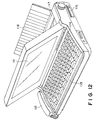
- the above-mentioned information processing machine may be constructed of a integral type with the ink jet printer accommodated therein to improve its portability, as is shown in Fig. 12.
- corresponding reference numerals are given to the parts having the same functions as those shown in Fig. 11.
Landscapes
- Accessory Devices And Overall Control Thereof (AREA)
- Particle Formation And Scattering Control In Inkjet Printers (AREA)
- Ink Jet (AREA)
- Electronic Switches (AREA)
- Common Mechanisms (AREA)
- Printers Or Recording Devices Using Electromagnetic And Radiation Means (AREA)
- Fax Reproducing Arrangements (AREA)
Claims (11)
- Aufzeichnungskopf (41) bei dem eine Vielzahl von auf einem ersten Substrat (24) vorgesehenen Verdrahtungsanschlußflächen (26) und eine entsprechende Vielzahl von auf einem zweiten Substrat (25) vorgesehenen Verdrahtungsanschlußflächen (27) mittels eines elektrisch leitfähigen Blattes (11; 91), das eine Vielzahl von in einem Isolator (12; 93) angeordneten elektrisch leitfähigen Teilen (13; 92A, 92B) aufweist, elektrisch miteinander verbunden sind,
dadurch gekennzeichnet, daß
der Durchmesser und/oder die Verteilungsdichte der elektrisch leitfähigen Teile (13; 92A, 92B) von einem Bereich zu einem anderen unterschiedlich ist. - Aufzeichnungskopf (41) gemäß Patentanspruch 1, wobei der Durchmesser und/oder die Verteilungsdichte der elektrisch leifähigen Teile (13; 92A, 92B) abhängig von dem Durchmesser (l₀) oder der Verteilungsdichte der Verdrahtungsanschlußflächen (26, 27) des ersten und zweiten Substrates (24, 25) ist.
- Aufzeichnungskopf (41) gemäß Patentanspruch 1, wobei der Durchmesser und/oder die Verteilungsdichte der elektrisch leitfähigen Teile (13; 92A, 92B) von dem Betrag des Stromes abhängig ist, der im Betrieb zwischen den entsprechenden Anschlußflächen (26, 27) des ersten und zweiten Substrates (24, 25) fließt.
- Aufzeichnungskopf (41) gemäß einem der vorhergehenden Patentansprüche, wobei der Aufzeichnungskopf (41) von eilnem Vollzeilentyp ist.
- Aufzeichnungskopf (41) gemäß einem der vorhergehenden Patentansprüche, wobei der Aufzeichnungskopf (41) von einem Typ ist, der Tinte unter Verwendung von Wärmeenergie ausstößt und das erste Substrat (24) elektrothermische Energie-Umwandler zum Ausstoßen von Tinte durch Erzeugen von Wärmeenergie aufweist, um in der Tinte ein Phänomen des Filmsiedens zu erzeugen.
- Aufzeichnungskopf gemäß einem der Patentansprüche 1 bis 5, wobei das erste Substrat (24) ein Elementsubstrat ist, auf dem Energie-Erzeugungseinrichtungen zum Ausstoßen von Tinte befestigt sind, und daß zweite Substrat (25) ein Ansteuersubstrat zum Zuführen von Ansteuersignalen zu dem ersten Substrat (24) ist.
- Aufzeichnungsgerät mit:
einem Aufzeichnungskopf (41) gemäß einem der vorhergehenden Patentansprüche; und
Einrichtungen (43₁, 43₂, ) zum Befördern eines Aufzeichnungsmediums (42), auf dem eine Aufzeichnung mittels von dem Aufzeichnungskopf (41) ausgestoßener Tinte durchzuführen ist. - Elektrisch leitfähiges Blatt (11; 91) für einen Aufzeichnungskopf (41), wobei eine Vielzahl von auf einem ersten Substrat (24) vorgesehenen Verdrahtungsanschlußflächen (26) und eine entsprechende Vielzahl von auf einem zweiten Substrat (25) vorgesehenen Verdrahtungsanschlußflächen (27) mittels des elektrisch leitfähigen Blattes (11; 91) elektrisch miteinander verbunden sind, wobei das elektrisch leitfähige Blatt (11; 91) eine Vielzahl elektrisch leitfähiger Teile (13; 92A , 92B) umfaßt, die in einem Isolator (12; 93) angeordnet sind, und
dadurch gekennzeichnet, daß
der Durchmesser und/oder die Verteilungsdichte der elektrisch leitfähigen Teile (13; 92A, 92B) von einem Bereich zu einem anderen unterschiedlich sind. - Elektrisch leitfähiges Blatt (11; 91) für einen Aufzeichnungskopf (41) gemäß Patentanspruch 8, wobei der Durchmesser und/oder die verteilungsdichte der elektrisch leitfähigen Teile (13; 92A, 92B) von dem Durchmesser (l₀) und/oder der Verteilungsdichte der entsprechenden Verdrahtungsanschlußflächen (26, 27) des ersten und zweiten Substrates (24, 25) abhängig sind.
- Elektrisch leitfähiges Blatt (11; 91) für einen Aufzeichnungskopf (41) gemäß Patentanspruch 8, wobei der Durchmesser und/oder die Verteilungsdichte der elektrisch leitfähigen Teile (13; 92A, 92B) von dem zwischen den jeweiligen entsprechenden Anschlußflächen (26, 27) des ersten und zweiten Substrats (24, 25) fließenden Strombetrag abhängig ist.
- Aufzeichnungskopf (41), Aufzeichnungsgerät oder ein elektrisch leitfähiges Blatt gemäß einem der vorhergehenden Ansprüche, wobei der Abstand (L1, L2; L) der Durchmesser, und die Verteilungsdichte der elektrisch leitfähigen Teile (13; 92A, 92B) in jedem entsprechenden Bereich gleichförmig ist.
Applications Claiming Priority (4)
| Application Number | Priority Date | Filing Date | Title |
|---|---|---|---|
| JP29492/90 | 1990-02-13 | ||
| JP2949290 | 1990-02-13 | ||
| JP3017636A JP3029129B2 (ja) | 1990-02-13 | 1991-02-08 | 記録ヘッド用導電シート及びこれを用いた記録ヘッド並びに記録装置 |
| JP17636/91 | 1991-02-08 |
Publications (3)
| Publication Number | Publication Date |
|---|---|
| EP0442706A2 EP0442706A2 (de) | 1991-08-21 |
| EP0442706A3 EP0442706A3 (en) | 1991-10-16 |
| EP0442706B1 true EP0442706B1 (de) | 1995-12-20 |
Family
ID=26354194
Family Applications (1)
| Application Number | Title | Priority Date | Filing Date |
|---|---|---|---|
| EP91301130A Expired - Lifetime EP0442706B1 (de) | 1990-02-13 | 1991-02-12 | Leitfähiges Blatt für Aufzeichnungskopf eines Aufzeichnungsgerätes |
Country Status (6)
| Country | Link |
|---|---|
| US (1) | US5420620A (de) |
| EP (1) | EP0442706B1 (de) |
| JP (1) | JP3029129B2 (de) |
| AT (1) | ATE131780T1 (de) |
| DE (1) | DE69115519T2 (de) |
| ES (1) | ES2082127T3 (de) |
Families Citing this family (10)
| Publication number | Priority date | Publication date | Assignee | Title |
|---|---|---|---|---|
| DE69321349T2 (de) * | 1992-07-03 | 1999-02-25 | Citizen Watch Co., Ltd., Tokio/Tokyo | Tintenstrahldruckkopf |
| EP0644051A1 (de) * | 1993-09-16 | 1995-03-22 | Hewlett-Packard Company | Ein flexibler Zwischenschaltkreis für eine Tintenstrahldruckkartusche, welcher mehrere Öffnungen aufweist |
| US20020055285A1 (en) * | 1999-12-20 | 2002-05-09 | Rambus, Inc. | Chip socket assembly and chip file assembly for semiconductor chips |
| US6113214A (en) * | 1995-06-08 | 2000-09-05 | Canon Kabushiki Kaisha | Ink jet recording head having components made from the same material, recording apparatus using the head, and method for manufacturing such head and ink jet recording apparatus |
| US6024439A (en) * | 1995-09-21 | 2000-02-15 | Canon Kabushiki Kaisha | Ink-jet head having projecting portion |
| KR100284341B1 (ko) * | 1999-03-02 | 2001-03-02 | 김순택 | Ac형 플라즈마 표시 패널의 구동 방법 |
| JP2000331538A (ja) * | 1999-05-17 | 2000-11-30 | Nitto Denko Corp | 異方導電性フィルムおよびその製造方法 |
| US6659591B2 (en) * | 2000-07-10 | 2003-12-09 | Canon Kabushiki Kaisha | Ink jet recording head and producing method for the same |
| US7171748B2 (en) * | 2002-08-30 | 2007-02-06 | Canon Kabushiki Kaisha | Method of manufacturing a liquid jet recording head |
| TWI450237B (zh) * | 2010-01-14 | 2014-08-21 | Wintek Corp | 觸控顯示裝置 |
Family Cites Families (17)
| Publication number | Priority date | Publication date | Assignee | Title |
|---|---|---|---|---|
| US3541222A (en) * | 1969-01-13 | 1970-11-17 | Bunker Ramo | Connector screen for interconnecting adjacent surfaces of laminar circuits and method of making |
| US4209481A (en) * | 1976-04-19 | 1980-06-24 | Toray Industries, Inc. | Process for producing an anisotropically electroconductive sheet |
| CA1127227A (en) * | 1977-10-03 | 1982-07-06 | Ichiro Endo | Liquid jet recording process and apparatus therefor |
| US4330787A (en) * | 1978-10-31 | 1982-05-18 | Canon Kabushiki Kaisha | Liquid jet recording device |
| US4345262A (en) * | 1979-02-19 | 1982-08-17 | Canon Kabushiki Kaisha | Ink jet recording method |
| US4463359A (en) * | 1979-04-02 | 1984-07-31 | Canon Kabushiki Kaisha | Droplet generating method and apparatus thereof |
| US4313124A (en) * | 1979-05-18 | 1982-01-26 | Canon Kabushiki Kaisha | Liquid jet recording process and liquid jet recording head |
| US4558333A (en) * | 1981-07-09 | 1985-12-10 | Canon Kabushiki Kaisha | Liquid jet recording head |
| JPH0825272B2 (ja) * | 1984-07-03 | 1996-03-13 | キヤノン株式会社 | 液体噴射記録ヘッド |
| EP0854506A3 (de) * | 1987-03-04 | 1999-03-31 | Canon Kabushiki Kaisha | Elektrisches Verbindungsteil und elektrisches Schaltungsteil |
| JP2528112B2 (ja) * | 1987-03-13 | 1996-08-28 | キヤノン株式会社 | 電気的接続部材及びそれを用いた電気回路部材 |
| JPS63299065A (ja) * | 1987-05-29 | 1988-12-06 | Toshiba Corp | 電子部品の接続方法 |
| US5197892A (en) * | 1988-05-31 | 1993-03-30 | Canon Kabushiki Kaisha | Electric circuit device having an electric connecting member and electric circuit components |
| JPH01302830A (ja) * | 1988-05-31 | 1989-12-06 | Canon Inc | 電気回路装置 |
| FR2634340B1 (fr) * | 1988-07-13 | 1994-06-17 | Thomson Csf | Dispositif d'interconnexion entre un circuit integre et un circuit electrique, application du dispositif a la connexion d'un circuit integre notamment a un circuit imprime, et procede de fabrication du dispositif |
| US4887098A (en) * | 1988-11-25 | 1989-12-12 | Xerox Corporation | Thermal ink jet printer having printhead transducers with multilevelinterconnections |
| US5049084A (en) * | 1989-12-05 | 1991-09-17 | Rogers Corporation | Electrical circuit board interconnect |
-
1991
- 1991-02-08 JP JP3017636A patent/JP3029129B2/ja not_active Expired - Fee Related
- 1991-02-12 ES ES91301130T patent/ES2082127T3/es not_active Expired - Lifetime
- 1991-02-12 EP EP91301130A patent/EP0442706B1/de not_active Expired - Lifetime
- 1991-02-12 DE DE69115519T patent/DE69115519T2/de not_active Expired - Fee Related
- 1991-02-12 AT AT91301130T patent/ATE131780T1/de active
-
1993
- 1993-02-16 US US08/022,436 patent/US5420620A/en not_active Expired - Fee Related
Also Published As
| Publication number | Publication date |
|---|---|
| ES2082127T3 (es) | 1996-03-16 |
| US5420620A (en) | 1995-05-30 |
| ATE131780T1 (de) | 1996-01-15 |
| JP3029129B2 (ja) | 2000-04-04 |
| DE69115519D1 (de) | 1996-02-01 |
| EP0442706A3 (en) | 1991-10-16 |
| EP0442706A2 (de) | 1991-08-21 |
| JPH04211947A (ja) | 1992-08-03 |
| DE69115519T2 (de) | 1996-05-15 |
Similar Documents
| Publication | Publication Date | Title |
|---|---|---|
| US5182580A (en) | Ink jet recording apparatus with abnormal state detection | |
| US5448274A (en) | Ink jet recording apparatus and carriage mechanism therefor | |
| EP0475696B1 (de) | Verfahren und Gerät zur seriellen Aufzeichnung | |
| EP0442706B1 (de) | Leitfähiges Blatt für Aufzeichnungskopf eines Aufzeichnungsgerätes | |
| EP0581298A2 (de) | Farbstrahlaufzeichnungskopf, Kassette für einen Tintenstrahlaufzeichnungskopf, Aufzeichnungsgerät damit versehen und Herstellungsverfahren des Kopfes | |
| JP3227268B2 (ja) | インクジェット記録装置およびインクジェット記録方法 | |
| EP0927636B1 (de) | Tintenstrahlaufzeichnungssystem | |
| JPH02151445A (ja) | 改良されたサーマルインク印刷カートリッジ組立体 | |
| JPH07144419A (ja) | インクジェット記録装置 | |
| JP3337792B2 (ja) | データ処理装置及び記録装置及びデータ処理方法 | |
| EP0547596B1 (de) | Tintenstrahlaufzeichnungskopf, Kassette für einen Tintenstrahlaufzeichnungskopf, und Aufzeichnungsgerät damit versehen | |
| US5701147A (en) | Ink jet head and ink jet apparatus using same | |
| JPH09314833A (ja) | インクジェットプリンタヘッド | |
| CN113211985A (zh) | 热气泡喷墨头装置 | |
| EP0769378B1 (de) | Aufzeichnungskopf, Aufzeichnungskassette und Aufzeichnungsvorrichtung | |
| JP3313884B2 (ja) | インクジェット記録方法 | |
| JP3126537B2 (ja) | インクジェット記録方法およびその装置 | |
| JPH06126943A (ja) | インクジェット記録ヘッドおよびインクジェット記録装置 | |
| JPH05325729A (ja) | 記録装置 | |
| JPH07256882A (ja) | インクジェット記録ヘッド、その製造方法及び該記録ヘッドを具備する記録装置 | |
| JP2898118B2 (ja) | インクジェット記録装置および該装置を用いる電子機器 | |
| JPH10157117A (ja) | インクジェット記録ヘッド、インクジェット記録装置、および情報処理装置 | |
| JPH091803A (ja) | インクジェットヘッド、該インクジェットヘッドを用いたヘッドカートリッジ、インクジェット記録装置およびヘッドキット | |
| JPH05330029A (ja) | インクジェットカートリッジ | |
| JPH05169662A (ja) | インクジェット記録ヘッド、インクジェット記録ヘッドカートリッジ及びこれを搭載した記録装置 |
Legal Events
| Date | Code | Title | Description |
|---|---|---|---|
| PUAI | Public reference made under article 153(3) epc to a published international application that has entered the european phase |
Free format text: ORIGINAL CODE: 0009012 |
|
| AK | Designated contracting states |
Kind code of ref document: A2 Designated state(s): AT BE CH DE DK ES FR GB GR IT LI LU NL SE |
|
| PUAL | Search report despatched |
Free format text: ORIGINAL CODE: 0009013 |
|
| AK | Designated contracting states |
Kind code of ref document: A3 Designated state(s): AT BE CH DE DK ES FR GB GR IT LI LU NL SE |
|
| 17P | Request for examination filed |
Effective date: 19920309 |
|
| 17Q | First examination report despatched |
Effective date: 19931029 |
|
| GRAA | (expected) grant |
Free format text: ORIGINAL CODE: 0009210 |
|
| AK | Designated contracting states |
Kind code of ref document: B1 Designated state(s): AT BE CH DE DK ES FR GB GR IT LI LU NL SE |
|
| PG25 | Lapsed in a contracting state [announced via postgrant information from national office to epo] |
Ref country code: LI Free format text: LAPSE BECAUSE OF FAILURE TO SUBMIT A TRANSLATION OF THE DESCRIPTION OR TO PAY THE FEE WITHIN THE PRESCRIBED TIME-LIMIT Effective date: 19951220 Ref country code: GR Free format text: LAPSE BECAUSE OF FAILURE TO SUBMIT A TRANSLATION OF THE DESCRIPTION OR TO PAY THE FEE WITHIN THE PRESCRIBED TIME-LIMIT Effective date: 19951220 Ref country code: DK Effective date: 19951220 Ref country code: CH Free format text: LAPSE BECAUSE OF FAILURE TO SUBMIT A TRANSLATION OF THE DESCRIPTION OR TO PAY THE FEE WITHIN THE PRESCRIBED TIME-LIMIT Effective date: 19951220 Ref country code: BE Effective date: 19951220 Ref country code: AT Effective date: 19951220 |
|
| REF | Corresponds to: |
Ref document number: 131780 Country of ref document: AT Date of ref document: 19960115 Kind code of ref document: T |
|
| REF | Corresponds to: |
Ref document number: 69115519 Country of ref document: DE Date of ref document: 19960201 |
|
| PG25 | Lapsed in a contracting state [announced via postgrant information from national office to epo] |
Ref country code: LU Free format text: LAPSE BECAUSE OF NON-PAYMENT OF DUE FEES Effective date: 19960229 |
|
| ET | Fr: translation filed | ||
| ITF | It: translation for a ep patent filed | ||
| REG | Reference to a national code |
Ref country code: ES Ref legal event code: FG2A Ref document number: 2082127 Country of ref document: ES Kind code of ref document: T3 |
|
| PG25 | Lapsed in a contracting state [announced via postgrant information from national office to epo] |
Ref country code: SE Effective date: 19960320 |
|
| PLBE | No opposition filed within time limit |
Free format text: ORIGINAL CODE: 0009261 |
|
| STAA | Information on the status of an ep patent application or granted ep patent |
Free format text: STATUS: NO OPPOSITION FILED WITHIN TIME LIMIT |
|
| 26N | No opposition filed | ||
| REG | Reference to a national code |
Ref country code: GB Ref legal event code: IF02 |
|
| PGFP | Annual fee paid to national office [announced via postgrant information from national office to epo] |
Ref country code: GB Payment date: 20050131 Year of fee payment: 15 |
|
| PGFP | Annual fee paid to national office [announced via postgrant information from national office to epo] |
Ref country code: ES Payment date: 20050209 Year of fee payment: 15 |
|
| PGFP | Annual fee paid to national office [announced via postgrant information from national office to epo] |
Ref country code: NL Payment date: 20050214 Year of fee payment: 15 |
|
| PGFP | Annual fee paid to national office [announced via postgrant information from national office to epo] |
Ref country code: FR Payment date: 20050216 Year of fee payment: 15 |
|
| PGFP | Annual fee paid to national office [announced via postgrant information from national office to epo] |
Ref country code: DE Payment date: 20050420 Year of fee payment: 15 |
|
| PG25 | Lapsed in a contracting state [announced via postgrant information from national office to epo] |
Ref country code: GB Free format text: LAPSE BECAUSE OF NON-PAYMENT OF DUE FEES Effective date: 20060212 |
|
| PG25 | Lapsed in a contracting state [announced via postgrant information from national office to epo] |
Ref country code: ES Free format text: LAPSE BECAUSE OF NON-PAYMENT OF DUE FEES Effective date: 20060213 |
|
| PGFP | Annual fee paid to national office [announced via postgrant information from national office to epo] |
Ref country code: IT Payment date: 20060228 Year of fee payment: 16 |
|
| PG25 | Lapsed in a contracting state [announced via postgrant information from national office to epo] |
Ref country code: NL Free format text: LAPSE BECAUSE OF NON-PAYMENT OF DUE FEES Effective date: 20060901 Ref country code: DE Free format text: LAPSE BECAUSE OF NON-PAYMENT OF DUE FEES Effective date: 20060901 |
|
| GBPC | Gb: european patent ceased through non-payment of renewal fee |
Effective date: 20060212 |
|
| NLV4 | Nl: lapsed or anulled due to non-payment of the annual fee |
Effective date: 20060901 |
|
| REG | Reference to a national code |
Ref country code: FR Ref legal event code: ST Effective date: 20061031 |
|
| REG | Reference to a national code |
Ref country code: ES Ref legal event code: FD2A Effective date: 20060213 |
|
| PG25 | Lapsed in a contracting state [announced via postgrant information from national office to epo] |
Ref country code: FR Free format text: LAPSE BECAUSE OF NON-PAYMENT OF DUE FEES Effective date: 20060228 |
|
| PG25 | Lapsed in a contracting state [announced via postgrant information from national office to epo] |
Ref country code: IT Free format text: LAPSE BECAUSE OF NON-PAYMENT OF DUE FEES Effective date: 20070212 |