EP0445761B1 - Génération de colorant in situ pour l'impression thermique par transfert de colorant - Google Patents
Génération de colorant in situ pour l'impression thermique par transfert de colorant Download PDFInfo
- Publication number
- EP0445761B1 EP0445761B1 EP91103388A EP91103388A EP0445761B1 EP 0445761 B1 EP0445761 B1 EP 0445761B1 EP 91103388 A EP91103388 A EP 91103388A EP 91103388 A EP91103388 A EP 91103388A EP 0445761 B1 EP0445761 B1 EP 0445761B1
- Authority
- EP
- European Patent Office
- Prior art keywords
- substituted
- unsubstituted
- carbon atoms
- electrophile
- alkenyl
- Prior art date
- Legal status (The legal status is an assumption and is not a legal conclusion. Google has not performed a legal analysis and makes no representation as to the accuracy of the status listed.)
- Expired - Lifetime
Links
- 238000011065 in-situ storage Methods 0.000 title description 7
- 238000010023 transfer printing Methods 0.000 title description 2
- 239000012039 electrophile Substances 0.000 claims description 81
- 150000001875 compounds Chemical class 0.000 claims description 65
- 239000000975 dye Substances 0.000 claims description 64
- -1 cyano, benzoxazolyl Chemical group 0.000 claims description 31
- 125000004432 carbon atom Chemical group C* 0.000 claims description 29
- 125000003118 aryl group Chemical group 0.000 claims description 24
- 229910052739 hydrogen Inorganic materials 0.000 claims description 23
- 239000001257 hydrogen Substances 0.000 claims description 23
- 125000003342 alkenyl group Chemical group 0.000 claims description 21
- 125000000217 alkyl group Chemical group 0.000 claims description 21
- 229910052736 halogen Inorganic materials 0.000 claims description 15
- 150000002367 halogens Chemical class 0.000 claims description 15
- 125000004429 atom Chemical group 0.000 claims description 10
- 125000002915 carbonyl group Chemical group [*:2]C([*:1])=O 0.000 claims description 10
- 125000004435 hydrogen atom Chemical group [H]* 0.000 claims description 9
- 238000000034 method Methods 0.000 claims description 8
- UFHFLCQGNIYNRP-UHFFFAOYSA-N Hydrogen Chemical compound [H][H] UFHFLCQGNIYNRP-UHFFFAOYSA-N 0.000 claims description 6
- 229910052760 oxygen Inorganic materials 0.000 claims description 6
- 125000004423 acyloxy group Chemical group 0.000 claims description 5
- 125000005278 alkyl sulfonyloxy group Chemical group 0.000 claims description 5
- 150000004982 aromatic amines Chemical class 0.000 claims description 5
- 125000005279 aryl sulfonyloxy group Chemical group 0.000 claims description 5
- 125000000449 nitro group Chemical group [O-][N+](*)=O 0.000 claims description 5
- 230000008569 process Effects 0.000 claims description 5
- 125000002837 carbocyclic group Chemical group 0.000 claims description 4
- 125000004093 cyano group Chemical group *C#N 0.000 claims description 3
- 125000004433 nitrogen atom Chemical group N* 0.000 claims description 3
- 125000004430 oxygen atom Chemical group O* 0.000 claims description 3
- 125000004434 sulfur atom Chemical group 0.000 claims description 3
- 150000002431 hydrogen Chemical class 0.000 claims 10
- 125000003968 arylidene group Chemical group [H]C(c)=* 0.000 claims 4
- 102000003728 Peroxisome Proliferator-Activated Receptors Human genes 0.000 claims 1
- 108090000029 Peroxisome Proliferator-Activated Receptors Proteins 0.000 claims 1
- 239000011230 binding agent Substances 0.000 description 22
- 239000000463 material Substances 0.000 description 10
- XEKOWRVHYACXOJ-UHFFFAOYSA-N Ethyl acetate Chemical compound CCOC(C)=O XEKOWRVHYACXOJ-UHFFFAOYSA-N 0.000 description 9
- LRHPLDYGYMQRHN-UHFFFAOYSA-N N-Butanol Chemical compound CCCCO LRHPLDYGYMQRHN-UHFFFAOYSA-N 0.000 description 9
- 239000004417 polycarbonate Substances 0.000 description 9
- 229920000515 polycarbonate Polymers 0.000 description 9
- 238000007639 printing Methods 0.000 description 8
- 229920008347 Cellulose acetate propionate Polymers 0.000 description 7
- YMWUJEATGCHHMB-UHFFFAOYSA-N Dichloromethane Chemical compound ClCCl YMWUJEATGCHHMB-UHFFFAOYSA-N 0.000 description 6
- 229920001971 elastomer Polymers 0.000 description 6
- 238000003384 imaging method Methods 0.000 description 6
- 229920002301 cellulose acetate Polymers 0.000 description 5
- 230000001050 lubricating effect Effects 0.000 description 5
- 239000000123 paper Substances 0.000 description 5
- 229920000728 polyester Polymers 0.000 description 5
- 229920000139 polyethylene terephthalate Polymers 0.000 description 5
- 239000005020 polyethylene terephthalate Substances 0.000 description 5
- YKYONYBAUNKHLG-UHFFFAOYSA-N propyl acetate Chemical compound CCCOC(C)=O YKYONYBAUNKHLG-UHFFFAOYSA-N 0.000 description 5
- 238000007651 thermal printing Methods 0.000 description 5
- 150000004646 arylidenes Chemical group 0.000 description 4
- 229920002678 cellulose Polymers 0.000 description 4
- 239000011877 solvent mixture Substances 0.000 description 4
- LYCAIKOWRPUZTN-UHFFFAOYSA-N Ethylene glycol Chemical compound OCCO LYCAIKOWRPUZTN-UHFFFAOYSA-N 0.000 description 3
- KFZMGEQAYNKOFK-UHFFFAOYSA-N Isopropanol Chemical compound CC(C)O KFZMGEQAYNKOFK-UHFFFAOYSA-N 0.000 description 3
- YXFVVABEGXRONW-UHFFFAOYSA-N Toluene Chemical compound CC1=CC=CC=C1 YXFVVABEGXRONW-UHFFFAOYSA-N 0.000 description 3
- 230000015572 biosynthetic process Effects 0.000 description 3
- 239000011248 coating agent Substances 0.000 description 3
- 238000000576 coating method Methods 0.000 description 3
- 229920002285 poly(styrene-co-acrylonitrile) Polymers 0.000 description 3
- 125000000391 vinyl group Chemical group [H]C([*])=C([H])[H] 0.000 description 3
- 229920002554 vinyl polymer Polymers 0.000 description 3
- ZWEHNKRNPOVVGH-UHFFFAOYSA-N 2-Butanone Chemical compound CCC(C)=O ZWEHNKRNPOVVGH-UHFFFAOYSA-N 0.000 description 2
- 229940126062 Compound A Drugs 0.000 description 2
- NLDMNSXOCDLTTB-UHFFFAOYSA-N Heterophylliin A Natural products O1C2COC(=O)C3=CC(O)=C(O)C(O)=C3C3=C(O)C(O)=C(O)C=C3C(=O)OC2C(OC(=O)C=2C=C(O)C(O)=C(O)C=2)C(O)C1OC(=O)C1=CC(O)=C(O)C(O)=C1 NLDMNSXOCDLTTB-UHFFFAOYSA-N 0.000 description 2
- 239000004642 Polyimide Substances 0.000 description 2
- KKEYFWRCBNTPAC-UHFFFAOYSA-N Terephthalic acid Chemical compound OC(=O)C1=CC=C(C(O)=O)C=C1 KKEYFWRCBNTPAC-UHFFFAOYSA-N 0.000 description 2
- GWEVSGVZZGPLCZ-UHFFFAOYSA-N Titan oxide Chemical compound O=[Ti]=O GWEVSGVZZGPLCZ-UHFFFAOYSA-N 0.000 description 2
- 125000002777 acetyl group Chemical group [H]C([H])([H])C(*)=O 0.000 description 2
- 230000004888 barrier function Effects 0.000 description 2
- 230000008901 benefit Effects 0.000 description 2
- IISBACLAFKSPIT-UHFFFAOYSA-N bisphenol A Chemical compound C=1C=C(O)C=CC=1C(C)(C)C1=CC=C(O)C=C1 IISBACLAFKSPIT-UHFFFAOYSA-N 0.000 description 2
- YHWCPXVTRSHPNY-UHFFFAOYSA-N butan-1-olate;titanium(4+) Chemical compound [Ti+4].CCCC[O-].CCCC[O-].CCCC[O-].CCCC[O-] YHWCPXVTRSHPNY-UHFFFAOYSA-N 0.000 description 2
- 239000001913 cellulose Substances 0.000 description 2
- 229920006217 cellulose acetate butyrate Polymers 0.000 description 2
- 238000004040 coloring Methods 0.000 description 2
- BGTOWKSIORTVQH-UHFFFAOYSA-N cyclopentanone Chemical compound O=C1CCCC1 BGTOWKSIORTVQH-UHFFFAOYSA-N 0.000 description 2
- 238000010438 heat treatment Methods 0.000 description 2
- 125000000623 heterocyclic group Chemical group 0.000 description 2
- 239000000314 lubricant Substances 0.000 description 2
- 239000000203 mixture Substances 0.000 description 2
- 239000000178 monomer Substances 0.000 description 2
- 229920001610 polycaprolactone Polymers 0.000 description 2
- 229920000570 polyether Polymers 0.000 description 2
- 229920001721 polyimide Polymers 0.000 description 2
- 229920000642 polymer Polymers 0.000 description 2
- 229920006324 polyoxymethylene Polymers 0.000 description 2
- 229920002223 polystyrene Polymers 0.000 description 2
- 125000001501 propionyl group Chemical group O=C([*])C([H])([H])C([H])([H])[H] 0.000 description 2
- 239000007787 solid Substances 0.000 description 2
- 229910052719 titanium Inorganic materials 0.000 description 2
- 239000010936 titanium Substances 0.000 description 2
- AFABGHUZZDYHJO-UHFFFAOYSA-N 2-Methylpentane Chemical compound CCCC(C)C AFABGHUZZDYHJO-UHFFFAOYSA-N 0.000 description 1
- WTPYFJNYAMXZJG-UHFFFAOYSA-N 2-[4-(2-hydroxyethoxy)phenoxy]ethanol Chemical compound OCCOC1=CC=C(OCCO)C=C1 WTPYFJNYAMXZJG-UHFFFAOYSA-N 0.000 description 1
- 229920002284 Cellulose triacetate Polymers 0.000 description 1
- ZZSNKZQZMQGXPY-UHFFFAOYSA-N Ethyl cellulose Chemical compound CCOCC1OC(OC)C(OCC)C(OCC)C1OC1C(O)C(O)C(OC)C(CO)O1 ZZSNKZQZMQGXPY-UHFFFAOYSA-N 0.000 description 1
- 239000001856 Ethyl cellulose Substances 0.000 description 1
- YCKRFDGAMUMZLT-UHFFFAOYSA-N Fluorine atom Chemical compound [F] YCKRFDGAMUMZLT-UHFFFAOYSA-N 0.000 description 1
- 239000000020 Nitrocellulose Substances 0.000 description 1
- 239000002033 PVDF binder Substances 0.000 description 1
- 229930040373 Paraformaldehyde Natural products 0.000 description 1
- ALQSHHUCVQOPAS-UHFFFAOYSA-N Pentane-1,5-diol Chemical compound OCCCCCO ALQSHHUCVQOPAS-UHFFFAOYSA-N 0.000 description 1
- ISWSIDIOOBJBQZ-UHFFFAOYSA-N Phenol Chemical compound OC1=CC=CC=C1 ISWSIDIOOBJBQZ-UHFFFAOYSA-N 0.000 description 1
- 239000004952 Polyamide Substances 0.000 description 1
- 239000004698 Polyethylene Substances 0.000 description 1
- 239000004743 Polypropylene Substances 0.000 description 1
- 239000004793 Polystyrene Substances 0.000 description 1
- 229920000690 Tyvek Polymers 0.000 description 1
- 239000004775 Tyvek Substances 0.000 description 1
- NNLVGZFZQQXQNW-ADJNRHBOSA-N [(2r,3r,4s,5r,6s)-4,5-diacetyloxy-3-[(2s,3r,4s,5r,6r)-3,4,5-triacetyloxy-6-(acetyloxymethyl)oxan-2-yl]oxy-6-[(2r,3r,4s,5r,6s)-4,5,6-triacetyloxy-2-(acetyloxymethyl)oxan-3-yl]oxyoxan-2-yl]methyl acetate Chemical compound O([C@@H]1O[C@@H]([C@H]([C@H](OC(C)=O)[C@H]1OC(C)=O)O[C@H]1[C@@H]([C@@H](OC(C)=O)[C@H](OC(C)=O)[C@@H](COC(C)=O)O1)OC(C)=O)COC(=O)C)[C@@H]1[C@@H](COC(C)=O)O[C@@H](OC(C)=O)[C@H](OC(C)=O)[C@H]1OC(C)=O NNLVGZFZQQXQNW-ADJNRHBOSA-N 0.000 description 1
- FJWGYAHXMCUOOM-QHOUIDNNSA-N [(2s,3r,4s,5r,6r)-2-[(2r,3r,4s,5r,6s)-4,5-dinitrooxy-2-(nitrooxymethyl)-6-[(2r,3r,4s,5r,6s)-4,5,6-trinitrooxy-2-(nitrooxymethyl)oxan-3-yl]oxyoxan-3-yl]oxy-3,5-dinitrooxy-6-(nitrooxymethyl)oxan-4-yl] nitrate Chemical compound O([C@@H]1O[C@@H]([C@H]([C@H](O[N+]([O-])=O)[C@H]1O[N+]([O-])=O)O[C@H]1[C@@H]([C@@H](O[N+]([O-])=O)[C@H](O[N+]([O-])=O)[C@@H](CO[N+]([O-])=O)O1)O[N+]([O-])=O)CO[N+](=O)[O-])[C@@H]1[C@@H](CO[N+]([O-])=O)O[C@@H](O[N+]([O-])=O)[C@H](O[N+]([O-])=O)[C@H]1O[N+]([O-])=O FJWGYAHXMCUOOM-QHOUIDNNSA-N 0.000 description 1
- 238000010521 absorption reaction Methods 0.000 description 1
- GAMPNQJDUFQVQO-UHFFFAOYSA-N acetic acid;phthalic acid Chemical compound CC(O)=O.OC(=O)C1=CC=CC=C1C(O)=O GAMPNQJDUFQVQO-UHFFFAOYSA-N 0.000 description 1
- 125000005907 alkyl ester group Chemical group 0.000 description 1
- QVQLCTNNEUAWMS-UHFFFAOYSA-N barium oxide Chemical compound [Ba]=O QVQLCTNNEUAWMS-UHFFFAOYSA-N 0.000 description 1
- 229910001864 baryta Inorganic materials 0.000 description 1
- 235000013871 bee wax Nutrition 0.000 description 1
- 239000012166 beeswax Substances 0.000 description 1
- 230000008859 change Effects 0.000 description 1
- 238000006243 chemical reaction Methods 0.000 description 1
- 239000003153 chemical reaction reagent Substances 0.000 description 1
- 239000000084 colloidal system Substances 0.000 description 1
- 239000003086 colorant Substances 0.000 description 1
- 150000002009 diols Chemical class 0.000 description 1
- 208000028659 discharge Diseases 0.000 description 1
- 229920001249 ethyl cellulose Polymers 0.000 description 1
- 235000019325 ethyl cellulose Nutrition 0.000 description 1
- 238000011156 evaluation Methods 0.000 description 1
- 238000001704 evaporation Methods 0.000 description 1
- 229910052731 fluorine Inorganic materials 0.000 description 1
- 239000011737 fluorine Substances 0.000 description 1
- 239000011086 glassine Substances 0.000 description 1
- 229920001477 hydrophilic polymer Polymers 0.000 description 1
- 125000002887 hydroxy group Chemical group [H]O* 0.000 description 1
- 239000010687 lubricating oil Substances 0.000 description 1
- VLKZOEOYAKHREP-UHFFFAOYSA-N methyl pentane Natural products CCCCCC VLKZOEOYAKHREP-UHFFFAOYSA-N 0.000 description 1
- 229920001220 nitrocellulos Polymers 0.000 description 1
- 239000003921 oil Substances 0.000 description 1
- 239000002245 particle Substances 0.000 description 1
- 150000003014 phosphoric acid esters Chemical class 0.000 description 1
- 229920002492 poly(sulfone) Polymers 0.000 description 1
- 229920002647 polyamide Polymers 0.000 description 1
- 229920005668 polycarbonate resin Polymers 0.000 description 1
- 239000004431 polycarbonate resin Substances 0.000 description 1
- 229920006393 polyether sulfone Polymers 0.000 description 1
- 229920001601 polyetherimide Polymers 0.000 description 1
- 229920000573 polyethylene Polymers 0.000 description 1
- 229920001223 polyethylene glycol Polymers 0.000 description 1
- 229920000098 polyolefin Polymers 0.000 description 1
- 229920006380 polyphenylene oxide Polymers 0.000 description 1
- 229920001155 polypropylene Polymers 0.000 description 1
- 229920001343 polytetrafluoroethylene Polymers 0.000 description 1
- 229920002635 polyurethane Polymers 0.000 description 1
- 239000004814 polyurethane Substances 0.000 description 1
- 239000011118 polyvinyl acetate Substances 0.000 description 1
- 229920002689 polyvinyl acetate Polymers 0.000 description 1
- 229920000915 polyvinyl chloride Polymers 0.000 description 1
- 239000004800 polyvinyl chloride Substances 0.000 description 1
- 229920002981 polyvinylidene fluoride Polymers 0.000 description 1
- 229940090181 propyl acetate Drugs 0.000 description 1
- 229920005989 resin Polymers 0.000 description 1
- 239000011347 resin Substances 0.000 description 1
- 230000004044 response Effects 0.000 description 1
- 230000000717 retained effect Effects 0.000 description 1
- 238000000926 separation method Methods 0.000 description 1
- 229920002545 silicone oil Polymers 0.000 description 1
- 230000003595 spectral effect Effects 0.000 description 1
- 125000001424 substituent group Chemical group 0.000 description 1
- 239000004094 surface-active agent Substances 0.000 description 1
- 238000001931 thermography Methods 0.000 description 1
- 239000004408 titanium dioxide Substances 0.000 description 1
- 238000002604 ultrasonography Methods 0.000 description 1
- NQPDZGIKBAWPEJ-UHFFFAOYSA-N valeric acid Chemical compound CCCCC(O)=O NQPDZGIKBAWPEJ-UHFFFAOYSA-N 0.000 description 1
- QYSXJUFSXHHAJI-YRZJJWOYSA-N vitamin D3 Chemical compound C1(/[C@@H]2CC[C@@H]([C@]2(CCC1)C)[C@H](C)CCCC(C)C)=C\C=C1\C[C@@H](O)CCC1=C QYSXJUFSXHHAJI-YRZJJWOYSA-N 0.000 description 1
- 239000012463 white pigment Substances 0.000 description 1
Classifications
-
- B—PERFORMING OPERATIONS; TRANSPORTING
- B41—PRINTING; LINING MACHINES; TYPEWRITERS; STAMPS
- B41M—PRINTING, DUPLICATING, MARKING, OR COPYING PROCESSES; COLOUR PRINTING
- B41M5/00—Duplicating or marking methods; Sheet materials for use therein
- B41M5/26—Thermography ; Marking by high energetic means, e.g. laser otherwise than by burning, and characterised by the material used
- B41M5/382—Contact thermal transfer or sublimation processes
- B41M5/385—Contact thermal transfer or sublimation processes characterised by the transferable dyes or pigments
-
- B—PERFORMING OPERATIONS; TRANSPORTING
- B41—PRINTING; LINING MACHINES; TYPEWRITERS; STAMPS
- B41M—PRINTING, DUPLICATING, MARKING, OR COPYING PROCESSES; COLOUR PRINTING
- B41M5/00—Duplicating or marking methods; Sheet materials for use therein
- B41M5/26—Thermography ; Marking by high energetic means, e.g. laser otherwise than by burning, and characterised by the material used
- B41M5/382—Contact thermal transfer or sublimation processes
- B41M5/385—Contact thermal transfer or sublimation processes characterised by the transferable dyes or pigments
- B41M5/3854—Dyes containing one or more acyclic carbon-to-carbon double bonds, e.g., di- or tri-cyanovinyl, methine
-
- Y—GENERAL TAGGING OF NEW TECHNOLOGICAL DEVELOPMENTS; GENERAL TAGGING OF CROSS-SECTIONAL TECHNOLOGIES SPANNING OVER SEVERAL SECTIONS OF THE IPC; TECHNICAL SUBJECTS COVERED BY FORMER USPC CROSS-REFERENCE ART COLLECTIONS [XRACs] AND DIGESTS
- Y10—TECHNICAL SUBJECTS COVERED BY FORMER USPC
- Y10S—TECHNICAL SUBJECTS COVERED BY FORMER USPC CROSS-REFERENCE ART COLLECTIONS [XRACs] AND DIGESTS
- Y10S428/00—Stock material or miscellaneous articles
- Y10S428/913—Material designed to be responsive to temperature, light, moisture
-
- Y—GENERAL TAGGING OF NEW TECHNOLOGICAL DEVELOPMENTS; GENERAL TAGGING OF CROSS-SECTIONAL TECHNOLOGIES SPANNING OVER SEVERAL SECTIONS OF THE IPC; TECHNICAL SUBJECTS COVERED BY FORMER USPC CROSS-REFERENCE ART COLLECTIONS [XRACs] AND DIGESTS
- Y10—TECHNICAL SUBJECTS COVERED BY FORMER USPC
- Y10S—TECHNICAL SUBJECTS COVERED BY FORMER USPC CROSS-REFERENCE ART COLLECTIONS [XRACs] AND DIGESTS
- Y10S428/00—Stock material or miscellaneous articles
- Y10S428/914—Transfer or decalcomania
Definitions
- This invention relates to receiving and donor elements used in thermal transfer printing, and more particularly to the use of reactive compounds (electrophiles and couplers) for in situ dye generation in a thermal transfer system.
- thermal transfer systems have been developed to obtain prints from pictures which have been generated electronically from a color video camera.
- an electronic picture is first subjected to color separation by color filters.
- the respective color-separated images are then converted into electrical signals.
- These signals are then operated on to produce cyan, magenta and yellow electrical signals.
- These signals are then transmitted to a thermal printer.
- a cyan, magenta or yellow dye-donor element is placed face-to-face with a dye-receiving element.
- the two are then inserted between a thermal printing head and a platen roller.
- a line-type thermal printing head is used to apply heat from the back of the dye-donor sheet.
- the thermal printing head has many heating elements and is heated up sequentially in response to the cyan, magenta and yellow signals. The process is then repeated for the other two colors. A color hard copy is thus obtained which corresponds to the original picture viewed on a screen. Further details of this process and an apparatus for carrying it out are contained in U.S. Patent No. 4,621,271 by Brownstein entitled “Apparatus and Method For Controlling A Thermal Printer Apparatus,” issued November 4, 1986.
- the thermal transfer systems described above routinely use the imagewise transfer of a preformed dye from a dye-donor element to a dye-receiving element.
- One of the problems in selecting dyes for such systems is obtaining good transfer efficiency to produce high maximum density.
- Preformed dye molecules of high molecular weight require large amounts of energy for sufficient transfers.
- U.S. Patent No. 4,824,822 of Yamamoto et al discloses a thermosensitive recording method comprising subliming or evaporating a compound A and/or a compound B onto a recording sheet and then reacting compounds A and B together on the recording sheet in order to form coloring matter in situ on the recording sheet.
- Examples of compound B are aromatic amines, and examples of compound A are materials forming free radicals. These compounds react together upon exposure to light to form coloring matter. While this system may require less energy to transfer compounds A and/or B compared to transfer of a preformed dye, the chemistry used requires the additional time, expense and inconvenience of a light exposure step.
- Leuco dyes generally have nearly the same molecular weight as the resulting colored dye. Therefore, no energy savings is achieved by transferring a leuco dye compared to a preformed dye. Also, leuco dyes are generally capable of forming only a single dye hue, thus limiting their use in forming multi-color images.
- thermal dye transfer system having minimum energy requirements, which would also allow for the formation of multi-color images, and also require a minimum number of steps.
- a dye image recording element comprising a support bearing an electrophile capable of reacting with a coupler compound to form an arylidene dye, the electrophile having the following structure: wherein
- the X substituent of such compounds is chosen to be reactive with an active hydrogen atom of a preselected coupler compound and to split-off the electrophile when it and the coupler are reacted together.
- the remaining portion of the electrophile combines with the coupler compound at its active hydrogen position to form a resulting arylidene dye.
- the dye image recording elements of the invention comprising the above-defined electrophiles may take the form of a donor element or a receiver element.
- electrophiles in a donor element may be imagewise transferred to a receiving element containing coupler compounds by imagewise heating the donor element, and reacted together with the coupler compounds to form a dye image.
- coupler compounds may be imagewise transferred from a donor element to a receiving element containing electrophiles.
- the electrophiles are sufficiently reactive with the couplers described below such that an additional light exposure step is not required after bringing the electrophile and coupler together to react to form a dye.
- a single coupler may be reacted with different electrophiles to form dyes of different hues.
- a single electrophile may be reacted with different couplers to form dyes of different hues.
- a further embodiment of the invention comprises a dye image recording assemblage comprising a first element comprising a support bearing a preselected coupler compound, and a second element comprising a support bearing an electrophile as defined above.
- the first and second elements of the assemblage may be either a receiving element and a donor element, respectively, or a donor element and a receiving element.
- both the electrophiles and coupler compounds may be present in separate adjacent areas of a donor element.
- a dye image may then be formed by sequentially transferring the electrophiles and coupler compounds from the donor element to a receiving element where they are reacted together to form a dye image.
- At least one of the electrophile and the coupler compound is transferred imagewise, while the other may be transferred either imagewise or non-imagewise (uniformly).
- both the electrophiles and coupler compounds By transferring both the electrophiles and coupler compounds from a donor element to a receiver element, the advantage of lower power requirement due to transfer of smaller molecules is retained while the need for a special receiver element containing an electrophile or coupler compound is eliminated. Also, where both the electrophiles and coupler compounds are transferred imagewise, there is the additional advantage of eliminating the presence of large amounts of residual unreacted electrophile or coupler compound in low density areas of the image. Where a single coupler compound is transferred to react with multiple individually imagewise transferred electrophiles to form an image with multiple hues, the density data for all the individually transferred electrophiles can be added to obtain the required density data for the coupler compound to be transferred imagewise. Similarly, a single electrophile may be transferred imagewise corresponding to the total density data for multiple individually imagewise transferred coupler compounds.
- the electrophile has one of the following structures: or where R1 is hydrogen, or substituted or unsubstituted alkyl or alkenyl having up to about six carbon atoms, or aryl having up to about 10 carbon atoms.
- R1 is hydrogen, or substituted or unsubstituted alkyl or alkenyl having up to about six carbon atoms, or aryl having up to about 10 carbon atoms.
- Specific examples of these electrophiles include: which may be prepared as described in Wiley, R. and Slaymaker, JACS, 80 , 1385-8 (1958); which may be prepared as described in U.S. Patent No. 3,013,013; and which may be prepared as described in Josey, A., et al, J. Org. Chem. 32, 1941 (1967).
- the preselected coupler compounds for use in the invention are materials with an active hydrogen atom that will react with the electrophiles described above to form an arylidene dye.
- classes of such compounds include aromatic amines, aromatic hydroxyl compounds, compounds comprising a five-member unsaturated hetero-ring having at least one N, O, or S atom, and compounds of the formula G1-CH2-G2 wherein G1 and G2 are each independently cyano, substituted or unsubstituted aryl, five- or six-member N, O, or S containing unsaturated hetero-rings, -CO2R2, -COR2, or -CONR2R3, wherein G1 and G2 may together optionally form a carbocyclic ring, and where R2 and R3 are each independently hydrogen or substituted or unsubstituted alkyl, alkenyl, or aryl having up to ten carbon atoms.
- Coupler compound structures are diverse, and examples of the aromatic amines and hydroxyl compounds include substituted or unsubstituted derivatives or monomer units of: where D is -OH or -NR2R3, where R2 and R3 are as defined above, and A represents the members necessary to complete an optional five- or six-member carbocyclic or heterocyclic ring; and where R2 is as defined above, and J represents the members necessary to complete a five- or six-member heterocyclic ring.
- Examples of compounds comprising a five-member unsaturated hetero-ring include substituted or unsubstituted derivatives or monomer units of: where E is -S-, -O-, or and where R2 and A are as defined above.
- Donor elements of the invention comprise a support bearing an electrophile or coupler compound, or both an electrophile and coupler compound in separate adjacent areas.
- the electrophile and/or coupler compound is dispersed in a polymeric binder layer on the donor element support.
- the donor polymeric binder may be, for example, a cellulose derivative, e.g., cellulose acetate hydrogen phthalate, cellulose acetate, cellulose acetate propionate, cellulose acetate butyrate, cellulose triacetate, cellulose tripropionate; a polycarbonate; poly(styrene-co-acrylonitrile), a poly(sulfone) or a poly(phenylene oxide).
- the binder may be used at a coverage of from 0.1 to 5 g/m2.
- any material can be used as the support for the donor element provided it is dimensionally stable and can withstand the heat of the thermal printing heads.
- Such materials include polyesters such as poly(ethylene terephthalate); polyamides; polycarbonates; glassine paper; condenser paper; cellulose esters such as cellulose acetate; fluorine polymers such as polyvinylidene fluoride or poly(tetrafluoroethylene-co-hexafluoropropylene); polyethers such as polyoxymethylene; polyacetals; polyolefins such as polystyrene, polyethylene, polypropylene or methylpentane polymers; and polyimides such as polyimide-amides and polyether-imides.
- the support generally has a thickness of from about 2 to about 30 »m. It may also be coated with a subbing layer, if desired.
- a barrier layer comprising a hydrophilic polymer may also be employed in the donor element between its support and the electrophile or coupler layer which provides improved transfer densities.
- barrier layer materials include those described and claimed in U.S. Patent No. 4,700,208 of Vanier et al, issued October 13, 1987.
- the reverse side of the donor element may be coated with a slipping layer to prevent the printing head from sticking to the donor element.
- a slipping layer would comprise a lubricating material such as a surface active agent, a liquid lubricant, a solid lubricant or mixtures thereof, with or without a polymeric binder.
- Preferred lubricating materials include oils or semi-crystalline organic solids that melt below 100°C such as poly(vinyl stearate), beeswax, perfluorinated alkyl ester polyethers, phosphoric acid esters, silicone oils, poly(caprolactone), carbowax or poly(ethylene glycols).
- Suitable polymeric binders for the slipping layer include poly(vinyl alcohol-co-butyral), poly(vinyl alcohol-co-acetal), poly(styrene), poly(styrene-co-acrylonitrile), poly(vinyl acetate), cellulose acetate butyrate, cellulose acetate or ethyl cellulose.
- the amount of the lubricating material to be used in the slipping layer depends largely on the type of lubricating material, but is generally in the range of .001 to 2 g/m2. If a polymeric binder is employed, the lubricating material is present in the range of 0.1 to 50 weight %, preferably 0.5 to 40, of the polymeric binder employed.
- Receiving elements of the invention comprise a support bearing an electrophile or coupler compound.
- the electrophile or coupler compound is dispersed in a polymeric binder layer on the receiving element support.
- a receiving element binder layer also functions as a receiving layer for the electrophile or coupler compound transferred from the donor element.
- a conventional thermal dye transfer receiving element comprising a support having thereon a receiving layer may be used.
- the receiving element binder and receiving layer may comprise, for example, a polycarbonate, a polyurethane, a polyester, polyvinyl chloride, poly(styrene-co-acrylonitrile), poly(caprolactone) or mixtures thereof, and may be present in any amount which is effective for the intended purpose. In general, good results have been obtained at a concentration of from 1 to 5 g/m2.
- the receiving element support may be a transparent film such as a poly(ether sulfone), a polyimide, a cellulose ester such as cellulose acetate, a poly(vinyl alcohol-co-acetal) or a poly(ethylene terephthalate).
- the support for the receiving element may also be reflective such as baryta-coated paper, white polyester (polyester with white pigment incorporated therein), an ivory paper, a condenser paper or a synthetic paper such as du Pont Tyvek®.
- the electrophiles and coupler compounds may be employed in the donor and receiving elements at any concentration which is effective for the intended purpose.
- the electrophiles are employed at 0.01 to 1.0 g/m2 in the donor or the receiver element, and the coupler compounds are employed at 0.03 to 3.0 g/m2 in the donor or the receiver element.
- the donor element employed in certain embodiments of the invention may be used in sheet form or in a continuous roll or ribbon. If a continuous roll or ribbon is employed, it may have only one electrophile and/or coupler compound thereon or may have alternating areas of different electrophiles and/or coupler compounds chosen to generate dyes of different hues such as cyan, magenta, yellow, black, etc., to enable full color prints to be produced.
- Thermal printing heads which can be used to transfer electrophiles or coupler compounds from the donor elements employed in the invention are available commercially. There can be employed, for example, a Fujitsu Thermal Head (FTP-040 MCS001), a TDK Thermal Head F415-HH7-1089 or a Rohm Thermal Head KE 2008-F3. Alternatively, other energy sources may be used to transfer the electrophiles or coupler compounds such as laser or ultrasound.
- This example illustrates thermal dye-generation imaging with the electrophile in the donor and the coupler in the receiver.
- Donor elements were prepared by coating on a first side of a 6 »m polyethylene terephthalate support:
- a receiving element, R-1 was prepared by coating on a white-reflective support of titanium dioxide pigmented polyethylene terephthalate a subbing layer of poly(acrylonitrile-co-vinylidene chloride-co-acrylic acid) (79:14:7 wt ratio) (0.07 g/m2) from a butanone and cyclopentanone solvent mixture.
- This support with subbing layer was subjected to electro-static discharge treatment, and a layer of the indicated coupler (0.23 g/m2) in a binder of a polycarbonate resin derived from bisphenol A and 1,5-pentanediol (50:50 wt ratio of diol and dihydric phenol) (2.9 g/m2) was then coated from methylene chloride.
- a second receiver, R-2 was made as above but used a polyester derived from terephthalic acid, ethylene glycol, and 1,4-bis( ⁇ -hydroxyethoxy)benzene (2:1:1 wt ratio) (2.9 g/m2) in place of the polycarbonate binder.
- a donor element strip approximately 3 cm x 15 cm in area was placed in contact with the coupler-binder layer side of a receiving element of the same area. This assemblage was clamped to a motor driven 14 mm diameter rubber roller. A TDK Thermal Head L-133 (No. 6-2R16-1) was pressed with a force of 3.6 kg against the donor element side of the contacted pair pushing it against the rubber roller.
- the imaging electronics were activated causing the donor/receiver assemblage to be drawn between the printing head and roller at 3.1 mm/sec.
- the resistive elements in the thermal print head were pulsed for discrete sequential intervals at per-pixel pulse widths from 0 up to 8 msec to generate a stepped density image.
- the voltage supplied to the print-head was approximately 21 volts representing approximately 1.4 watts/dot (12. mjoules/dot) for maximum power.
- the receiver element was separated from the donor element and the Status A blue, green and red reflection densities of each single color generated image consisting of a series of eight graduated density steps one cm square were read after 1 hour. Dye-generation was observed to be instantaneous in most instances, however, some dyes required several minutes to form completely.
- Example 2 This example is similar to Example 1 but illustrates dye-generation imaging with the coupler in the donor and the electrophile in the receiver.
- Donor elements were prepared as in Example 1, but in place of the electrophile, the indicated coupler (0.22 g/m2) was coated in a cellulose acetate propionate binder (0.32 g/m2) from ethyl acetate.
- Receiving elements were prepared similar to R-1 of Example 1, but in place of the coupler, the electrophile (EL-2) (0.23 g/m2) was coated in the polycarbonate binder (2.9 g/m2) from methylene chloride.
- Example 1 The evaluation procedure was as described in Example 1, and the data below show that good image discrimination is also obtained with this format with change in location of electrophile and coupler as compared to Example 1.
- This example illustrates the power requirements for thermal imaging with in situ dye generation and for preformed dyes.
- Thermal transfer receivers were prepared with the coupler in a polycarbonate binder, R-1, as described in Example 1.
- Donors containing the electrophile were prepared similar to Example 1 except the electrophile, EL-1, for the magenta dye formation was at 0.055 g/m2 (0.36 mmoles/m2) in cellulose acetate propionate binder (0.14 g/m2) and the electrophile EL-2 for the cyan dye formation was at 0.16 g/m2 (0.77 mmoles/m2) in cellulose acetate propionate binder (0.28 g/m2).
- Examples 1 For preformed-dye thermal transfer, donors were prepared as in Example 1 with the above described externally formed magenta and cyan dyes at 0.11 g/m (0.36 mmoles/m2) in cellulose acetate propionate binder (0.27 g/m2) for the magenta and at 0.27 g/m2 (0.77 mmoles/m2) for the cyan.
- the mmoles of dye were kept constant for the generated and preformed dyes so that comparisons were more meaningful.
- the receiver used with these donors containing preformed dye was like the R-1 polycarbonate receiver of Example 1 except no coupler was added.
- the dye-side of a donor element strip approximately 10 cm x 13 cm in area was placed in contact with the polymeric receiver layer side of a receiver element of the same area.
- This assemblage was clamped to a stepper-motor driven 60 mm diameter rubber roller.
- a TDK Thermal Head L-231 (thermostatted at 26°C) was pressed with a force of 3.6 fig against the dye-donor element side of the contacted pair pushing it against the rubber roller.
- the imaging electronics were activated causing the donor-receiver assemblage to be drawn through the printing head/roller nip at 6.9 mm/sec.
- the resistive elements in the thermal print head were pulsed for 29 usec/pulse at 128 usec intervals during the 33 msec/dot printing time.
- a stepped density image was generated by incrementally increasing the number of pulses/dot from 0 to 255.
- the voltage supplied to the printing head was either 15, 19, or 23.5 volts, resulting in an instantaneous peak power of 1.3 watts/dot and maximum total energy of 9.6 mJoules/dot at the maximum voltage of 23.5.
- the resulting stepped images were read to Status A green or red reflection density. From the voltage versus density plots, the voltage required to reach a maximum density of 1.0 was estimated.
- the preformed cyan dye in particular was incapable of producing a density greater than 0.3.
- the preformed magenta dye could produce a density of about 1.0 by transfer. Densities of 2.0 or more were obtained with generation of the same two dyes. Virtually no meaningful density was transferred with the preformed cyan dye unless a head voltage of 23.5 was used.
- This example illustrates thermal dye-generation imaging with two different electrophiles, EL-1 and EL-2, and a single coupler, C-1, in the donor used with a "non-reagent" receiver.
- EL-1, EL-2, and C-1 are as illustrated above.
- Donors were prepared by coating on a first side of a 6 »m polyethylene terephthalate support: (1) a subbing layer as in Example 1, and (2) a layer of either the magenta electrophile, EL-1 (0.14 g/m2), the cyan electrophile, EL-2 (0.32 g/m2), or the coupler compound, C-1, (1.3 g/m2) in a cellulose acetate propionate binder (2.5% acetyl, 45% propionyl) (at 0.14, 0.28, or 0.57 g/m2, respectively) from ethyl acetate.
- subbing and slipping layers were coated as in Example 1.
- the receiver used with these donors was like the R-1 polycarbonate receiver of Example 1 except no coupler was added.
- the dye-side of an electrophile donor element approximately 3 cm x 15 cm in area was placed in contact with a receiver element of the same area.
- This assemblage was clamped to a stepper-motor driven 60 mm diameter rubber roller.
- a TDK Thermal Head L-231 (thermostatted at 26°C) was pressed with a force of 3.6 kg against the dye-donor element side of the contacted pair pushing it against the rubber roller.
- the imaging electronics were activated causing the donor-receiver assemblage to be drawn through the printing head/roller nip at 6.9 mm/sec.
- the resistive elements in the thermal print head were pulsed for 29 usec/pulse at 128 usec intervals during the 33 msec/dot printing time.
- a stepped density image was generated by incrementally increasing the number of pulses/dot from 0 to 255.
- the voltage supplied to the printing head was 18 volts, resulting in an instantaneous peak power of 1.3 watts/dot and maximum total energy of 7.8 mJoules/dot.
- magenta or cyan electrophile-donor After either the magenta or cyan electrophile-donor was printed, the complete area of the coupler-donor was overprinted non-imagewise on the receiver at 18. volts. As soon as this overprinting was done, magenta and cyan dye were observed to form.
- magenta and cyan electrophiles were transferred under the same conditions to a receiver already containing the coupler compound (at 0.23 g/m2) coated in the polycarbonate layer as in Example 1.
- Each receiver was separated from the donor and the Status A green (G) and red (R) reflection densities of each single color transferred image consisting of a series of eleven graduated density steps one cm square were read within one hour.
Landscapes
- Physics & Mathematics (AREA)
- Optics & Photonics (AREA)
- Thermal Transfer Or Thermal Recording In General (AREA)
Claims (10)
- Elément pour enregistrer une image de colorant comprenant un support portant un électrophile capable de réagir avec un composé coupleur pour former un colorant arylidène, caractérisé en ce que l'électrophile a la structure :
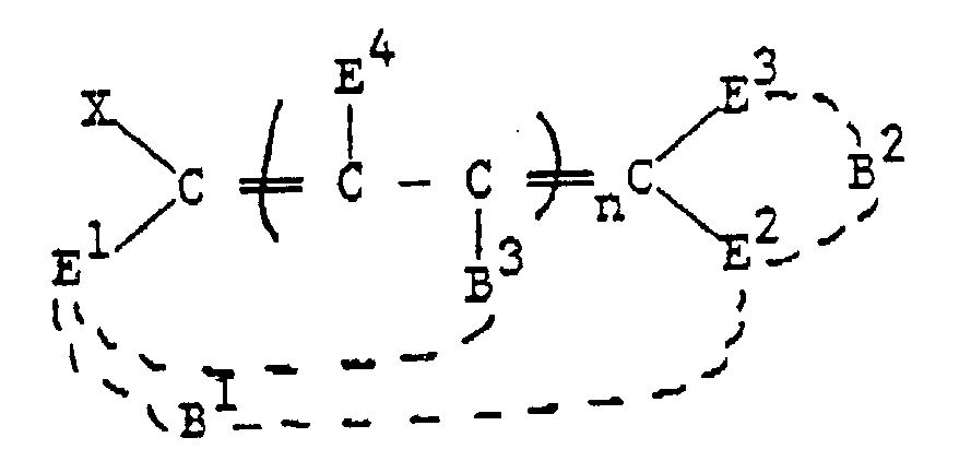
X est un halogène, un alkylsulfonyloxy substitué ou non, un arylsulfonyloxy substitué ou non, ou un acyloxy substitué ou non ;
E¹, E², E³ et E⁴ sont chacun séparément l'hydrogène, un alkyle ou alcényle substitué ou non ayant jusqu'à 6 atomes de carbone, un aryle substitué ou non ayant jusqu'à 10 atomes de carbone, halogène, cyano, benzoxazolyle, nitro, -CO₂R, -COR, -CONH₂, -CONHR, -CONRR, ou -SO₂R, où chaque R est séparément un alkyle ou un alcényle substitué ou non ayant jusqu'à 6 atomes de carbone, ou un aryle substitué ou non ayant jusqu'à 10 atomes de carbone, avec la condition qu'au moins deux des groupes E soient autres que l'hydrogène, alkyle, alcényle, aryle ou halogène ;
B¹ et B² représentent les atomes nécessaires pour compléter d'éventuels cycles à 5 ou 6 chaînons formés avec les groupes carbonyles de E¹, E² ou E³ ;
B³ représente l'hydrogène ou les atomes nécessaires pour compléter un éventuel cycle à 5 ou 6 chaînons formé avec un groupe carbonyle de E¹ ;
et n est 0 ou 1. - Elément selon la revendication 1 caractérisé en ce que n et 0 et E¹ et E² ensemble forment -C(O)NR¹C(O)- où R¹ est l'hydrogène, un alkyle ou alcényle substitué ou non ayant jusqu'à 6 atomes de carbone ou un aryle ayant jusqu'à 10 atomes de carbone.
- Elément selon la revendication 2 caractérisé en ce que l'électrophile est :


- Elément selon la revendication 1 caractérisé en ce que le support porte des séquences répétitives de zones comprenant plusieurs électrophiles distincts, chaque électrophile étant capable de réagir avec un composé coupleur pour former des colorants de différentes teintes.
- Elément selon la revendication 1 caractérisé en ce que le support porte l'électrophile dans une première zone, et l'élément de plus comprend une seconde zone de ce support adjacente et distincte portant le composé coupleur.
- Elément selon la revendication 1 caractérisé en ce que le coupleur est une amine aromatique, un composé hydroxyle aromatique, un composé comprenant un hétérocycle insaturé à 5 chaînons ayant au moins un atome d'azote, d'oxygène ou de soufre, ou un composé de formule G¹-CH₂-G² où G¹ et G² sont chacun séparément :
cyano, aryle substitué ou non, hétérocycle insaturé à 5 ou 6 chaînons contenant N, O, ou S,
-CO₂R², -COR², ou -CONR²R³,
où R² et R³ sont chacun séparément l'hydrogène ou un alkyle, alcényle ou aryle substitué ou non ayant jusqu'à 10 atomes de carbone,
et où G¹ et G² peuvent éventuellement être joints pour former un cycle carboné. - Assemblage pour enregistrer une image de colorant comprenant :(a) un premier élément comprenant un premier support portant sur une de ses faces un composé coupleur capable de réagir avec un électrophile pour former un colorant arylidène, et(b) un second élément comprenant un second support portant sur une de ses faces l'électrophile, caractérisé en ce que l'électrophile a la structure :où

X est un halogène, un alkylsulfonyloxy substitué ou non, un arylsulfonyloxy substitué ou non, ou un acyloxy substitué ou non ;
E¹, E², E³ et E⁴ sont chacun séparément l'hydrogène, un alkyle ou alcényle substitué ou non ayant jusqu'à 6 atomes de carbone, un aryle substitué ou non ayant jusqu'à 10 atomes de carbone, halogène, cyano, benzoxazolyle, nitro, -CO₂R, -COR, -CONH₂, -CONHR, -CONRR, ou -SO₂R, où chaque R est séparément un alkyle ou un alcényle substitué ou non ayant jusqu'à 6 atomes de carbone, ou un aryle substitué ou non ayant jusqu'à 10 atomes de carbone, avec la condition qu'au moins deux des groupes E soient autres que l'hydrogène, alkyle, alcényle, aryle ou halogène ;
B¹ et B² représentent les atomes nécessaires pour compléter d'éventuels cycles à 5 ou 6 chaînons formés avec les groupes carbonyles de E¹, E² ou E³ ;
B³ représente l'hydrogène ou les atomes nécessaires pour compléter un éventuel cycle à 5 ou 6 chaînons formé avec un groupe carbonyle de E¹ ;
et n est 0 ou 1,
où le premier et le second éléments sont superposés de sorte que la face du premier support portant le composé coupleur soit en face de la face du second support portant l'électrophile. - Assemblage selon la revendication 7 caractérisé en ce que le coupleur est une amine aromatique, un composé hydroxyle aromatique, un composé comprenant un hétérocycle insaturé à 5 chaînons ayant au moins un atome d'azote, d'oxygène ou de soufre, ou un composé de formule G¹-CH₂-G² où G¹ et G² sont chacun séparément :
cyano, aryle substitué ou non, hétérocycle insaturé à 5 ou 6 chaînons contenant N, O, ou S,
-CO₂R², -COR², ou -CONR²R³,
où R² et R³ sont chacun séparément l'hydrogène ou un alkyle, alcényle ou aryle substitué ou non ayant jusqu'à 10 atomes de carbone,
et où G¹ et G² peuvent éventuellement être joints pour former un cycle carboné. - Procédé pour former une image de colorant dans lequel on transfère conformément à l'image un électrophile d'un élément donneur comprenant un support portant l'électrophile sur un élément récepteur comprenant un support portant un composé coupleur capable de réagir avec l'électrophile pour former un colorant arylidène et on fait réagir l'électrophile avec le composé coupleur pour former l'image de colorant, caractérisé en ce que l'électrophile a la structure :

E¹, E², E³ et E⁴ sont chacun séparément l'hydrogène, un alkyle ou alcényle substitué ou non ayant jusqu'à 6 atomes de carbone, un aryle substitué ou non ayant jusqu'à 10 atomes de carbone, halogène, cyano, benzoxazolyle, nitro, -CO₂R, -COR, -CONH₂, -CONHR, -CONRR, ou -SO₂R, où chaque R est séparément un alkyle ou un alcényle substitué ou non ayant jusqu'à 6 atomes de carbone, ou un aryle substitué ou non ayant jusqu'à 10 atomes de carbone, avec la condition qu'au moins deux des groupes E soient autres que l'hydrogène, alkyle, alcényle, aryle ou halogène ;
B¹ et B² représentent les atomes nécessaires pour compléter d'éventuels cycles à 5 ou 6 chaînons formés avec les groupes carbonyles de E¹, E² ou E³ ;
B³ représente l'hydrogène ou les atomes nécessaires pour compléter un éventuel cycle à 5 ou 6 chaînons formé avec un groupe carbonyle de E¹ ;
et n est 0 ou 1. - Procédé pour former une image de colorant dans lequel on transfère conformément à l'image un composé coupleur d'un élément donneur comprenant un support portant le composé coupleur sur un élément récepteur comprenant un support portant un électrophile capable de réagir avec le composé coupleur pour former un colorant arylidène et on fait réagir l'électrophile avec le composé coupleur pour former l'image de colorant caractérisé en ce que l'électrophile a la structure :

E¹, E², E³ et E⁴ sont chacun séparément l'hydrogène, un alkyle ou alcényle substitué ou non ayant jusqu'à 6 atomes de carbone, un aryle substitué ou non ayant jusqu'à 10 atomes de carbone, halogène, cyano, benzoxazolyle, nitro, -CO₂R, -COR, -CONH₂, -CONHR, -CONRR, ou -SO₂R, où chaque R est séparément un alkyle ou un alcényle substitué ou non ayant jusqu'à 6 atomes de carbone, ou un aryle substitué ou non ayant jusqu'à 10 atomes de carbone, avec la condition qu'au moins deux des groupes E soient autres que l'hydrogène, alkyle, alcényle, aryle ou halogène ;
B¹ et B² représentent les atomes nécessaires pour compléter d'éventuels cycles à 5 ou 6 chaînons formés avec les groupes carbonyles de E¹, E² ou E³ ;
B³ représente l'hydrogène ou les atomes nécessaires pour compléter un éventuel cycle à 5 ou 6 chaînons formé avec un groupe carbonyle de E¹ ; et n est 0 ou 1.
Applications Claiming Priority (2)
| Application Number | Priority Date | Filing Date | Title |
|---|---|---|---|
| US07/490,116 US5011811A (en) | 1990-03-07 | 1990-03-07 | In situ dye generation for thermal transfer printing |
| US490116 | 1990-03-07 |
Publications (2)
| Publication Number | Publication Date |
|---|---|
| EP0445761A1 EP0445761A1 (fr) | 1991-09-11 |
| EP0445761B1 true EP0445761B1 (fr) | 1994-06-15 |
Family
ID=23946694
Family Applications (1)
| Application Number | Title | Priority Date | Filing Date |
|---|---|---|---|
| EP91103388A Expired - Lifetime EP0445761B1 (fr) | 1990-03-07 | 1991-03-06 | Génération de colorant in situ pour l'impression thermique par transfert de colorant |
Country Status (5)
| Country | Link |
|---|---|
| US (1) | US5011811A (fr) |
| EP (1) | EP0445761B1 (fr) |
| JP (1) | JPH0615268B2 (fr) |
| CA (1) | CA2035760A1 (fr) |
| DE (1) | DE69102453T2 (fr) |
Families Citing this family (8)
| Publication number | Priority date | Publication date | Assignee | Title |
|---|---|---|---|---|
| US5194571A (en) * | 1991-08-19 | 1993-03-16 | Eastman Kodak Company | Colored polyester compositions |
| US5283165A (en) * | 1992-12-23 | 1994-02-01 | Eastman Kodak Company | Pyrrolinone dyes |
| US5424268A (en) * | 1994-05-13 | 1995-06-13 | Polaroid Corporation | Imaging medium and process |
| US5683956A (en) * | 1995-08-30 | 1997-11-04 | Eastman Kodak Company | Thermal dye transfer system with receiver containing amino groups |
| US6334676B1 (en) * | 1997-09-29 | 2002-01-01 | Eastman Kodak Company | Using colorant precursors and reactants in microfluidic printing |
| US6097406A (en) * | 1998-05-26 | 2000-08-01 | Eastman Kodak Company | Apparatus for mixing and ejecting mixed colorant drops |
| US6109746A (en) * | 1998-05-26 | 2000-08-29 | Eastman Kodak Company | Delivering mixed inks to an intermediate transfer roller |
| US7307173B1 (en) | 2004-02-19 | 2007-12-11 | University Of Washington | Pyrroline chromophores |
Family Cites Families (19)
| Publication number | Priority date | Publication date | Assignee | Title |
|---|---|---|---|---|
| US28956A (en) * | 1860-07-03 | Mode of polishing varnish | ||
| US3013013A (en) * | 1959-04-24 | 1961-12-12 | Du Pont | 5-cyanomethylene-2-oxo-3-pyrrolines |
| USRE28956E (en) | 1959-09-28 | 1976-09-07 | Horizons Research Incorporated | Latent image photographic system |
| US3332557A (en) * | 1964-05-26 | 1967-07-25 | Pall Corp | Wire mesh filter element with anchoring rim |
| JPS5243566B2 (fr) * | 1972-08-03 | 1977-10-31 | ||
| JPS5677189A (en) * | 1979-11-30 | 1981-06-25 | Fuji Photo Film Co Ltd | Recording material |
| JPS5769091A (en) * | 1980-10-17 | 1982-04-27 | Ricoh Co Ltd | Peel-off type heatsensitive recording paper |
| US4500896A (en) * | 1983-01-25 | 1985-02-19 | Ricoh Company, Ltd. | Heat-sensitive recording medium affording patterns with different colors |
| JPS60101078A (ja) * | 1983-11-09 | 1985-06-05 | Ricoh Co Ltd | 画像記録方法 |
| JPS60156760A (ja) * | 1984-01-26 | 1985-08-16 | Sumitomo Chem Co Ltd | 複素環状化合物およびそれを用いる染色または着色法 |
| JPS60158262A (ja) * | 1984-01-27 | 1985-08-19 | Sumitomo Chem Co Ltd | 複素環状化合物およびそれを用いる染色または着色法 |
| JPS60161190A (ja) * | 1984-02-01 | 1985-08-22 | Ricoh Co Ltd | 多色画像記録方法 |
| US4614521A (en) * | 1984-06-06 | 1986-09-30 | Mitsubishi Chemical Industries Limited | Transfer recording method using reactive sublimable dyes |
| JPS6131293A (ja) * | 1984-07-24 | 1986-02-13 | Sharp Corp | 感熱記録方法 |
| DE3601525A1 (de) * | 1985-01-21 | 1986-07-24 | Mitsubishi Paper Mills, Ltd., Tokio/Tokyo | Waermeempfindliches und waermeuebertragbares aufzeichnungsblatt |
| JPS61173987A (ja) * | 1985-01-30 | 1986-08-05 | Sugai Kagaku Kogyo Kk | 熱転写記録体 |
| US4745046A (en) * | 1985-06-03 | 1988-05-17 | Polaroid Corporation | Thermal imaging method |
| JPH0649835B2 (ja) * | 1986-03-24 | 1994-06-29 | 日本化薬株式会社 | ピロ−ル系化合物,その製造法並びにそれを使用する染色又は着色法 |
| JPH0639573B2 (ja) * | 1986-07-07 | 1994-05-25 | 日本化薬株式会社 | ピロ−ル系化合物並びにそれを用いる染色又は着色法 |
-
1990
- 1990-03-07 US US07/490,116 patent/US5011811A/en not_active Expired - Lifetime
-
1991
- 1991-02-06 CA CA002035760A patent/CA2035760A1/fr not_active Abandoned
- 1991-03-06 EP EP91103388A patent/EP0445761B1/fr not_active Expired - Lifetime
- 1991-03-06 DE DE69102453T patent/DE69102453T2/de not_active Expired - Fee Related
- 1991-03-07 JP JP3041675A patent/JPH0615268B2/ja not_active Expired - Lifetime
Also Published As
| Publication number | Publication date |
|---|---|
| DE69102453D1 (de) | 1994-07-21 |
| CA2035760A1 (fr) | 1991-09-08 |
| DE69102453T2 (de) | 1995-01-26 |
| EP0445761A1 (fr) | 1991-09-11 |
| US5011811A (en) | 1991-04-30 |
| JPH04219288A (ja) | 1992-08-10 |
| JPH0615268B2 (ja) | 1994-03-02 |
Similar Documents
| Publication | Publication Date | Title |
|---|---|---|
| US4695287A (en) | Cyan dye-donor element used in thermal dye transfer | |
| US4866029A (en) | Arylidene pyrazolone dye-donor element for thermal dye transfer | |
| US4695286A (en) | High molecular weight polycarbonate receiving layer used in thermal dye transfer | |
| US4740497A (en) | Polymeric mixture for dye-receiving element used in thermal dye transfer | |
| US4866025A (en) | Thermally-transferable fluorescent diphenylpyrazolines | |
| EP0356981B1 (fr) | 7-Aminocoumarines fluorescentes transférables par la chaleur | |
| US4891352A (en) | Thermally-transferable fluorescent 7-aminocarbostyrils | |
| US5523274A (en) | Thermal dye transfer system with low-Tg polymeric receiver containing an acid moiety | |
| US4891351A (en) | Thermally-transferable fluorescent compounds | |
| US4871715A (en) | Phthalate esters in receiving layer for improved dye density transfer | |
| US4839336A (en) | Alpha-cyano arylidene pyrazolone magenta dye-donor element for thermal dye transfer | |
| US4871714A (en) | Thermally-transferable fluorescent diphenyl ethylenes | |
| EP0356982B1 (fr) | Oxazoles fluorescents transférables par la chaleur | |
| US4748149A (en) | Thermal print element comprising a yellow merocyanine dye stabilized with a cyan indoaniline dye | |
| US4866027A (en) | Thermally-transferable polycyclic-aromatic fluorescent materials | |
| EP0234043A2 (fr) | Couche de lubrification pour un élément donneur de colorant utilisé pour le transfert de colorant par la chaleur | |
| US4725574A (en) | Thermal print element comprising a yellow merocyanine dye stabilized with a cyan indoaniline dye | |
| EP0514900B1 (fr) | Composés organiques/minéraux pour des couches adhésives pour un élément donneur de colorant pour le transfert thermique | |
| US4876236A (en) | Material for increasing dye transfer efficiency in dye-donor elements used in thermal dye transfer | |
| US5011811A (en) | In situ dye generation for thermal transfer printing | |
| US5350732A (en) | Subbing layer for dye-donor element used in thermal dye transfer | |
| US4933226A (en) | Thermal print element comprising a magenta 3-aryl-2-arylazo-5-aminothiazole or aminothiophene dye stabilized with a cyan indoaniline dye | |
| US4853366A (en) | Pyrazolidinedione arylidene dye-donor element for thermal dye transfer | |
| US5166129A (en) | Benzomorpholinepyrroline dye-donor element for thermal dye transfer | |
| US4876238A (en) | Increasing dye transfer efficient in dye-donor elements used in thermal dye transfer |
Legal Events
| Date | Code | Title | Description |
|---|---|---|---|
| PUAI | Public reference made under article 153(3) epc to a published international application that has entered the european phase |
Free format text: ORIGINAL CODE: 0009012 |
|
| 17P | Request for examination filed |
Effective date: 19910620 |
|
| AK | Designated contracting states |
Kind code of ref document: A1 Designated state(s): AT BE CH DE DK ES FR GB GR IT LI LU NL SE |
|
| 17Q | First examination report despatched |
Effective date: 19930908 |
|
| RBV | Designated contracting states (corrected) |
Designated state(s): BE DE FR GB NL |
|
| GRAA | (expected) grant |
Free format text: ORIGINAL CODE: 0009210 |
|
| AK | Designated contracting states |
Kind code of ref document: B1 Designated state(s): BE DE FR GB NL |
|
| REF | Corresponds to: |
Ref document number: 69102453 Country of ref document: DE Date of ref document: 19940721 |
|
| ET | Fr: translation filed | ||
| PLBE | No opposition filed within time limit |
Free format text: ORIGINAL CODE: 0009261 |
|
| STAA | Information on the status of an ep patent application or granted ep patent |
Free format text: STATUS: NO OPPOSITION FILED WITHIN TIME LIMIT |
|
| 26N | No opposition filed | ||
| PGFP | Annual fee paid to national office [announced via postgrant information from national office to epo] |
Ref country code: NL Payment date: 19951231 Year of fee payment: 6 |
|
| PGFP | Annual fee paid to national office [announced via postgrant information from national office to epo] |
Ref country code: FR Payment date: 19960307 Year of fee payment: 6 |
|
| PGFP | Annual fee paid to national office [announced via postgrant information from national office to epo] |
Ref country code: BE Payment date: 19960409 Year of fee payment: 6 |
|
| PG25 | Lapsed in a contracting state [announced via postgrant information from national office to epo] |
Ref country code: BE Effective date: 19970331 |
|
| BERE | Be: lapsed |
Owner name: EASTMAN KODAK CY Effective date: 19970331 |
|
| PG25 | Lapsed in a contracting state [announced via postgrant information from national office to epo] |
Ref country code: NL Effective date: 19971001 |
|
| PG25 | Lapsed in a contracting state [announced via postgrant information from national office to epo] |
Ref country code: FR Free format text: LAPSE BECAUSE OF NON-PAYMENT OF DUE FEES Effective date: 19971128 |
|
| NLV4 | Nl: lapsed or anulled due to non-payment of the annual fee |
Effective date: 19971001 |
|
| REG | Reference to a national code |
Ref country code: FR Ref legal event code: ST |
|
| PGFP | Annual fee paid to national office [announced via postgrant information from national office to epo] |
Ref country code: DE Payment date: 19991229 Year of fee payment: 10 |
|
| PGFP | Annual fee paid to national office [announced via postgrant information from national office to epo] |
Ref country code: GB Payment date: 20000204 Year of fee payment: 10 |
|
| PG25 | Lapsed in a contracting state [announced via postgrant information from national office to epo] |
Ref country code: GB Free format text: LAPSE BECAUSE OF NON-PAYMENT OF DUE FEES Effective date: 20010306 |
|
| GBPC | Gb: european patent ceased through non-payment of renewal fee |
Effective date: 20010306 |
|
| PG25 | Lapsed in a contracting state [announced via postgrant information from national office to epo] |
Ref country code: DE Free format text: LAPSE BECAUSE OF NON-PAYMENT OF DUE FEES Effective date: 20020101 |