EP0446833B1 - Dispositif de commande d'affichage permettant l'affichage clair, de la performance de fonctionnement d'un processeur arithmétique - Google Patents
Dispositif de commande d'affichage permettant l'affichage clair, de la performance de fonctionnement d'un processeur arithmétique Download PDFInfo
- Publication number
- EP0446833B1 EP0446833B1 EP91103683A EP91103683A EP0446833B1 EP 0446833 B1 EP0446833 B1 EP 0446833B1 EP 91103683 A EP91103683 A EP 91103683A EP 91103683 A EP91103683 A EP 91103683A EP 0446833 B1 EP0446833 B1 EP 0446833B1
- Authority
- EP
- European Patent Office
- Prior art keywords
- signal
- count
- producing
- counting
- peak
- Prior art date
- Legal status (The legal status is an assumption and is not a legal conclusion. Google has not performed a legal analysis and makes no representation as to the accuracy of the status listed.)
- Expired - Lifetime
Links
Images
Classifications
-
- G—PHYSICS
- G06—COMPUTING OR CALCULATING; COUNTING
- G06F—ELECTRIC DIGITAL DATA PROCESSING
- G06F11/00—Error detection; Error correction; Monitoring
- G06F11/30—Monitoring
- G06F11/32—Monitoring with visual or acoustical indication of the functioning of the machine
- G06F11/324—Display of status information
- G06F11/328—Computer systems status display
-
- G—PHYSICS
- G06—COMPUTING OR CALCULATING; COUNTING
- G06F—ELECTRIC DIGITAL DATA PROCESSING
- G06F11/00—Error detection; Error correction; Monitoring
- G06F11/30—Monitoring
- G06F11/34—Recording or statistical evaluation of computer activity, e.g. of down time, of input/output operation ; Recording or statistical evaluation of user activity, e.g. usability assessment
Definitions
- This invention relates to an apparatus for controlling a display unit which is for displaying the operation performance of an arithmetic processor, such as a supercomputer.
- the arithmetic processor has an operation performance which is generally evaluated by an operation number of operation of the arithmetic processor during a predetermined time interval.
- a display unit is used for displaying the operation number under control by a display control apparatus.
- a conventional display control apparatus includes a determining, a counting, a processing, and a sending circuit.
- the determining circuit is for determining a plurality of consecutive time intervals.
- the counting circuit is for counting the operation number during each of the consecutive time intervals to produce a count signal representative of the operation number.
- the processing circuit processes the count signal into a performance signal representative of the operation performance.
- the display unit visibly expresses the operation number in each of the time intervals. In this event, it is important for evaluation of the operation performance to discriminate the operation number that is relatively great and that will be called a peak operation number.
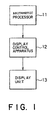
- the system comprises an arithmetic processor 11, a display control apparatus 12 according to an embodiment of the present invention, and a display unit 13.
- the arithmetic processor 11 is, for example, a supercomputer. Whenever an operation comes to an end, the arithmetic processor 11 produces an end signal in the manner known in the art. The end signal is representative of the end of the operation and is supplied to the display control apparatus 12. Supplied with the end signal, the display control apparatus 12 produces a performance signal representative of the operation performance of the arithmetic processor 11. The performance signal is sent to the display unit 13. Responsive to the performance signal, the display unit 13 visually display a picture or display related to the operation performance.
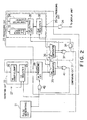
- the display control apparatus 12 comprises pulse generating, counting, processing, and sending circuits 21, 22, 23, and 24 which will be described as the description proceeds.
- the pulse generating circuit 21 is for generating first and second pulse signals.
- the first pulse signal is intermittently generated at a first predetermined period (T) of, for example, 4ms and is supplied to the processing circuit 23.
- the second pulse signal is intermittently generated at a second predetermined period (t) which is shorter than the first predetermined period and which is of, for example, 128 ⁇ s.
- the second pulse signal is supplied to the counting and the processing circuits 22 and 23.
- the pulse generating circuit 21 is referred to as a determining arrangement for determining a plurality of consecutive time intervals. Each time interval may be equal to the second predetermined period.
- the counting circuit 22 is for counting an operation number of operations of the arithmetic processor 11 during each of the time intervals and comprises a first register 25 and a first adder element 26.
- the first register 25 is connected to the pulse generating circuit 21 and an apparatus input terminal 27 which is connected to the arithmetic processor 11.
- the first adder element 26 is connected to the first register 25 and is operable in the manner which will presently be described.
- the first register 25 is for memorizing a first number and is supplied with the end signal through the apparatus input terminal 27 from the arithmetic processor 11. Whenever the end signal is supplied to the first register 25, the first adder element 26 adds a predetermined decimal number, for example, one to the first number into a counting circuit sum. The first number is cleared in the first register 25 whenever the second pulse signal is intermittently generated. As a result, the first register 25 produces a count signal representative of the operation number.
- the processing circuit 23 is supplied with the count signal and comprises first producing, second producing, and comparing circuits 28, 29, and 31 which will be described in the following.
- the first producing circuit 28 is connected to the first register 25 and is for producing a peak signal representative of a peak number of the operation number represented by the count signal. The peak number is renewed in the manner which will later become clear. The peak number is kept in the first producing circuit 28. It is preferable that the first producing circuit 28 is a register known in the art.
- the second producing circuit 29 is for producing the above-mentioned performance signal and comprises a second register 32, a second adder element 33, a subtractor element 34, and a selecting circuit 35.
- the second register 32 is connected to the comparing and the selecting circuits 31 and 35.
- the second adder and the subtractor elements 33 and 34 are supplied from the second register 32 with a second number which is memorized in the second register 32.
- the selecting circuit 35 is connected to the comparing circuit 31, the second adder element 33, and the subtractor element 34.
- the second register 32 is supplied from the comparing circuit 31 with a local signal which will later become clear.
- the second adder element 33 is for counting up, whenever the local signal is supplied to the second register 32, a first count representative of how many times the local signal is produced.
- the second adder element 33 produces a count up signal representative of the first count.
- the subtractor element 34 is for counting down, whenever the local signal is supplied to the second register 32, a second count representative of how many times the local signal is produced.
- the subtractor 34 produces a count down signal representative of the second count.
- the selecting circuit 35 is for selecting one of the second adder and the subtractor elements 33 and 34 in compliance with an internal signal produced by the comparing circuit 31 in the manner which will later be described.
- the internal signal is represented by one of logic "0" and "1" levels.
- the selecting circuit 35 connects the second adder element 33 to the second register 32.
- a predetermined decimal number for example, one is added to the second number whenever the local signal is supplied to the second register 32.
- the selecting circuit 35 connects the subtractor element 34 to the second register 32.
- the subtractor element 34 When the subtractor element 34 is selected, the predetermined decimal number is subtracted from the second number whenever the local signal is supplied to the second register 32.
- the second register 32 produces the performance signal that is representative of the second number.
- the second register 32 will be referred to as an internal producing arrangement.
- the second adder element 33 will be called a counting up arrangement.
- the subtractor element 34 will be named a counting down arrangement.
- the performance signal is sent to the display unit 13 through the sending circuit 24.
- the sending circuit 24 is a buffer gate known in the art.
- the comparing circuit 31 is for carrying out comparison between the peak signal and the performance signal to produce, as the local signal, a first result signal representative of a result of the comparison.
- the comparing circuit 31 comprises a first comparator 36, a first OR element 37, and a first AND element 38.
- the first comparator 36 is connected to the first producing circuit 28 and the second register 32 and has a first, a second, and a third output terminal.
- the first output terminal is connected to the selecting circuit 35.
- the first OR element 37 is connected to the first and the second output terminals of the first comparator 36.
- the third output terminal is used in the manner which will presently be described.
- the first AND element 38 is connected to the first OR element 37, the pulse generating circuit 21, and the second register 32.
- the first comparator 36 is for carrying out a comparison between the peak and the performance signals to produce the internal signal. Namely, the first comparator 36 will be referred to as an internal comparing arrangement. When the peak number is less than the second number, the internal signal is sent to the first output terminal with a logic "1" level. Otherwise, the internal signal is given a logic "0" level at the first output terminal. In both events, the internal signal is supplied to the selecting circuit 35 and the first OR element 37 through the first output terminal.
- the internal signal When the peak number is greater than the second number, the internal signal is sent to the second output terminal with the logic “1" level and is supplied to the first OR element 37. Otherwise, the internal signal has the logic "0" level at the second output terminal.
- the first OR element 37 When the internal signal has the logic "1" level either at one of or at both of the first and the second output terminals, the first OR element 37 produces a first OR signal having a logic "1” level. Otherwise, the first OR signal is given a logic "0" level.
- the first AND element 38 produces the first result signal of a logic "1" level in response to the first pulse signal. Otherwise, the first result signal is given a logic "0" level even if the first pulse signal is intermittently supplied to the first AND element 38. Responsive to the first result signal, the second register 32 renews the second number to zero.
- a combination of the first OR and the first AND elements 37 and 38 will be referred to as an internal processing arrangement.
- the internal signal is sent to the third output terminal with the logic "1" level. Otherwise, the internal signal is given the logic "0" level at the third output terminal.
- the processing circuit 23 further comprises a second comparator 39, a second OR element 41, and a second AND element 42.
- the second comparator 39 is connected to the first register 25 and the first producing circuit 28.
- the second OR element 41 is connected to the second comparator 39 and the third output terminal of the first comparator 36.
- the second AND element 42 is connected to the second OR element 41, the pulse generating circuit 21, and the first producing circuit 28.
- the second comparator 39 is for carrying out comparison between the count and the peak signals to produce a second result signal representative of a result of the comparison.
- the second result signal represents one of logic "0" and "1" levels. When the first number is greater than the peak number, the second result signal is given the logic "1" level. Otherwise, the second result signal has the logic "0" level.
- the second OR element 41 When the logic "1" level is given to at least one of the second result signal and the internal signal that is supplied to the second OR element 41, the second OR element 41 produces a second OR signal having the logic "1" level. Otherwise, the second OR signal has the logic "0" level.
- the second AND element 42 When the second OR signal has the logic "1" level, the second AND element 42 produces a control signal of a logic "1" level when supplied with the second pulse signal. Otherwise, the control signal has the logic "0" level even if the second pulse signal is intermittently supplied to the second AND element 42. Responsive to the control signal, the first producing circuit 28 resets the peak number to zero.
- a combination of the second OR and the second AND elements 41 and 42 will be referred to as a control arrangement.
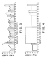
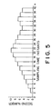
- the consecutive time intervals are defined by a succession of sampling time instants which are depicted in each of Figs. 3 through 5 and are indicated by consecutive integers. It will be assumed merely for convenience of the description that the first predetermined period is twice as long as the second predetermined period. It may be mentioned here that the sampling time instants are spaced apart in Fig. 5 by the first predetermined period.
- the first number changes as exemplified in Fig. 3.
- the first number is memorized in the first register 25. It is to be noted that the first number has a higher value during a particular time interval defined between adjacent ones (6) and (7) of the sampling time instants. Such a time interval will be referred to in the following as the time instant (6). In the example, the higher value is equal to ten.
- the peak number is memorized in the first producing circuit 28.
- the peak number is compared with the first number in the second comparator 39.
- the peak number is less than the first number, the latter number is used as the peak number. Otherwise, the peak number is held constant.
- the peak number is equal to four at the sampling time instants (1) through (5). This is because the first number is equal to four at the sampling time instant (0) and is less than four at the sampling time instants (1) through (4).
- the peak number is renewed to five at the sampling time instant (6) because the first number is equal to five at the sampling time instant (5).
- the peak number becomes equal to ten at the sampling time instant (7) because the first number is ten at the sampling time instant (6).
- the peak number is held equal to ten at the sampling time instants (7) through (20). This is because the first number is not greater than ten at the sampling time instants (7) through (19).
- the peak number is cleared at the sampling time instant (21).
- the second number is memorized in the second register 32.
- the second number is compared with the peak number in the first comparator 36.
- the predetermined decimal number is added to the second number.
- the second number increases to the peak number. For example, one is added to the second number at each of even-numbered ones of the sampling time instants (2) through (20). This is because the second number is less than the peak number at the sampling time instants (1) through (19).
- the peak number is cleared when the second number becomes equal to the peak number.
- the first number is used as the peak number.
- the peak number is cleared at the sampling time instant (21) because the second number is equal to ten at the sampling time instant (20).
- the peak number becomes equal to five because the first number is five at the sampling time instant (20).
- the peak number is held equal to five at the sampling time instants (21) through (30). This is because the first number is not greater than five at the sampling time instants (21) through (29).
- the second number is compared with the peak number in the first comparator 36.
- the predetermined decimal number is subtracted from the second number.
- the second number decreases towards the peak number. For example, one is subtracted from the second number at each of even-numbered ones of the sampling time instants (22) through (30). This is because the second number is greater than the peak number at the sampling time instants (22) through (30).
- the peak number is cleared when the second number becomes equal to the peak number.
- the first number is used as the peak number.
- the peak number is cleared at the sampling time instant (31) because the second number becomes equal to the peak number at the sampling time instant (30).
- the peak number becomes equal to six because the first number is six at the sampling time instant (30).
Landscapes
- Engineering & Computer Science (AREA)
- General Engineering & Computer Science (AREA)
- Theoretical Computer Science (AREA)
- Computer Hardware Design (AREA)
- Computing Systems (AREA)
- Quality & Reliability (AREA)
- Physics & Mathematics (AREA)
- General Physics & Mathematics (AREA)
- Measurement Of Current Or Voltage (AREA)
- Debugging And Monitoring (AREA)
- Control Of Indicators Other Than Cathode Ray Tubes (AREA)
Claims (5)
- Appareil de commande d'affichage pour la commande d'une unité d'affichage pour afficher une performance opérationnelle d'un processeur arithmétique produisant un signal approprié chaque fois que ledit processeur arithmétique fonctionne, ledit appareil de commande d'affichage englobant:a) un moyen de détermination (21) pour déterminer plusieurs premiers intervalles de temps consécutifs;b) un moyen de comptage (22) sensible audit signal approprié pour compter un nombre d'opérations dudit processeur arithmétique au cours de chacun desdits premiers intervalles de temps pour produire un signal numérique représentatif dudit nombre d'opérations; etc) un moyen de traitement (23) pour traiter ledit signal numérique en fonction desdits premiers intervalles de temps pour produire un signal traité qui est représentatif de ladite performance opérationnelle et qui est acheminé à ladite unité d'affichage,caractérisé en ce que ledit moyen de traitement (23) comprend:c1) un premier moyen de production (28) relié audit moyen de comptage pour produire un signal maximal correspondant audit signal numérique, ledit signal maximal étant remplacé par ledit signal numérique uniquement lorsque ledit signal maximal est inférieur audit signal numérique au cours de chacun desdits premiers intervalles de temps;c2) un moyen de comparaison (31) relié audit premier moyen de production (28) pour comparer ledit signal maximal à un signal de comparaison pour produire un signal de sélection;c3) un second moyen de production (29) relié audit moyen de comparaison (31) pour produire ledit signal traité, dans lequel, en réponse audit signal de sélection,- un premier nombre est ajouté audit signal traité après chaque second intervalle de temps si ledit signal traité est inférieur au signal maximal;- un second nombre est soustrait de chaque signal traité après chaque second intervalle de temps si ledit signal traité est supérieur au signal maximal;- et le nombre maximal est remplacé par le signal numérique si ledit signal traité devient égal au nombre maximal; etc4) un moyen d'alimentation relié audit moyen de comparaison et audit second moyen de production pour acheminer, à titre dudit signal de comparaison, ledit signal traité audit moyen de comparaison.
- Appareil de commande d'affichage selon la revendication 1, dans lequel ledit processeur arithmétique est utilisé pour produire un signal de fin représentatif de la fin de ladite opération, ledit moyen de comptage étant relié audit processeur arithmétique pour compter , à titre dudit nombre d'opérations, un nombre correspondant audit signal terminal au cours de chacun desdits intervalles de temps pour produire ledit signal numérique.
- Appareil de commande d'affichage selon la revendication 1 ou 2, dans lequel ledit moyen de détermination (21) comprend un premier moyen de génération pour générer par intermittence un premier signal d'impulsion à un premier intervalle de temps prédéterminé qui est égal à plusieurs desdits premiers intervalles de temps consécutifs, ledit moyen de comparaison (31) comprenant:un moyen de comparaison interne (36) relié audit premier moyen de production (28) et audit second moyen de production (29) pour établir une comparaison entre ledit signal maximal et ledit signal traité pour produire un signal interne; etun moyen de traitement interne relié audit moyen de comparaison interne, audit premier moyen de génération et audit second moyen de production (29) pour traiter ledit signal interne pour obtenir un signal de sélection en correspondance avec ledit premier signal d'impulsion.
- Appareil de commande d'affichage selon la revendication 3, dans lequel ledit moyen de détermination (21) comprend en outre un second moyen de génération pour générer par intermittence un second signal d'impulsion à un second laps de temps prédéterminé qui est plus court que ledit premier laps de temps prédéterminé, ledit moyen de traitement comprenant en outre:un moyen de comparaison supplémentaire relié audit moyen de comptage et audit premier moyen de production pour établir une comparaison supplémentaire entre ledit signal de comptage et ledit signal maximal pour produire un signal de résultat supplémentaire représentatif du résultat de ladite comparaison supplémentaire; etun moyen de commande relié audit moyen de comparaison supplémentaire, audit second moyen de génération, audit moyen de comparaison interne et audit premier moyen de production pour commander la mise en service dudit premier moyen de production en fonction dudit résultat supplémentaire, de ladite première impulsion et dudit signal interne.
- Appareil de commande d'affichage selon la revendication 3 ou 4, dans lequel ledit second moyen de production (29) comprend:un moyen d'addition (33) relié audit moyen de traitement interne pour additionner, chaque fois que ledit signal de sélection est produit, un premier nombre représentatif du nombre de fois que ledit signal de sélection a été produit, ledit moyen d'addition produisant un signal d'addition représentatif du premier nombre;un moyen de soustraction (34) relié audit moyen de traitement interne pour soustraire, chaque fois que ledit signal de sélection est produit, un second nombre représentatif du nombre de fois que ledit signal de sélection est produit, ledit moyen de soustraction produisant un signal de soustraction représentatif dudit second nombre;un moyen de sélection (35) relié audit moyen de comparaison interne (36) pour sélectionner, soit ledit moyen d'addition, soit ledit moyen de soustraction en fonction dudit signal interne, et pour produire, soit ledit signal d'addition, soit ledit signal de soustraction à titre de signal de comptage sélectionné; etun moyen de production interne (32) relié audit moyen de sélection et audit moyen de traitement interne, ainsi qu'à ladite unité d'affichage pour produire ledit signal traité conformément audit signal de comptage sélectionné pour acheminer ledit signal traité à ladite unité d'affichage.
Applications Claiming Priority (2)
| Application Number | Priority Date | Filing Date | Title |
|---|---|---|---|
| JP2060174A JP2682189B2 (ja) | 1990-03-12 | 1990-03-12 | 表示制御回路 |
| JP60174/90 | 1990-03-12 |
Publications (3)
| Publication Number | Publication Date |
|---|---|
| EP0446833A2 EP0446833A2 (fr) | 1991-09-18 |
| EP0446833A3 EP0446833A3 (en) | 1992-10-07 |
| EP0446833B1 true EP0446833B1 (fr) | 1997-07-30 |
Family
ID=13134530
Family Applications (1)
| Application Number | Title | Priority Date | Filing Date |
|---|---|---|---|
| EP91103683A Expired - Lifetime EP0446833B1 (fr) | 1990-03-12 | 1991-03-11 | Dispositif de commande d'affichage permettant l'affichage clair, de la performance de fonctionnement d'un processeur arithmétique |
Country Status (6)
| Country | Link |
|---|---|
| US (1) | US5243321A (fr) |
| EP (1) | EP0446833B1 (fr) |
| JP (1) | JP2682189B2 (fr) |
| AU (1) | AU646022B2 (fr) |
| CA (1) | CA2037977C (fr) |
| DE (1) | DE69127008T2 (fr) |
Families Citing this family (3)
| Publication number | Priority date | Publication date | Assignee | Title |
|---|---|---|---|---|
| US6246306B1 (en) * | 1999-02-04 | 2001-06-12 | Klaus A. Gruner | Electromagnetic relay with pressure spring |
| US6707542B1 (en) * | 2000-01-28 | 2004-03-16 | Reichert, Inc. | Refractometer for monitoring water content in fluids |
| AU2002343525A1 (en) | 2001-10-17 | 2003-04-28 | Lonmore, Lc | Variable flow control devices, related applications, and related methods |
Family Cites Families (11)
| Publication number | Priority date | Publication date | Assignee | Title |
|---|---|---|---|---|
| US3600565A (en) * | 1969-01-02 | 1971-08-17 | Us Navy | Signal tracker and analyzer |
| US3538316A (en) * | 1969-04-21 | 1970-11-03 | Us Navy | Tolerance computer |
| US4199729A (en) * | 1975-03-20 | 1980-04-22 | Compagnie Industrielle des Telecommunications Cit-Aicatel | Variable peak detector |
| US4034353A (en) * | 1975-09-15 | 1977-07-05 | Burroughs Corporation | Computer system performance indicator |
| JPS5621191A (en) * | 1979-07-30 | 1981-02-27 | Nippon Electric Co | Display unit |
| US4509044A (en) * | 1981-05-13 | 1985-04-02 | Nippon Seiki Kabushiki Kaisha | Device which accurately displays changes in a quantity to be measured |
| US4503549A (en) * | 1982-07-16 | 1985-03-05 | The Babcock & Wilcox Company | Interpolating function generator for transmitter square root extraction |
| US4567572A (en) * | 1983-02-22 | 1986-01-28 | The United States Of America As Represented By The Director Of The National Security Agency | Fast parallel sorting processor |
| DE3521610A1 (de) * | 1985-06-15 | 1986-12-18 | Messerschmitt-Bölkow-Blohm GmbH, 8012 Ottobrunn | Geraet zum erkennen relativer extrema |
| JPS63193216A (ja) * | 1987-02-06 | 1988-08-10 | Hitachi Ltd | 階層型救援方式 |
| AU606559B2 (en) * | 1987-12-24 | 1991-02-07 | Nec Corporation | Circuit for comparing a plurality of binary inputs |
-
1990
- 1990-03-12 JP JP2060174A patent/JP2682189B2/ja not_active Expired - Lifetime
-
1991
- 1991-03-11 CA CA002037977A patent/CA2037977C/fr not_active Expired - Fee Related
- 1991-03-11 DE DE69127008T patent/DE69127008T2/de not_active Expired - Fee Related
- 1991-03-11 EP EP91103683A patent/EP0446833B1/fr not_active Expired - Lifetime
- 1991-03-12 AU AU72840/91A patent/AU646022B2/en not_active Ceased
- 1991-03-12 US US07/667,310 patent/US5243321A/en not_active Expired - Fee Related
Also Published As
| Publication number | Publication date |
|---|---|
| CA2037977A1 (fr) | 1991-09-13 |
| DE69127008D1 (de) | 1997-09-04 |
| EP0446833A3 (en) | 1992-10-07 |
| AU7284091A (en) | 1991-09-12 |
| CA2037977C (fr) | 1994-04-05 |
| US5243321A (en) | 1993-09-07 |
| JP2682189B2 (ja) | 1997-11-26 |
| EP0446833A2 (fr) | 1991-09-18 |
| JPH03260848A (ja) | 1991-11-20 |
| AU646022B2 (en) | 1994-02-03 |
| DE69127008T2 (de) | 1997-11-20 |
Similar Documents
| Publication | Publication Date | Title |
|---|---|---|
| KR100243799B1 (ko) | 비디오 신호의 기수/우수 필드 검출기 | |
| EP0404395A3 (fr) | Système pour traitement d'image | |
| US5355397A (en) | Clock start up stabilization for computer systems | |
| EP0534129A1 (fr) | Circuit d'interface pour la transmission de données | |
| EP0446833B1 (fr) | Dispositif de commande d'affichage permettant l'affichage clair, de la performance de fonctionnement d'un processeur arithmétique | |
| KR850008593A (ko) | 동기장치 | |
| KR100232934B1 (ko) | 화상 처리 시스템 | |
| WO1979000585A1 (fr) | Dispositif de mesure du rapport entre un nombre d'evenements consecutifs d'une premiere serie d'evenements et d'une seconde serie d'evenements | |
| US4138693A (en) | Information density decision circuit | |
| JP2625249B2 (ja) | フレーム検出回路 | |
| JP3190800B2 (ja) | 転送速度切り替え機能付き非同期転送回路 | |
| JP2862926B2 (ja) | フレーム同期保護回路 | |
| JPH0730409A (ja) | 急速復帰計数デバイス | |
| JP2897404B2 (ja) | データ伝送装置及び方法 | |
| JP3098503B2 (ja) | 前方後方保護段数の検出方法、その装置および前方後方保護段数の検出方法を記録した記録媒体 | |
| JP2870242B2 (ja) | 競合形同期保護回路 | |
| KR0163537B1 (ko) | 정극성 동기 검출기 | |
| EP0187758A1 (fr) | Appareil de comptage avec des sous-compteurs independants | |
| JPS61182590A (ja) | タイマ−カウンタ方式 | |
| JPS6013591B2 (ja) | 多箇所走査方式 | |
| JPH0575562A (ja) | ポインタ処理装置 | |
| JPH0621937A (ja) | フレーム同期保護回路 | |
| JPS61287314A (ja) | スクランブラ・デスクランブラ回路 | |
| JP2000165371A (ja) | 前方後方保護段数の検出方法、その装置および前方後方保護段数の検出方法を記録した記録媒体 | |
| JPS63164676A (ja) | 画像処理装置 |
Legal Events
| Date | Code | Title | Description |
|---|---|---|---|
| PUAI | Public reference made under article 153(3) epc to a published international application that has entered the european phase |
Free format text: ORIGINAL CODE: 0009012 |
|
| 17P | Request for examination filed |
Effective date: 19910403 |
|
| AK | Designated contracting states |
Kind code of ref document: A2 Designated state(s): BE DE FR GB IT NL |
|
| PUAL | Search report despatched |
Free format text: ORIGINAL CODE: 0009013 |
|
| AK | Designated contracting states |
Kind code of ref document: A3 Designated state(s): BE DE FR GB IT NL |
|
| 17Q | First examination report despatched |
Effective date: 19950622 |
|
| GRAG | Despatch of communication of intention to grant |
Free format text: ORIGINAL CODE: EPIDOS AGRA |
|
| GRAH | Despatch of communication of intention to grant a patent |
Free format text: ORIGINAL CODE: EPIDOS IGRA |
|
| GRAH | Despatch of communication of intention to grant a patent |
Free format text: ORIGINAL CODE: EPIDOS IGRA |
|
| GRAA | (expected) grant |
Free format text: ORIGINAL CODE: 0009210 |
|
| AK | Designated contracting states |
Kind code of ref document: B1 Designated state(s): BE DE FR GB IT NL |
|
| PG25 | Lapsed in a contracting state [announced via postgrant information from national office to epo] |
Ref country code: NL Free format text: LAPSE BECAUSE OF FAILURE TO SUBMIT A TRANSLATION OF THE DESCRIPTION OR TO PAY THE FEE WITHIN THE PRESCRIBED TIME-LIMIT Effective date: 19970730 Ref country code: BE Effective date: 19970730 Ref country code: FR Effective date: 19970730 Ref country code: IT Free format text: LAPSE BECAUSE OF FAILURE TO SUBMIT A TRANSLATION OF THE DESCRIPTION OR TO PAY THE FEE WITHIN THE PRE;WARNING: LAPSES OF ITALIAN PATENTS WITH EFFECTIVE DATE BEFORE 2007 MAY HAVE OCCURRED AT ANY TIME BEFORE 2007. THE CORRECT EFFECTIVE DATE MAY BE DIFFERENT FROM THE ONE RECORDED.SCRIBED TIME-LIMIT Effective date: 19970730 |
|
| REF | Corresponds to: |
Ref document number: 69127008 Country of ref document: DE Date of ref document: 19970904 |
|
| EN | Fr: translation not filed | ||
| NLV1 | Nl: lapsed or annulled due to failure to fulfill the requirements of art. 29p and 29m of the patents act | ||
| PG25 | Lapsed in a contracting state [announced via postgrant information from national office to epo] |
Ref country code: GB Free format text: LAPSE BECAUSE OF NON-PAYMENT OF DUE FEES Effective date: 19980311 |
|
| PLBE | No opposition filed within time limit |
Free format text: ORIGINAL CODE: 0009261 |
|
| STAA | Information on the status of an ep patent application or granted ep patent |
Free format text: STATUS: NO OPPOSITION FILED WITHIN TIME LIMIT |
|
| 26N | No opposition filed | ||
| GBPC | Gb: european patent ceased through non-payment of renewal fee |
Effective date: 19980311 |
|
| PGFP | Annual fee paid to national office [announced via postgrant information from national office to epo] |
Ref country code: DE Payment date: 19990319 Year of fee payment: 9 |
|
| PG25 | Lapsed in a contracting state [announced via postgrant information from national office to epo] |
Ref country code: DE Free format text: LAPSE BECAUSE OF NON-PAYMENT OF DUE FEES Effective date: 20010103 |