EP0447422B1 - Systeme d'elements articules pour des machines de chargement - Google Patents
Systeme d'elements articules pour des machines de chargement Download PDFInfo
- Publication number
- EP0447422B1 EP0447422B1 EP89913264A EP89913264A EP0447422B1 EP 0447422 B1 EP0447422 B1 EP 0447422B1 EP 89913264 A EP89913264 A EP 89913264A EP 89913264 A EP89913264 A EP 89913264A EP 0447422 B1 EP0447422 B1 EP 0447422B1
- Authority
- EP
- European Patent Office
- Prior art keywords
- arm
- lift
- link
- lever
- shift
- Prior art date
- Legal status (The legal status is an assumption and is not a legal conclusion. Google has not performed a legal analysis and makes no representation as to the accuracy of the status listed.)
- Expired - Lifetime
Links
Images


Classifications
-
- E—FIXED CONSTRUCTIONS
- E02—HYDRAULIC ENGINEERING; FOUNDATIONS; SOIL SHIFTING
- E02F—DREDGING; SOIL-SHIFTING
- E02F3/00—Dredgers; Soil-shifting machines
- E02F3/04—Dredgers; Soil-shifting machines mechanically-driven
- E02F3/28—Dredgers; Soil-shifting machines mechanically-driven with digging tools mounted on a dipper- or bucket-arm, i.e. there is either one arm or a pair of arms, e.g. dippers, buckets
- E02F3/36—Component parts
- E02F3/42—Drives for dippers, buckets, dipper-arms or bucket-arms
- E02F3/43—Control of dipper or bucket position; Control of sequence of drive operations
- E02F3/431—Control of dipper or bucket position; Control of sequence of drive operations for bucket-arms, front-end loaders, dumpers or the like
- E02F3/432—Control of dipper or bucket position; Control of sequence of drive operations for bucket-arms, front-end loaders, dumpers or the like for keeping the bucket in a predetermined position or attitude
- E02F3/433—Control of dipper or bucket position; Control of sequence of drive operations for bucket-arms, front-end loaders, dumpers or the like for keeping the bucket in a predetermined position or attitude horizontal, e.g. self-levelling
-
- E—FIXED CONSTRUCTIONS
- E02—HYDRAULIC ENGINEERING; FOUNDATIONS; SOIL SHIFTING
- E02F—DREDGING; SOIL-SHIFTING
- E02F3/00—Dredgers; Soil-shifting machines
- E02F3/04—Dredgers; Soil-shifting machines mechanically-driven
- E02F3/28—Dredgers; Soil-shifting machines mechanically-driven with digging tools mounted on a dipper- or bucket-arm, i.e. there is either one arm or a pair of arms, e.g. dippers, buckets
- E02F3/34—Dredgers; Soil-shifting machines mechanically-driven with digging tools mounted on a dipper- or bucket-arm, i.e. there is either one arm or a pair of arms, e.g. dippers, buckets with bucket-arms, i.e. a pair of arms, e.g. manufacturing processes, form, geometry, material of bucket-arms directly pivoted on the frames of tractors or self-propelled machines
- E02F3/3405—Dredgers; Soil-shifting machines mechanically-driven with digging tools mounted on a dipper- or bucket-arm, i.e. there is either one arm or a pair of arms, e.g. dippers, buckets with bucket-arms, i.e. a pair of arms, e.g. manufacturing processes, form, geometry, material of bucket-arms directly pivoted on the frames of tractors or self-propelled machines and comprising an additional linkage mechanism
- E02F3/3411—Dredgers; Soil-shifting machines mechanically-driven with digging tools mounted on a dipper- or bucket-arm, i.e. there is either one arm or a pair of arms, e.g. dippers, buckets with bucket-arms, i.e. a pair of arms, e.g. manufacturing processes, form, geometry, material of bucket-arms directly pivoted on the frames of tractors or self-propelled machines and comprising an additional linkage mechanism of the Z-type
Definitions
- the present invention relates to a linkage system for loading machines of the kind which comprise an automotive vehicle equipped with two lift-arms which can be swung between a lower and an upper terminal position with the aid of hydraulic cylinders, a work-implement, such as a pallet-lifting fork or a bucket, mounted on the outer ends of the lift-arms for pivotal movement about a lower pivot shaft, a linkage system which connects an upper pivot shaft mounted on the implement to a fixed pivot shaft mounted on the frame of the loading machine, beneath the lift-arm journals, through the intermediary of a double-lever shift-arm which is journalled to the lift-arms, either directly or indirectly and which comprises an upper and a lower lever, at least one hydraulic tilt-cylinder which forms a link of adjustable length extension, so that the angle of the implement can be adjusted in relation to the horizontal plane, and a link arrangement which is located at the forward end of the link-arms and which connects the upper lever of the shift-arm to the upper journal shaft of the implement.
- the implement may comprise a loading bucket, scoop, pallet-lifting fork, a gripping device, for instance for log-loading purposes, or a crane-arm.
- the loader is often only intended for one single work implement, such as a bucket or a pallet-lifting fork.
- a pallet-lifting fork it should be possible to lift and lower the fork in parallelism, so as to prevent the load carried by the fork from sliding-off.
- This state of parallelism can be achieved relatively simply by adapting the system for parallel or leveling movement of a single work-implement with the tilt-cylinders locked.
- U.S. Patent 2,817,448 teaches a loader which is intended primarily for use with a loading bucket, where the bucket has a lower pivot-shaft on which the outer end of the lift-arm is journalled, and an upper pivot-shaft which is connected to one end of a connecting link, the other end of which link is connected to a tilt-cylinder.
- This is connected to the upper lever of a two-lever shift-arm which is journalled on the lift-arm and the lower lever of which is connected by means of a link to a pivot shaft on the vehicle frame, at a location beneath the pivot-shaft of the lift-arm.
- the connecting link is carried by a pivot link, the upper end of which is connected to a pivot connection which is common to both the connecting link and the pivot link, and the lower end of which is pivotally connected to the lift-arm.
- the object of the present invention is to provide an improved linkage system of the kind defined specifically in the preamble of the following Claim , by arranging and combining known components in a manner such that while retaining satisfactory tilting-torque of the tilt-cylinder on the work implement, the linkage system will ensure that when using a pallet-lifting fork, the fork will take a desired angular position as it is raised and lowered, and that at the same time essentially the same result is obtained with a filled bucket in its upwardly swung position, without needing to make adjustments to the tilt-cylinder as the work implement is raised. This enables the tilt-cylinder to be locked in both cases.
- the linkage system in a lower terminal position, an intermediate position and an upper terminal position or further positions for lifting a fork in parallelism, and by making the same drawings for an upwardly swung bucket, it is possible to establish the adjustments which need to be made to the lengths of the links and to the positioning of the pivot shafts in order to establish the location of the frame-carried pivot point for the rear-end of the tilt-cylinder which is essentially common to all positions.
- it is elected to achieve good parallelism in respect of fork movement and to permit a wider deviation on the part of the bucket, although when using the inventive linkage system this deviation will be so slight as to obviate the necessity of adjusting the length extension of the tilt-cylinder during a lifting operation.
- the desired relatively large tilting-moment on the bucket is retained by means of the principally known connection of the tilt-cylinder to the bucket. This satisfies the desire to be able to use the system advantageously for other work purposes.
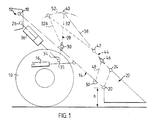
- Two substantially symmetrically positioned lift-arms 14 can be swung between a lower and an upper terminal position by means of a pair of hydraulic cylinders 16.
- the lift-arms are pivotally connected to a pivot shaft 18 mounted on the frame 12. Mounted on the outer ends of the lift-arms is a pivot shaft which forms the lower pivot shaft 20 for pivotal attachment of a work implement in the form of a bucket 22.
- the bucket has an upper pivot shaft 24 which is connected to a pivot shaft 26 on the frame 12 located beneath the shaft 18 of the lift-arms, via the aforesaid linkage system.
- This connection includes a double-lever shift-arm 28 which forms part of the linkage system and which, by a pivot journal 30, is journalled on a cross-piece extending between the lift-arms, this journalling being effected indirectly via a bracket structure.
- the shift-arm has an upper, and longer lever 32 and a lower, and shorter lever 34.
- one single tilt-cylinder 36 Connected between the fixed pivot shaft 26 and the pivot pin 35 of the lower lever 34 is one single tilt-cylinder 36, which functions as a length-extensible link for adjusting the implement 22 to desired angular positions in relation to the horizontal plane.
- a link arrangement which includes a longer link 38, one end of which is connected to the pivot pin 40 of the upper, longer lever 32, and the other end of which is connected to one end of a shorter link 44, via a pivot connection 42, whereas the other end of said shorter link is connected to the upper pivot shaft 24 of the work implement.
- pivot connection 46 for the upper end of a pivot lever 48, the lower end of which is connected to the lift-arms 14 by means of a pivot connection 50.
- the link arrangement 44, 48 is known for the purpose of generating a relatively large tilting-torque on the work-implement, and it is, in principle, also known to position the tilt-cylinder between the shorter lever 34 and the frame 12.
- these components constitute a novel and useful combination by means of which the desired parallelism of both the lifting-fork and the upwardly swung bucket can be achieved with locked tilt-cylinders.
- the lengths of the different levers between their respective pivot points should have a given relationship in respect of one another.
- the relationship between the length of the long link 38, which is connected to the long lever 32 of the shifting-arm, and the length-extension of the lift-arm 14 between its pivot points 18, 20 should be in the region of 0.30-0.50, preferably about 0.40.
- the relationship between the length of the link 38 and the distance between the pivot point 30 of the shift-arm and the lower pivot point 50 of the pivot lever 48 should be in the region of 0.8-1.1, preferably about 0.9.
- the relationship between the length-extension located between the inner pivot point 18 of the lift arm and the pivot shaft 30 of the shift-arm and the length of the lift-arm 14 should be in the region of 0.4-0.5, preferably approximately in the middle of this range.
- the ratio between the length of this lever and the length of the lift-arm 14 will preferably be in the region of 0.1-0.2.
- the relationship between the length of the long lever 32 of the shift-arm and the length of its short lever 34 will then preferably lie within the range of 2.0-2.3.
- pivot point 26 which is essentially common to the fork linkage system and bucket linkage system respectively.
- the pivot point 40 will perform different movements in relation to the lift-arm 14, depending on the length extension of the tilt-cylinder 36 when the cylinder is locked in position.
- the cylinder is adjusted essentially to its central position, in order to obtain fork-parallelism, whereas the cylinder is extended to a given position when the implement concerned is a bucket which shall move in parallelism when being lifted from an upwardly swung position.
- the cylinder is extended to a given position when the implement concerned is a bucket which shall move in parallelism when being lifted from an upwardly swung position.
- the reference 32A identifies an alternative upper-lever position which affords a larger angle between the levers and the changed conditions around the circle 52 described by the pivot point 40 as the shift-arm is swung.
- the angle to which the shift-arm is adjusted can be selected so as to influence the relationship between the torque generated by rotation of the tilt-cylinder 36 and the long link 32 about the pivot shaft 30.
- a high braking-torque when the bucket digs into the ground at the cost of a lower torque when emptying the bucket at a high, elevated level.
- the inventive linkage system enables the system to be adapted for different types of work and different desiderata associated therewith with the aid of simple means, therewith rendering the inventive linkage system highly versatile.
- Fig. 2 illustrates schematically the various positions of the linkage system for achieving essentially parallel-movement of a lifting fork 54.
- Fig. 3 illustrates the various positions of the linkage system for achieving essentially parallel-movement of the bucket 22.
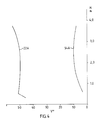
- Fig. 4 is a diagram which presents a curve 54A illustrating the fork-angle changes, V-degrees, which occur when the fork is raised given in meters h , whereas the curve 22A illustrates the bucket-angle changes, V-degrees, in an upwardly swung position while being lifted through h meters.
- the system can be adjusted so that the curve 22A will be a substantially straight vertical line, although the curvature of the line 54A will then be more pronounced, i.e. increased variation in the bucket angle.
- the illustrated curves present a compromise with acceptable values for a locked tilt-cylinder during a lifting operation, with both fork and bucket.
- the linkage system includes only a relatively small number of components, therewith reducing manufcturing costs to a corresponding degree.
- the view from the driving seat is relatively good.
- the tilt-cylinder 36 lies low in the region between the lift-arms 14 and the shift-arm 28 and, seen from above, the long and short levers 32, 34 form relatively narrow or slim components which will not obstruct the view of the driver.
Landscapes
- Engineering & Computer Science (AREA)
- Mechanical Engineering (AREA)
- Mining & Mineral Resources (AREA)
- Civil Engineering (AREA)
- General Engineering & Computer Science (AREA)
- Structural Engineering (AREA)
- Forklifts And Lifting Vehicles (AREA)
- Shovels (AREA)
- Hinges (AREA)
- Machines For Manufacturing Corrugated Board In Mechanical Paper-Making Processes (AREA)
- Electrical Discharge Machining, Electrochemical Machining, And Combined Machining (AREA)
- Jib Cranes (AREA)
- Mechanically-Actuated Valves (AREA)
- Automobile Manufacture Line, Endless Track Vehicle, Trailer (AREA)
- Supporting Of Heads In Record-Carrier Devices (AREA)
- Vehicle Body Suspensions (AREA)
Claims (1)
- Système d'éléments articulés pour des machines de chargement du type comprenant deux bras de levage (14) aptes à pivoter entre une position extrême inférieure et une position extrême supérieure à l'aide de vérins hydrauliques (16); un outil de travail (22), tel qu'une fourche de levage de palettes ou un godet monté(e) d'une manière pivotante sur un arbre de pivotement inférieur monté sur les extrémités extérieures des bras de levage (14); un système d'éléments articulés qui relie un arbre de pivotement supérieur (24) de l'outil à un arbre de pivotement fixe (26) monté sur le châssis (12) de la machine, au-dessous de l'arbre de support (18) des bras de levage par l'intermédiaire d'un bras de déplacement (28) à deux leviers supporté sur les bras de levage, directement ou indirectement, et comportant des leviers supérieur et inférieur (32 et 34, respectivement), au moins un vérin d'inclinaison (36) qui définit un élément de liaison ayant une longueur d'extension réglable de manière à permettre de procéder à des ajustements de l'angle de l'outil par rapport au plan horizontal, et un dispositif articulé (44, 48) situé au niveau de la partie d'extrémité avant des bras de levage et reliant le levier supérieur (32) du bras de déplacement à l'arbre de pivotement supérieur (24) de l'outil de travail, étant précisé que le levier inférieur et plus court (34) du bras de déplacement (28) est relié à l'arbre de pivotement fixe (26) du système, monté sur le châssis, par un seul vérin d'inclinaison (36) positionné centralement entre les bras de levage (14); que la liaison entre le levier supérieur et plus long (32) du bras de déplacement et l'arbre de pivotement supérieur (24) de l'outil (22) se compose d'un premier élément articulé (38) dont l'extrémité avant est reliée d'une manière pivotante à un second élément articulé (44) faisant partie du dispositif articulé; que le second élément articulé porte, d'une manière approximativement centrale entre ses extrémités, un levier pivotant (48) dont l'extrémité supérieure est reliée d'une manière pivotante (46) au second élément articulé et dont l'extrémité inférieure est reliée d'une manière pivotante (50) aux bras de levage, directement ou indirectement, caractérisé en ce que le second élément articulé (44) est plus court que le premier élément articulé (38); en ce que le rapport entre la longueur de l'élément articulé long (38) relié au levier long (32) du bras de déplacement, et la longueur du bras de levage (14) entre ses points de pivotement (18, 20) se situe dans la plage de 0,30 à 0,50, de préférence autour de 0,40; en ce que le rapport entre la longueur de l'élément articulé (38) et la distance entre le point de pivotement (30) du bras de déplacement et le point de pivotement inférieur (50) du levier pivotant (48) se situe dans la plage de 0,8 à 1,1, de préférence autour de 0,9; en ce que le rapport entre la longueur entre le point de pivotement intérieur (18) du bras de levage et l'arbre de pivotement (30) du bras de déplacement et la longueur du bras de levage (14) se situe dans la plage de 0,4 à 0,5, de préférence autour du milieu de cette plage; en ce que le rapport entre la longueur du levier inférieur et plus court (34) du bras de déplacement et la longueur du bras de levage (14) se situe à l'intérieur de la plage de 0,1 à 0,2; et en ce que le rapport entre la longueur du levier supérieur et plus long (32) du bras de déplacement et la longueur du levier inférieur et plus court (34) dudit bras de déplacement se situe dans la plage de 2,0 à 2,3.
Applications Claiming Priority (3)
| Application Number | Priority Date | Filing Date | Title |
|---|---|---|---|
| SE8804403A SE462624B (sv) | 1988-12-06 | 1988-12-06 | Laenkarmsystem vid lastmaskiner |
| SE8804403 | 1988-12-06 | ||
| PCT/SE1989/000675 WO1990006403A1 (fr) | 1988-12-06 | 1989-11-21 | Systeme d'elements articules pour des machines de chargement |
Publications (2)
| Publication Number | Publication Date |
|---|---|
| EP0447422A1 EP0447422A1 (fr) | 1991-09-25 |
| EP0447422B1 true EP0447422B1 (fr) | 1994-09-21 |
Family
ID=20374162
Family Applications (1)
| Application Number | Title | Priority Date | Filing Date |
|---|---|---|---|
| EP89913264A Expired - Lifetime EP0447422B1 (fr) | 1988-12-06 | 1989-11-21 | Systeme d'elements articules pour des machines de chargement |
Country Status (10)
| Country | Link |
|---|---|
| US (1) | US5156520A (fr) |
| EP (1) | EP0447422B1 (fr) |
| JP (1) | JP2784257B2 (fr) |
| AT (1) | ATE111996T1 (fr) |
| BR (1) | BR8907787A (fr) |
| DE (1) | DE68918456T2 (fr) |
| ES (1) | ES2059833T3 (fr) |
| FI (1) | FI97248C (fr) |
| SE (1) | SE462624B (fr) |
| WO (1) | WO1990006403A1 (fr) |
Families Citing this family (17)
| Publication number | Priority date | Publication date | Assignee | Title |
|---|---|---|---|---|
| US5188502A (en) * | 1990-12-24 | 1993-02-23 | Caterpillar, Inc. | Linkage arrangement for a multi-purpose vehicle |
| JPH04131574U (ja) * | 1991-05-29 | 1992-12-03 | 谷電機工業株式会社 | 重心保持と重心移動機能付運搬装置 |
| DE4211078C2 (de) * | 1992-04-03 | 1995-05-24 | Orenstein & Koppel Ag | Hubwerk für Arbeitsgeräte an Ladefahrzeugen |
| US5201235A (en) * | 1992-04-20 | 1993-04-13 | Caterpillar Inc. | Linkage for loader bucket or other material handling device |
| US5984618A (en) * | 1997-06-30 | 1999-11-16 | Caterpillar Inc. | Box boom loader mechanism |
| DE19800164A1 (de) * | 1998-01-05 | 1999-07-22 | Orenstein & Koppel Ag | Mobile Lademaschine mit Frontladeausrüstung |
| US6409459B1 (en) | 1998-01-30 | 2002-06-25 | Caterpillar Inc. | Linkage assembly for connecting a work implement to a frame of a work machine |
| US6116847A (en) * | 1998-01-30 | 2000-09-12 | Caterpillar Inc. | Lift arm for a work machine having extended height and enhanced stability |
| US7736117B2 (en) * | 2007-10-31 | 2010-06-15 | Caterpillar Inc. | Linkage assembly |
| US8662816B2 (en) | 2010-11-18 | 2014-03-04 | Caterpillar Inc. | Z-bar linkage for wheel loader machines |
| KR101778308B1 (ko) | 2011-12-27 | 2017-09-27 | 두산인프라코어 주식회사 | 건설중장비용 병렬 링키지 타입 작업장치 |
| US9303383B2 (en) | 2012-07-06 | 2016-04-05 | Caterpillar Inc. | Lift arm cross member |
| US10626576B2 (en) | 2016-12-16 | 2020-04-21 | Clark Equipment Company | Loader with telescopic lift arm |
| USD832552S1 (en) | 2017-10-12 | 2018-10-30 | Clark Equipment Company | Lift arm for loader |
| USD832551S1 (en) | 2017-10-12 | 2018-10-30 | Clark Equipment Company | Loader |
| US11035094B1 (en) | 2020-01-10 | 2021-06-15 | Ferguson Trailer Transport, Inc. | Device and method for extending material mover reach |
| DE102020110187B4 (de) * | 2020-04-14 | 2026-03-05 | Danfoss Power Solutions Inc. | Verbesserte Hydraulikvorrichtung |
Family Cites Families (10)
| Publication number | Priority date | Publication date | Assignee | Title |
|---|---|---|---|---|
| US2817448A (en) * | 1955-01-24 | 1957-12-24 | John S Pilch | Material handling device |
| US3001654A (en) * | 1957-08-30 | 1961-09-26 | Pettibone Mulliken Corp | Reaching and self-leveling loader |
| DE1231163B (de) * | 1962-07-12 | 1966-12-22 | Caterpillar Tractor Co | An einem Kraftfahrzeug angeordnete Ladeeinrichtung |
| GB1086682A (en) * | 1964-04-23 | 1967-10-11 | F E Weatherill Ltd | Improvements in or relating to shovel-loaders |
| FR1523548A (fr) * | 1967-04-20 | 1968-05-03 | Maschf Augsburg Nuernberg Ag | Pelle mécanique mobile pouvant être utilisée en marche ou à poste fixe |
| US3786953A (en) * | 1972-11-16 | 1974-01-22 | Allis Chalmers | Loader linkage |
| DE2948480C2 (de) * | 1979-12-01 | 1983-12-22 | Hanomag GmbH, 3000 Hannover | Auslegergestänge für einen Schaufellader |
| US4364705A (en) * | 1980-07-07 | 1982-12-21 | J. I. Case Company | Loader mechanism |
| US4609322A (en) * | 1984-08-13 | 1986-09-02 | Caterpillar Tractor Co. | Mounting for a linkage arrangement |
| US4601634A (en) * | 1985-09-06 | 1986-07-22 | Westendorf Manufacturing Company, Inc. | Cylinder strain relief linkage for a loader device for a tractor or the like |
-
1988
- 1988-12-06 SE SE8804403A patent/SE462624B/sv not_active IP Right Cessation
-
1989
- 1989-11-21 AT AT89913264T patent/ATE111996T1/de not_active IP Right Cessation
- 1989-11-21 ES ES89913264T patent/ES2059833T3/es not_active Expired - Lifetime
- 1989-11-21 DE DE68918456T patent/DE68918456T2/de not_active Expired - Lifetime
- 1989-11-21 EP EP89913264A patent/EP0447422B1/fr not_active Expired - Lifetime
- 1989-11-21 US US07/678,346 patent/US5156520A/en not_active Expired - Lifetime
- 1989-11-21 BR BR898907787A patent/BR8907787A/pt not_active IP Right Cessation
- 1989-11-21 JP JP2500270A patent/JP2784257B2/ja not_active Expired - Lifetime
- 1989-11-21 WO PCT/SE1989/000675 patent/WO1990006403A1/fr not_active Ceased
-
1991
- 1991-06-05 FI FI912700A patent/FI97248C/fi active
Also Published As
| Publication number | Publication date |
|---|---|
| FI97248C (fi) | 1996-11-11 |
| SE462624B (sv) | 1990-07-30 |
| ATE111996T1 (de) | 1994-10-15 |
| SE8804403L (sv) | 1990-06-07 |
| EP0447422A1 (fr) | 1991-09-25 |
| ES2059833T3 (es) | 1994-11-16 |
| WO1990006403A1 (fr) | 1990-06-14 |
| BR8907787A (pt) | 1991-08-27 |
| DE68918456D1 (de) | 1994-10-27 |
| FI912700A0 (fi) | 1991-06-05 |
| DE68918456T2 (de) | 1995-01-19 |
| JP2784257B2 (ja) | 1998-08-06 |
| US5156520A (en) | 1992-10-20 |
| FI97248B (fi) | 1996-07-31 |
| JPH04501748A (ja) | 1992-03-26 |
Similar Documents
| Publication | Publication Date | Title |
|---|---|---|
| US5156520A (en) | Linkage system for loading machines | |
| CN100429357C (zh) | 滑动转向装卸机 | |
| US4077140A (en) | Hydraulic excavator equipment for excavation laterally of the excavator | |
| EP3051031B1 (fr) | Chargeuse à roues avec un dispositif de levage | |
| US4201268A (en) | Adjustment mechanism for dozer blade | |
| US20050102866A1 (en) | Multi-function work machine | |
| US3586195A (en) | Digging and lifting device | |
| US10633819B2 (en) | Self-level mechanism for a construction machine | |
| US2775831A (en) | Tool adjustment for earth working machines | |
| US4364705A (en) | Loader mechanism | |
| US3880243A (en) | Road building machine with two adjustable work implements | |
| CN111997114A (zh) | 角度可调式平动举升机械 | |
| EP0474210B1 (fr) | Flèche de chargeuse à montée verticale | |
| JPS6342050B2 (fr) | ||
| US4372729A (en) | Tilt control | |
| JP2000509348A (ja) | 支持アームを具備する走行可能な作業機械 | |
| US4316697A (en) | Front-loading hydraulic excavator | |
| US3291330A (en) | Power loader | |
| KR102709915B1 (ko) | 유압승강식 도저와 다짐기구가 구비된 건설장비 | |
| GB2049383A (en) | Scarifier | |
| JPH05295754A (ja) | 油圧式掘削機の作業機操作装置 | |
| JPH1052129A (ja) | 乗用型田植機 | |
| WO2019144687A1 (fr) | Chargeur à levage vertical | |
| KR200296570Y1 (ko) | 좌우측 각도조절이 가능한 굴삭기 아암. | |
| JP2002339389A (ja) | 作業用走行車 |
Legal Events
| Date | Code | Title | Description |
|---|---|---|---|
| PUAI | Public reference made under article 153(3) epc to a published international application that has entered the european phase |
Free format text: ORIGINAL CODE: 0009012 |
|
| 17P | Request for examination filed |
Effective date: 19910420 |
|
| AK | Designated contracting states |
Kind code of ref document: A1 Designated state(s): AT BE CH DE ES FR GB IT LI LU NL |
|
| 17Q | First examination report despatched |
Effective date: 19930312 |
|
| GRAA | (expected) grant |
Free format text: ORIGINAL CODE: 0009210 |
|
| ITF | It: translation for a ep patent filed | ||
| AK | Designated contracting states |
Kind code of ref document: B1 Designated state(s): AT BE CH DE ES FR GB IT LI LU NL |
|
| REF | Corresponds to: |
Ref document number: 111996 Country of ref document: AT Date of ref document: 19941015 Kind code of ref document: T |
|
| REF | Corresponds to: |
Ref document number: 68918456 Country of ref document: DE Date of ref document: 19941027 |
|
| ET | Fr: translation filed | ||
| REG | Reference to a national code |
Ref country code: ES Ref legal event code: FG2A Ref document number: 2059833 Country of ref document: ES Kind code of ref document: T3 |
|
| PLBE | No opposition filed within time limit |
Free format text: ORIGINAL CODE: 0009261 |
|
| STAA | Information on the status of an ep patent application or granted ep patent |
Free format text: STATUS: NO OPPOSITION FILED WITHIN TIME LIMIT |
|
| 26N | No opposition filed | ||
| REG | Reference to a national code |
Ref country code: GB Ref legal event code: IF02 |
|
| REG | Reference to a national code |
Ref country code: CH Ref legal event code: PFA Owner name: VME INDUSTRIES SWEDEN AB Free format text: VME INDUSTRIES SWEDEN AB# #ESKILSTUNA (SE) -TRANSFER TO- VME INDUSTRIES SWEDEN AB# #ESKILSTUNA (SE) |
|
| PGFP | Annual fee paid to national office [announced via postgrant information from national office to epo] |
Ref country code: NL Payment date: 20081103 Year of fee payment: 20 Ref country code: CH Payment date: 20081130 Year of fee payment: 20 Ref country code: DE Payment date: 20081114 Year of fee payment: 20 Ref country code: LU Payment date: 20081203 Year of fee payment: 20 |
|
| PGFP | Annual fee paid to national office [announced via postgrant information from national office to epo] |
Ref country code: ES Payment date: 20081216 Year of fee payment: 20 Ref country code: AT Payment date: 20081112 Year of fee payment: 20 |
|
| PGFP | Annual fee paid to national office [announced via postgrant information from national office to epo] |
Ref country code: IT Payment date: 20081126 Year of fee payment: 20 Ref country code: BE Payment date: 20081110 Year of fee payment: 20 |
|
| PGFP | Annual fee paid to national office [announced via postgrant information from national office to epo] |
Ref country code: FR Payment date: 20081112 Year of fee payment: 20 |
|
| PGFP | Annual fee paid to national office [announced via postgrant information from national office to epo] |
Ref country code: GB Payment date: 20081119 Year of fee payment: 20 |
|
| BE20 | Be: patent expired |
Owner name: *VME INDUSTRIES SWEDEN A.B. Effective date: 20091121 |
|
| REG | Reference to a national code |
Ref country code: CH Ref legal event code: PL |
|
| REG | Reference to a national code |
Ref country code: GB Ref legal event code: PE20 Expiry date: 20091120 |
|
| REG | Reference to a national code |
Ref country code: ES Ref legal event code: FD2A Effective date: 20091123 |
|
| NLV7 | Nl: ceased due to reaching the maximum lifetime of a patent |
Effective date: 20091121 |
|
| PG25 | Lapsed in a contracting state [announced via postgrant information from national office to epo] |
Ref country code: NL Free format text: LAPSE BECAUSE OF EXPIRATION OF PROTECTION Effective date: 20091121 |
|
| PG25 | Lapsed in a contracting state [announced via postgrant information from national office to epo] |
Ref country code: GB Free format text: LAPSE BECAUSE OF EXPIRATION OF PROTECTION Effective date: 20091120 Ref country code: ES Free format text: LAPSE BECAUSE OF EXPIRATION OF PROTECTION Effective date: 20091123 |