EP0450776A1 - Structure de jointoiement pour fixer des panneaux en forme de blocs sur le mur latéral d'un bâtiment - Google Patents
Structure de jointoiement pour fixer des panneaux en forme de blocs sur le mur latéral d'un bâtiment Download PDFInfo
- Publication number
- EP0450776A1 EP0450776A1 EP91302138A EP91302138A EP0450776A1 EP 0450776 A1 EP0450776 A1 EP 0450776A1 EP 91302138 A EP91302138 A EP 91302138A EP 91302138 A EP91302138 A EP 91302138A EP 0450776 A1 EP0450776 A1 EP 0450776A1
- Authority
- EP
- European Patent Office
- Prior art keywords
- panel block
- stud means
- joint structure
- building
- blind bore
- Prior art date
- Legal status (The legal status is an assumption and is not a legal conclusion. Google has not performed a legal analysis and makes no representation as to the accuracy of the status listed.)
- Granted
Links
- 239000000853 adhesive Substances 0.000 description 4
- 230000001070 adhesive effect Effects 0.000 description 4
- 239000002184 metal Substances 0.000 description 4
- 229910052751 metal Inorganic materials 0.000 description 4
- XEEYBQQBJWHFJM-UHFFFAOYSA-N Iron Chemical compound [Fe] XEEYBQQBJWHFJM-UHFFFAOYSA-N 0.000 description 2
- 239000004567 concrete Substances 0.000 description 2
- 238000005034 decoration Methods 0.000 description 2
- 238000005516 engineering process Methods 0.000 description 2
- 239000000945 filler Substances 0.000 description 2
- 239000004579 marble Substances 0.000 description 2
- 239000000463 material Substances 0.000 description 2
- 239000004570 mortar (masonry) Substances 0.000 description 2
- 230000002093 peripheral effect Effects 0.000 description 2
- 239000004575 stone Substances 0.000 description 2
- 229910000831 Steel Inorganic materials 0.000 description 1
- 238000013459 approach Methods 0.000 description 1
- 239000002969 artificial stone Substances 0.000 description 1
- 239000004568 cement Substances 0.000 description 1
- 230000003247 decreasing effect Effects 0.000 description 1
- 230000006866 deterioration Effects 0.000 description 1
- 238000005553 drilling Methods 0.000 description 1
- 239000011521 glass Substances 0.000 description 1
- 229910052742 iron Inorganic materials 0.000 description 1
- 238000012986 modification Methods 0.000 description 1
- 230000004048 modification Effects 0.000 description 1
- 238000005192 partition Methods 0.000 description 1
- 239000011150 reinforced concrete Substances 0.000 description 1
- 229910001220 stainless steel Inorganic materials 0.000 description 1
- 239000010935 stainless steel Substances 0.000 description 1
- 239000010959 steel Substances 0.000 description 1
- -1 tile Substances 0.000 description 1
Images


Classifications
-
- E—FIXED CONSTRUCTIONS
- E04—BUILDING
- E04F—FINISHING WORK ON BUILDINGS, e.g. STAIRS, FLOORS
- E04F13/00—Coverings or linings, e.g. for walls or ceilings
- E04F13/07—Coverings or linings, e.g. for walls or ceilings composed of covering or lining elements; Sub-structures therefor; Fastening means therefor
- E04F13/08—Coverings or linings, e.g. for walls or ceilings composed of covering or lining elements; Sub-structures therefor; Fastening means therefor composed of a plurality of similar covering or lining elements
- E04F13/0801—Separate fastening elements
- E04F13/0832—Separate fastening elements without load-supporting elongated furring elements between wall and covering elements
- E04F13/0853—Separate fastening elements without load-supporting elongated furring elements between wall and covering elements adjustable perpendicular to the wall
- E04F13/0855—Separate fastening elements without load-supporting elongated furring elements between wall and covering elements adjustable perpendicular to the wall adjustable in several directions, one of which is perpendicular to the wall
-
- E—FIXED CONSTRUCTIONS
- E04—BUILDING
- E04F—FINISHING WORK ON BUILDINGS, e.g. STAIRS, FLOORS
- E04F13/00—Coverings or linings, e.g. for walls or ceilings
- E04F13/07—Coverings or linings, e.g. for walls or ceilings composed of covering or lining elements; Sub-structures therefor; Fastening means therefor
- E04F13/08—Coverings or linings, e.g. for walls or ceilings composed of covering or lining elements; Sub-structures therefor; Fastening means therefor composed of a plurality of similar covering or lining elements
- E04F13/14—Coverings or linings, e.g. for walls or ceilings composed of covering or lining elements; Sub-structures therefor; Fastening means therefor composed of a plurality of similar covering or lining elements stone or stone-like materials, e.g. ceramics concrete; of glass or with an outer layer of stone or stone-like materials or glass
- E04F13/144—Coverings or linings, e.g. for walls or ceilings composed of covering or lining elements; Sub-structures therefor; Fastening means therefor composed of a plurality of similar covering or lining elements stone or stone-like materials, e.g. ceramics concrete; of glass or with an outer layer of stone or stone-like materials or glass with an outer layer of marble or other natural stone
Definitions
- the present invention relates to a joint structure for fixing plural panel blocks on an exterior or interior wall or a building.
- Each panel block has a bore extending vertically from the edge end face, and a connection screw is inserted through a threaded hole provided through the connector member to extend into the bore of the panel block, the connection screw having a head, a threaded portion vicinal to the head and a pin portion provided in front of the threaded portion.
- the gap between the bore of the panel block and the connection crew is filled with an adhesive so that the connection screw is fixed into the bore of the panel block.
- An object of this invention is to provide a joint structure for fixing panel blocks on a wall of a building in such a manner that the lower edge face of each panel block contacts closely with the upper edge face of the lower adjacent panel block not to leave gaps therebetween.
- Another object of this invention is to provide such a joint structure which can be handled with ease.
- the present invention provides a joint structure for fixing panel blocks on a side wall of a building in a manner such that the lower edge face of each panel block contacts closely with the upper edge face of the lower adjacent panel block, each panel block having a first blind bore extending vertically from the lower edge face thereof and a second blind bore extending vertically from the upper edge face thereof, said joint structure comprising first stud means anchored to said side wall of said building and having an exposed end extending beyond the surface of said side wall of said building, second stud means anchored to each panel block and having an exposed end extending beyond the interior surface of each panel block, a positioning rod having one end inserted into said first blind bore of upper adjacent panel block and the other end inserted into said second blind 1 bore of lower adjacent panel block, said positioning rod being pressed by the inner end of said second stud means to be fixedly held in position, and connector means having one end connected to said exposed end of said first stud means and the other end connected to said exposed end of said second stud means.
- the second stud means comprises a cylindrical anchor member having a threaded center bore and a slitted end and a male secrew member inserted into said threaded center bore of said cylindrical anchor member, whereby the anchor member can be fitted to the panel block under pressure to be securely fitted.
- the second stud means comprises an anchor member having a ring-shaped cross section to be received in a ring-shaped anchor bore formed in each panel block.
- the second stud means comprises an anchor member having an end of generally flat disk shape to be received in a concaved slot of said panel block extending generally in the horizontal direction.
- Fig. 1 is a sectional view showing a first embodiment of the invention
- Fig. 2 is a perspective view of the first embodiment with parts cut away for easy understanding
- Fig. 3 is a sectional view of the first embodiment
- Fig. 4 is a sectional view showing the details of the second stud means of the first embodiment
- Fig. 5 is a perspective view of the connector means used in the first embodiment
- Fig. 6 is a sectional view showing the joint structure for fixing the lowermost panel block in the first embodiment
- Fig. 7 is a perspective view of a second embodiment with portions cut away for easy understanding
- Fig. 8 is a sectional view of the second embodiment
- Fig. 9 is a perspective view of a third embodiment with portions cut away for easy understanding
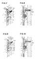
- Fig. 10 is a sectional view of the third embodiment
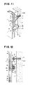
- Fig. 11 is a perspective view of a fourth embodiment with portions cut away for easy understanding
- Fig. 12 is a sectional view of the fourth embodiment.
- Plural panel blocks 1 made of, for example, marble or natural stone are piled one after another to cover a outer side wall 3 of a concrete building 2.
- Each panel block 1 is formed with a bore 4 extending from the interior surface at the upper portion thereof.
- Each panel block also provided with a first blind bore 6 extending vertically from the lower edge face 8 and a second blind bore 5 extending vertically from the upper edge face 7.
- the first blind bore 6 of an upper adjacent panel block and the second blind bore 5 of a lower adjacent panel block are agreed with each other to form a substantially straight and continuous bore when these blocks are piled one on the another.
- An anchor member 9 is inserted into the bore 4, and has a generally cylindrical body 10 having a center bore formed with an internal thread 11. The end of the thread is enlarged to form an enlarged cavity 12. As best seen from Fig. 3, the inner half of the enlarged cavity 12 is defined by symmetrical tapered walls 13 which are converged with each other. A slitted hole 14 is formed at the fore end of the cylindrical body 10 so that the fore end of the anchor member 9 is bifurcated. A vertical through-hole 15 is formed at a portion of the enlarged cavity 12 so that this vertical hole 15 extends coaxially with the second blind bore 5.
- a male screw member 16 is threaded into the internal thread 11 of the anchor member 9, and a square projection 15A is formed on the exposed end of the male screw member 16 for engaging with a tool (not shown).
- a first stud means 17 is formed by the combination of the male screw memeber 16 and the anchor member 9.
- the anchor member 19 is provided with an internal thread 20, and a male screw member 21 is threaded into the internal thread 20 to serve as the first stud means.
- Connector means 22 has one end connected to the male screw member 21 and has the other end connected to the male screw member 16.
- the upper plate portion of the connector means 22 is provided with an elongated hole 23 and the lower plate portion of the connector means 22 is also provided with an elongated hole 24, so that both ends of the connector means 22 can be connected to the male screw members 16 and 19 while adjusting its position along the horizontal and vertical directions relative to the male screw members 16 and 19.
- Reference numerals 25 and 26 designate nuts which are meshed with the male screw members 16 and 21, and reference numeral 27 designates a washer.
- the lowermost panel block 1A is supported by a support assembly 28 which comprises a first support member 31 having an L-shaped section and a second support member 32 having a bent projection at one end thereof.
- a support assembly 28 which comprises a first support member 31 having an L-shaped section and a second support member 32 having a bent projection at one end thereof.
- one leg of the first support member 31 is engaged with the surface of the wall 3 of the building 2 and fixed in position by means of an anchor bolt 30.
- the bent projection of the second support member 32 is inserted in the first blind bore 6 of the lowermost panel block 1A, and the other end of the second support member 32 is joined with the other leg of the first support member 31 by means of a bolt and nut pair 34 inserted through a hole 33.
- the connector means 22 and the anchor members 9 and 19 may be made of a metal, such as stainless steel.
- bores 4 are formed by drilling at proper positions of the concrete wall 3 of the building 2, and an anchor member 19 is anchored into each bore 4 and a male screw member 21 is thrusted into each anchor member 19.
- Vertically extending bores 5 and 6 are pierced from the upper and lower edge faces of each of the panel blocks 1B, 1C, and a bore 4 is formed at a proper position of the interior surface of each panel block 1.
- One anchor member 9 is inserted into each bore 4 to be fixedly anchored to the interior surface of each panel block 1, and a positioning rod 18 is inserted into the second or upper blind bore 5 to extend through the vertical through-hole 15 of the anchor member 9.
- the square projection 15A of the male screw member 16 is grasped by a wrench or like proper tool to rotate the member 16 to thrust the male screw member 16 into the internal thread 11, whereby the positioning rod 18 is pressed onto the tapered walls 13 so that the positioning rod 18 is fixed in position and simultaneously the slit 14 is pushed outwardly to prevent the anchor member 9 from slipping out of the bore 4.
- the male screw member 16 is then inserted through the elongated hole 23 of the connector means 22 and fixed by the nut 25.
- the support assembly 28 is secured on the wall 3, and then the bent projection of the second support member 32 is inserted into the lower or first vertical blind bore 6 to support the lowermost panel block 1A in position.
- the male screw member 21 is inserted through the elongated hole 24 of the connector means 22 and fixed by the nut 26 and the washer 27, thereby the lowermost panel block 1A is suspended by the wall 3 of the building 2 through the support assembly 28 and the connector means 22.
- a second panel block 1B is placed on the lowermost panel block 1A while the upper edge face 7 of the latter is faced to the lower edge face 8 of the former.
- the upper end of the positioning rod 18 projecting beyond the upper edge face 7 of the lowermost panel block 1A is inserted into the lower or first blind bore 6 of the second panel block 1B so that the exterior side faces of both panel blocks flush with each other to form a flat and smooth joined surface.
- an filler such as mortar or an adhesive
- an adhesive may be applied over the edge faces 7 and 8 to bind the adjacent panels 1A and 1B more firmly.
- each panel block 1 is suspended by the wall 3 through the connector means 22 while the lower leg of the connector means 22 contacts with the interior side face of the panel block 1, no gap is left between the adjacent panel blocks and the piled panel blocks 1 form a continuous exterior surface to improve the appearance of the finished structure.
- the positioning rod 18 is pressed onto the tapered walls 13 formed in the end portion of the anchor member 9 and fixed in position by tightening the male screw member 16, the piled panel blocks 1A, 1B, --- can be firmly assembled without the fear of tottering or other unstable condition.
- Each panel block 1 can be fixed in position by the operation sequence including the steps of inserting the male screw mamber 21 into the anchor member 19 followed by tightening the member 19, inserting the male screw member 16 into the anchor member 9 followed by tightening the member 16 to fix the positioning rod 18, fixedly connecting the lower leg of the connector means 22 to the exposed end of the male screw member 16, connecting the upper leg of the connector means 22 to the exposed end of the male screw member 21 to suspend each panel block 1, and then tightening the nut 22.
- This operation sequence does not require skillful work.
- FIG. 7 and 8 A second embodiment of this invention is shown in Figs. 7 and 8; a third embbodiment is shown in Figs. 9 and 10; and a fourth embodiment is shown in Figs. 11 and 12.
- the same parts are denoted by the same reference numerals and the description thereof will not be given for simplicity of the description.
- the stud means anchored to each panel block 1 comprises a generally cylindrical member 41 having an end portion through which a vertical through-hole 15 is formed, and a male screw member 16 having one end protruding beyond the interior surface of the panel block 1.
- the cylindrical member 41 is fixedly anchored in a bore 4A with the vertical through-hole 15 extends coaxially with the upper and lower blind bores 5 and 6 extending respectively from the upper and lower edge faces of the panel block 1.
- a male screw member 16 is inserted through the elongated hole 23 of the connector means 22 and screw-fitted with the member 16, and then the nut 25 is tightened to fix the connector means 22 in position.
- the cylindrical member 41 is drawn through the male screw member 16A toward the building 2 so that the positioning rod 18 is pressed to the wall of the lower blind bore 6 to prevent from slipping out of the bore 6 to ensure firm connection.
- the lower leg of the connector means 22 is fixedly connected to each panel block 1 by tightening the male screw member 16.
- a generally cylindrical member 41 is anchored into the bore 4A formed at a proper position on each panel block 1, the vertical through-hole 15 being formed through the end portion of the cylindrical member 41 to allow the positioning rod 18 to extend therethrough, and the male screw member 16 is screwed into the cylindrical member 41 and has the exposed end to which the connector means 22 is connected and fixed by means of the nut 25, the positioning rod 18 being fixed in position by the cylindrical member 41.
- each panel block 1 is formed with a ring-shaped anchor bore 4B and an upper blind bore 5 extends from the upper edge face in the vertical direction.
- An anchor member 42 has an anchored end having a ring-shaped section, through-holes 15 being formed through the peripheral wall of the ring-shaped section to extend coaxially with the upper blind bore 6, and a male screw end 16B extending beyond the interior surface of the panel block 1.
- Referecne numeral 42A designates a rubber cap.
- the anchor member 42 is anchored to the ring-shaped anchor bore 4B and a positioning rod 18 is inserted through the upper blind bore 5 to extend through the through-holes 15, 15 formed through the peripheral wall of the ring-shaped section of the anchor member 42. Then, the male screw end 16B is inserted through the elongated hole 23 of the connector means 22, and then the nut 25 is fitted on the male screw end 16B and tightened. As the connector means 22 is connected to each panel block 1, the anchor member 42 is drawn toward the building 2 through the nut 25 and the male screw end 16B, whereby the positioning rod 18 is pressed onto the wall of the lower blind bore 6 so that the anchor member 42 is prevented from slipping out of the bore 4B to be firmly fixed in position. The lower leg of the connector means 22 is fixed by means of the male screw end 16B so that each panel block 1 can be firmly fixed in position.
- the operation efficiency is improved and steady fixation is ensured by the combination of the anchor bore 4B having a ring-shaped section and the anchor member 42 having the anchored end of ring-shaped contour.
- the ring-shaped anchor bore 4B may be formed by using a ring-shaped drill.
- the volume of the panel material which must be removed for excavating the anchor bore 4B is decreased, as compared to the preceding embodiments where a cylindrical cavity must be excavated, to simplify the operation and to decrease the time required for forming the anchor bore 4B.
- an anchor bore 4C formed in each panel block 1 has a shape of generally flat concave or slot.
- An stud member 43 anchored into this anchor bore 4C has a flat disk-shaped end 44 to be received into the anchor bore 4C and a male screw end 16C protruding beyond the interior surface of the panel block 1.
- a through-hole 15 is formed through the disk-shaped end for allowing a positioning rod 18 to extend therethrough.
- the disk-shaped end of the stud member 43 is inserted into the anchor bore 4C formed in each panel block 1, and the positioning rod 18 is inserted into the upper blind bore 5 to extend through the through-hole 15.
- the male screw end 16C of the stud member 43 is inserted through an elongated hole 23 of connector means 22 and then a nut 25 is screw-fitted on the male screw end 16c.
- the connector means 22 is fixedly connected, by tightening the nut 25, to the panel block 1, the stud member 13 is drawn toward the building 2 so that the positioning rod 18 is pressed onto the wall of the lower blind bore 6 to prevent the stud member 43 from stripping out of the bore 4C.
- the stud member 43 is thus firmly fixed and the panel block 1 is held in position by fixedly connecting the lower leg of the connector means 22 to the male screw end 16C.
- each panel block 1 is simplified accordinging to the fourth embodiment.
- the anchor bore 4C having the flat disk-shaped end may be simply formed by cutting the side face of the panel block 1 by using a circular saw.
- the wall of the buidling may be a partition wall, a reinforced concrete pillar, an iron framework or a wooden pillar.
- the panel block may be made of glass, tile, artificial stone, cement block or china panel.
- the present invention may be applied to cover an exterior or interior wall of a building.
- a hook member fixed by an adhesive may be used.
- the male screw member used in the stud means may be replaced by a wedge.
- a rigid material such as steel, for fabricating the stud means, the positioning rod, the male screw members, the connector means, and the cylindrical anchor member.
Landscapes
- Engineering & Computer Science (AREA)
- Architecture (AREA)
- Civil Engineering (AREA)
- Structural Engineering (AREA)
- Chemical & Material Sciences (AREA)
- Ceramic Engineering (AREA)
- Finishing Walls (AREA)
- Panels For Use In Building Construction (AREA)
- Joining Of Building Structures In Genera (AREA)
- Revetment (AREA)
Applications Claiming Priority (5)
| Application Number | Priority Date | Filing Date | Title |
|---|---|---|---|
| JP3344290 | 1990-03-29 | ||
| JP33442/90 | 1990-03-29 | ||
| JP714430/90 | 1990-07-03 | ||
| JP17443090A JPH0467348A (ja) | 1990-07-03 | 1990-07-03 | ディスクの吸引検出装置 |
| SG69894A SG69894G (en) | 1990-03-29 | 1994-05-28 | Joint structure for fixing panel blocks on side wall of building |
Publications (2)
| Publication Number | Publication Date |
|---|---|
| EP0450776A1 true EP0450776A1 (fr) | 1991-10-09 |
| EP0450776B1 EP0450776B1 (fr) | 1994-01-19 |
Family
ID=27288076
Family Applications (1)
| Application Number | Title | Priority Date | Filing Date |
|---|---|---|---|
| EP91302138A Expired - Lifetime EP0450776B1 (fr) | 1990-03-29 | 1991-03-13 | Structure de jointoiement pour fixer des panneaux en forme de blocs sur le mur latéral d'un bâtiment |
Country Status (12)
| Country | Link |
|---|---|
| US (1) | US5138809A (fr) |
| EP (1) | EP0450776B1 (fr) |
| CN (1) | CN1023416C (fr) |
| AT (1) | ATE100512T1 (fr) |
| AU (1) | AU638107B2 (fr) |
| CA (1) | CA2037301C (fr) |
| DE (1) | DE69101016T2 (fr) |
| DK (1) | DK0450776T3 (fr) |
| ES (1) | ES2048558T3 (fr) |
| HK (1) | HK86294A (fr) |
| NO (1) | NO176581C (fr) |
| SG (1) | SG69894G (fr) |
Cited By (3)
| Publication number | Priority date | Publication date | Assignee | Title |
|---|---|---|---|---|
| FR2788294A1 (fr) * | 1999-01-07 | 2000-07-13 | Tecnopan | Bardage, en particulier pour batiments industriels |
| US6935083B2 (en) * | 2002-07-11 | 2005-08-30 | C. Michael Chezum | Skirting for manufactured and modular homes |
| IT202200006419A1 (it) * | 2022-03-31 | 2023-10-01 | Ev Services S R L | Sistema strutturale e mezzi di sopportazione di elementi di finitura ed isolamento interni ed esterni di edifici |
Families Citing this family (27)
| Publication number | Priority date | Publication date | Assignee | Title |
|---|---|---|---|---|
| IT224173Z2 (it) * | 1991-01-18 | 1996-02-09 | Fischer Italia Di Paolo Morasu | Elemento adattatore per dispositivi di ancoraggio di lastre per il rivestimento di pareti |
| US5535563A (en) * | 1993-01-08 | 1996-07-16 | Stone Products Corporation | Fitted manufactured stone sections |
| US5280690A (en) * | 1993-03-11 | 1994-01-25 | Edmund Hu | Wall stone plate fixing attachment |
| NO177801C (no) * | 1993-04-16 | 1995-11-22 | Joergen Gether | Monteringsbeslag for fleksibel innfesting av elementer av naturstein til vertikale vegger |
| US5680735A (en) * | 1995-03-08 | 1997-10-28 | Bates; Gary Grant | Modular buiding system |
| US6029418A (en) * | 1997-06-28 | 2000-02-29 | Wright; John T. | Wire clip mounting system for structural panels |
| IT1293574B1 (it) * | 1997-07-07 | 1999-03-08 | Oreste Lanzani | Dispositivo di collegamento e di regolazione della disposizione spaziale di due pannelli |
| US6564514B1 (en) * | 1997-10-27 | 2003-05-20 | John W. Rickards | Concealed slab fastener |
| AU2005241023A1 (en) * | 2004-04-29 | 2005-11-17 | Keystone Retaining Wall Systems, Inc. | Veneers for walls, retaining walls and the like |
| CA2527687A1 (fr) * | 2005-11-24 | 2007-05-24 | Peter Kuelker | Systeme d'installation de panneaux premoules |
| US7647732B2 (en) * | 2006-05-15 | 2010-01-19 | Rickards John W | Decorative slab corner fastener |
| CN100485149C (zh) * | 2006-08-23 | 2009-05-06 | 泓泰复合材料(江阴)有限公司 | 复合保温板无饰条和有饰条安装方法及配套压片和装饰条 |
| US7647744B2 (en) * | 2006-10-20 | 2010-01-19 | United States Gypsum Company | Acoustic isolator clip for isolating wallboard support channels from frame member |
| US20100077676A1 (en) * | 2008-10-01 | 2010-04-01 | Install/Consult, Llc | Architectural panel hanger |
| WO2010075104A2 (fr) * | 2008-12-15 | 2010-07-01 | Mohawk Carpet Corporation | Systèmes de carreaux et procédés de fabrication et d'utilisation de ceux-ci |
| GB2477539A (en) * | 2010-02-05 | 2011-08-10 | Latchways Plc | Panel Mounting System with shock absorbing deformable strut |
| US8555587B2 (en) * | 2010-05-11 | 2013-10-15 | Mitek Holdings, Inc. | Restoration anchoring system |
| CN102535807B (zh) * | 2012-02-16 | 2014-07-09 | 中建三局装饰有限公司 | 一种模块化墙面砖预粘贴结构及其施工方法 |
| WO2014005180A1 (fr) * | 2012-07-04 | 2014-01-09 | Lode Enterprises Pty Ltd | Système de plan de travail en pierre, plateau en pierre composite et procédé de fabrication de plateau en pierre composite |
| CN103255892A (zh) * | 2013-05-09 | 2013-08-21 | 陈发城 | 饰面板或石材幕墙的安装装置及其干挂的施工方法 |
| CN103410257B (zh) * | 2013-08-01 | 2015-07-15 | 斯泰科技(杭州)有限公司 | 一种耐疲劳长效背铆栓及幕墙板的连接结构 |
| CN103899065A (zh) * | 2014-03-24 | 2014-07-02 | 上海汇辽建筑装饰工程有限公司 | 一种仿天然石板的连接机构及其安装方法 |
| CN104358376A (zh) * | 2014-10-28 | 2015-02-18 | 苏州金螳螂建筑装饰股份有限公司 | 无龙骨石材干挂结构 |
| CN105672539B (zh) * | 2016-01-07 | 2018-05-04 | 陈晓通 | 一种石材背栓挂件及其使用方法 |
| ES2559328B1 (es) * | 2016-01-20 | 2016-11-16 | Carlos Fradera Pellicer | Sistema de revestimiento de fachada |
| CN108385882A (zh) * | 2018-01-25 | 2018-08-10 | 广州珠江工程建设监理有限公司 | 一种大型龙骨拉结石材的搭接方法 |
| US10900238B2 (en) | 2018-11-05 | 2021-01-26 | Hunter Douglas Inc. | Coupling system for mounting tiles to a building |
Citations (6)
| Publication number | Priority date | Publication date | Assignee | Title |
|---|---|---|---|---|
| US1890532A (en) * | 1931-06-08 | 1932-12-13 | Insolo Holding Company | Building block and wall form |
| US3248836A (en) * | 1963-06-17 | 1966-05-03 | Structural Clay Products Inst | External wall panel and wall formed therefrom |
| DE3044453A1 (de) * | 1980-11-26 | 1982-06-24 | Karl Heinrich 6326 Romrod Schäfer | Spreizduebel |
| DE3306609A1 (de) * | 1983-02-25 | 1984-09-06 | Anton 7107 Neckarsulm Bauer | Plattenelement fuer boden- und wandflaechen |
| FR2622430A1 (fr) * | 1987-10-30 | 1989-05-05 | Laboureau Jacques | Agrafe chirurgicale pour la fixation immediate de ligaments artificiels et instrument ancillaire pour son implantation dans l'os |
| DE3819164A1 (de) * | 1988-06-04 | 1989-12-07 | Hans Schmidlin | Verkleidungstafel fuer aussenverkleidungen oder innenausbau |
Family Cites Families (11)
| Publication number | Priority date | Publication date | Assignee | Title |
|---|---|---|---|---|
| US472095A (en) * | 1892-04-05 | Island | ||
| US2130531A (en) * | 1936-08-14 | 1938-09-20 | Alfred F Arand | Structural anchor |
| US3353312A (en) * | 1966-05-11 | 1967-11-21 | Storch Bernard | Adjustable anchoring means for masonry walls |
| US3715850A (en) * | 1971-08-25 | 1973-02-13 | J Chambers | Adjustable mounting device |
| US4021989A (en) * | 1976-01-27 | 1977-05-10 | Hohmann & Barnard, Inc. | Rotatably pivotal stone anchor and stone anchor construction system |
| US4060951A (en) * | 1976-09-15 | 1977-12-06 | Sandor Gere | Stressless suspension and anchoring process of stone veneer |
| FR2522049A1 (fr) * | 1982-02-25 | 1983-08-26 | Guerin Gabriel | Dispositif de fixation d'un revetement en plaques de pierre reconstituee sur une structure murale |
| DE3333954A1 (de) * | 1983-09-20 | 1985-04-04 | Hilti Ag, Schaan | Verstellbare haltevorrichtung fuer verkleidungsplatten |
| DE3530694A1 (de) * | 1985-08-28 | 1987-04-02 | Siegfried Fricker | Vorrichtung zur verankerung von platten |
| DE3611072A1 (de) * | 1986-04-03 | 1987-10-08 | Siegfried Fricker | Vorrichtung zur verankerung von platten |
| DE3717816C2 (de) * | 1987-01-13 | 1993-10-14 | Unistrut Europ Plc Bedford | Halte- und Traganker |
-
1990
- 1990-09-11 US US07/580,884 patent/US5138809A/en not_active Expired - Fee Related
-
1991
- 1991-02-28 CA CA002037301A patent/CA2037301C/fr not_active Expired - Fee Related
- 1991-03-06 AU AU72672/91A patent/AU638107B2/en not_active Ceased
- 1991-03-08 NO NO910915A patent/NO176581C/no unknown
- 1991-03-12 CN CN91101593A patent/CN1023416C/zh not_active Expired - Fee Related
- 1991-03-13 DK DK91302138.2T patent/DK0450776T3/da active
- 1991-03-13 ES ES91302138T patent/ES2048558T3/es not_active Expired - Lifetime
- 1991-03-13 DE DE69101016T patent/DE69101016T2/de not_active Expired - Fee Related
- 1991-03-13 EP EP91302138A patent/EP0450776B1/fr not_active Expired - Lifetime
- 1991-03-13 AT AT91302138T patent/ATE100512T1/de not_active IP Right Cessation
-
1994
- 1994-05-28 SG SG69894A patent/SG69894G/en unknown
- 1994-08-25 HK HK86294A patent/HK86294A/en not_active IP Right Cessation
Patent Citations (6)
| Publication number | Priority date | Publication date | Assignee | Title |
|---|---|---|---|---|
| US1890532A (en) * | 1931-06-08 | 1932-12-13 | Insolo Holding Company | Building block and wall form |
| US3248836A (en) * | 1963-06-17 | 1966-05-03 | Structural Clay Products Inst | External wall panel and wall formed therefrom |
| DE3044453A1 (de) * | 1980-11-26 | 1982-06-24 | Karl Heinrich 6326 Romrod Schäfer | Spreizduebel |
| DE3306609A1 (de) * | 1983-02-25 | 1984-09-06 | Anton 7107 Neckarsulm Bauer | Plattenelement fuer boden- und wandflaechen |
| FR2622430A1 (fr) * | 1987-10-30 | 1989-05-05 | Laboureau Jacques | Agrafe chirurgicale pour la fixation immediate de ligaments artificiels et instrument ancillaire pour son implantation dans l'os |
| DE3819164A1 (de) * | 1988-06-04 | 1989-12-07 | Hans Schmidlin | Verkleidungstafel fuer aussenverkleidungen oder innenausbau |
Cited By (3)
| Publication number | Priority date | Publication date | Assignee | Title |
|---|---|---|---|---|
| FR2788294A1 (fr) * | 1999-01-07 | 2000-07-13 | Tecnopan | Bardage, en particulier pour batiments industriels |
| US6935083B2 (en) * | 2002-07-11 | 2005-08-30 | C. Michael Chezum | Skirting for manufactured and modular homes |
| IT202200006419A1 (it) * | 2022-03-31 | 2023-10-01 | Ev Services S R L | Sistema strutturale e mezzi di sopportazione di elementi di finitura ed isolamento interni ed esterni di edifici |
Also Published As
| Publication number | Publication date |
|---|---|
| AU7267291A (en) | 1991-10-03 |
| NO176581C (no) | 1995-04-26 |
| SG69894G (en) | 1994-10-14 |
| DE69101016D1 (de) | 1994-03-03 |
| CN1055215A (zh) | 1991-10-09 |
| DE69101016T2 (de) | 1994-05-26 |
| CA2037301A1 (fr) | 1991-09-30 |
| NO910915D0 (no) | 1991-03-08 |
| DK0450776T3 (da) | 1994-03-07 |
| US5138809A (en) | 1992-08-18 |
| HK86294A (en) | 1994-09-02 |
| CN1023416C (zh) | 1994-01-05 |
| ES2048558T3 (es) | 1994-03-16 |
| AU638107B2 (en) | 1993-06-17 |
| NO910915L (no) | 1991-09-30 |
| CA2037301C (fr) | 1995-12-19 |
| EP0450776B1 (fr) | 1994-01-19 |
| ATE100512T1 (de) | 1994-02-15 |
| NO176581B (no) | 1995-01-16 |
Similar Documents
| Publication | Publication Date | Title |
|---|---|---|
| US5138809A (en) | Joint structure for fixing panel blocks on side wall of building | |
| US5555690A (en) | Tile mounting system | |
| JP3272839B2 (ja) | 接合用治具 | |
| JPH0826637B2 (ja) | 石材等構造物の連結装置 | |
| JP3103077B2 (ja) | 接合具及びそれを用いた柱、梁、桁等の接合装置並びに柱、梁、桁等の接合方法 | |
| CN220225815U (zh) | Alc条板隔墙防开裂装置 | |
| JP2001355287A (ja) | 木造建造物の構造部材の接合構造及びその接合方法 | |
| JP6795242B1 (ja) | 組立式スリーブグラウト訓練装置 | |
| JP6405070B1 (ja) | コンクリート構造物耐震補強構造及びコンクリート構造物耐震構造構築工法 | |
| JPH03244733A (ja) | 外壁の接続構造 | |
| JP2005090220A (ja) | 筒状建築材、建築材取付具および建築材の施工方法 | |
| JPS6316546B2 (fr) | ||
| JPH06341226A (ja) | コンクリート型枠用のコーンとこのコーンに用いる型枠締付け金具 | |
| JPH0413129Y2 (fr) | ||
| JP2002276041A (ja) | 目地部材 | |
| JPH02101251A (ja) | Alc建築の壁装材取付法 | |
| JPH0423154Y2 (fr) | ||
| JP3087257U (ja) | 壁 板 | |
| JPH0316347Y2 (fr) | ||
| JPS647156Y2 (fr) | ||
| JPH07300870A (ja) | 打ち込み型枠工法におけるpc型枠の取り付け方法 | |
| JPH11350601A (ja) | 木造建築物の構造部材の接合構造およびその接合方法 | |
| JPH02128044A (ja) | 軽量コンクリートパネルへのアンカー部材取付方法 | |
| JPH07189409A (ja) | 建築用複合パネル | |
| JPH03194048A (ja) | 外壁パネルの取付構造 |
Legal Events
| Date | Code | Title | Description |
|---|---|---|---|
| PUAI | Public reference made under article 153(3) epc to a published international application that has entered the european phase |
Free format text: ORIGINAL CODE: 0009012 |
|
| 17P | Request for examination filed |
Effective date: 19910410 |
|
| AK | Designated contracting states |
Kind code of ref document: A1 Designated state(s): AT BE CH DE DK ES FR GB GR IT LI LU NL SE |
|
| 17Q | First examination report despatched |
Effective date: 19920724 |
|
| ITF | It: translation for a ep patent filed | ||
| GRAA | (expected) grant |
Free format text: ORIGINAL CODE: 0009210 |
|
| AK | Designated contracting states |
Kind code of ref document: B1 Designated state(s): AT BE CH DE DK ES FR GB GR IT LI LU NL SE |
|
| REF | Corresponds to: |
Ref document number: 100512 Country of ref document: AT Date of ref document: 19940215 Kind code of ref document: T |
|
| REF | Corresponds to: |
Ref document number: 69101016 Country of ref document: DE Date of ref document: 19940303 |
|
| REG | Reference to a national code |
Ref country code: DK Ref legal event code: T3 |
|
| REG | Reference to a national code |
Ref country code: ES Ref legal event code: FG2A Ref document number: 2048558 Country of ref document: ES Kind code of ref document: T3 |
|
| ET | Fr: translation filed | ||
| EPTA | Lu: last paid annual fee | ||
| REG | Reference to a national code |
Ref country code: GR Ref legal event code: FG4A Free format text: 3011395 |
|
| PLBE | No opposition filed within time limit |
Free format text: ORIGINAL CODE: 0009261 |
|
| STAA | Information on the status of an ep patent application or granted ep patent |
Free format text: STATUS: NO OPPOSITION FILED WITHIN TIME LIMIT |
|
| 26N | No opposition filed | ||
| EAL | Se: european patent in force in sweden |
Ref document number: 91302138.2 |
|
| PGFP | Annual fee paid to national office [announced via postgrant information from national office to epo] |
Ref country code: GB Payment date: 19970219 Year of fee payment: 7 |
|
| PGFP | Annual fee paid to national office [announced via postgrant information from national office to epo] |
Ref country code: SE Payment date: 19970221 Year of fee payment: 7 |
|
| PGFP | Annual fee paid to national office [announced via postgrant information from national office to epo] |
Ref country code: DE Payment date: 19970304 Year of fee payment: 7 |
|
| PGFP | Annual fee paid to national office [announced via postgrant information from national office to epo] |
Ref country code: ES Payment date: 19970311 Year of fee payment: 7 |
|
| PGFP | Annual fee paid to national office [announced via postgrant information from national office to epo] |
Ref country code: DK Payment date: 19970325 Year of fee payment: 7 |
|
| PGFP | Annual fee paid to national office [announced via postgrant information from national office to epo] |
Ref country code: CH Payment date: 19970326 Year of fee payment: 7 Ref country code: AT Payment date: 19970326 Year of fee payment: 7 |
|
| PGFP | Annual fee paid to national office [announced via postgrant information from national office to epo] |
Ref country code: FR Payment date: 19970328 Year of fee payment: 7 |
|
| PGFP | Annual fee paid to national office [announced via postgrant information from national office to epo] |
Ref country code: NL Payment date: 19970331 Year of fee payment: 7 Ref country code: GR Payment date: 19970331 Year of fee payment: 7 |
|
| PGFP | Annual fee paid to national office [announced via postgrant information from national office to epo] |
Ref country code: LU Payment date: 19970410 Year of fee payment: 7 |
|
| PGFP | Annual fee paid to national office [announced via postgrant information from national office to epo] |
Ref country code: BE Payment date: 19970424 Year of fee payment: 7 |
|
| PG25 | Lapsed in a contracting state [announced via postgrant information from national office to epo] |
Ref country code: LU Free format text: LAPSE BECAUSE OF NON-PAYMENT OF DUE FEES Effective date: 19980313 Ref country code: GB Free format text: LAPSE BECAUSE OF NON-PAYMENT OF DUE FEES Effective date: 19980313 Ref country code: AT Free format text: LAPSE BECAUSE OF NON-PAYMENT OF DUE FEES Effective date: 19980313 |
|
| PG25 | Lapsed in a contracting state [announced via postgrant information from national office to epo] |
Ref country code: SE Free format text: LAPSE BECAUSE OF NON-PAYMENT OF DUE FEES Effective date: 19980314 Ref country code: ES Free format text: LAPSE BECAUSE OF EXPIRATION OF PROTECTION Effective date: 19980314 |
|
| PG25 | Lapsed in a contracting state [announced via postgrant information from national office to epo] |
Ref country code: LI Free format text: LAPSE BECAUSE OF NON-PAYMENT OF DUE FEES Effective date: 19980331 Ref country code: GR Free format text: LAPSE BECAUSE OF NON-PAYMENT OF DUE FEES Effective date: 19980331 Ref country code: FR Free format text: THE PATENT HAS BEEN ANNULLED BY A DECISION OF A NATIONAL AUTHORITY Effective date: 19980331 Ref country code: DK Free format text: LAPSE BECAUSE OF NON-PAYMENT OF DUE FEES Effective date: 19980331 Ref country code: CH Free format text: LAPSE BECAUSE OF NON-PAYMENT OF DUE FEES Effective date: 19980331 Ref country code: BE Free format text: LAPSE BECAUSE OF NON-PAYMENT OF DUE FEES Effective date: 19980331 |
|
| BERE | Be: lapsed |
Owner name: DAIRISEKI KOHGEISHA K.K. Effective date: 19980331 |
|
| PG25 | Lapsed in a contracting state [announced via postgrant information from national office to epo] |
Ref country code: NL Free format text: LAPSE BECAUSE OF NON-PAYMENT OF DUE FEES Effective date: 19981001 |
|
| GBPC | Gb: european patent ceased through non-payment of renewal fee |
Effective date: 19980313 |
|
| REG | Reference to a national code |
Ref country code: CH Ref legal event code: PL |
|
| NLV4 | Nl: lapsed or anulled due to non-payment of the annual fee |
Effective date: 19981001 |
|
| PG25 | Lapsed in a contracting state [announced via postgrant information from national office to epo] |
Ref country code: DE Free format text: LAPSE BECAUSE OF NON-PAYMENT OF DUE FEES Effective date: 19981201 |
|
| EUG | Se: european patent has lapsed |
Ref document number: 91302138.2 |
|
| REG | Reference to a national code |
Ref country code: FR Ref legal event code: ST |
|
| REG | Reference to a national code |
Ref country code: DK Ref legal event code: EBP |
|
| REG | Reference to a national code |
Ref country code: ES Ref legal event code: FD2A Effective date: 20000301 |
|
| PG25 | Lapsed in a contracting state [announced via postgrant information from national office to epo] |
Ref country code: IT Free format text: LAPSE BECAUSE OF NON-PAYMENT OF DUE FEES;WARNING: LAPSES OF ITALIAN PATENTS WITH EFFECTIVE DATE BEFORE 2007 MAY HAVE OCCURRED AT ANY TIME BEFORE 2007. THE CORRECT EFFECTIVE DATE MAY BE DIFFERENT FROM THE ONE RECORDED. Effective date: 20050313 |