EP0451282A1 - Systeme en reseau compose de terminaux possedant une fonction de preparation de documents - Google Patents
Systeme en reseau compose de terminaux possedant une fonction de preparation de documents Download PDFInfo
- Publication number
- EP0451282A1 EP0451282A1 EP90913533A EP90913533A EP0451282A1 EP 0451282 A1 EP0451282 A1 EP 0451282A1 EP 90913533 A EP90913533 A EP 90913533A EP 90913533 A EP90913533 A EP 90913533A EP 0451282 A1 EP0451282 A1 EP 0451282A1
- Authority
- EP
- European Patent Office
- Prior art keywords
- program
- display
- file
- data
- generating
- Prior art date
- Legal status (The legal status is an assumption and is not a legal conclusion. Google has not performed a legal analysis and makes no representation as to the accuracy of the status listed.)
- Withdrawn
Links
Images


Classifications
-
- G—PHYSICS
- G06—COMPUTING OR CALCULATING; COUNTING
- G06T—IMAGE DATA PROCESSING OR GENERATION, IN GENERAL
- G06T11/00—Two-dimensional [2D] image generation
- G06T11/60—Creating or editing images; Combining images with text
Definitions
- the present invention relates to a network system consisting of terminal units providing a function to generate documents such as graphs and figures.
- Documents generated by each terminal unit are registered, as the distributed data bases, to the files of terminal units for use by the other terminal units.
- a network coupling many termninals units has been introduced in general and thereby the documents such as graphs and figures generated by respective terminal units can be used as the distributed data bases in the network, enhancing necessity of utilization of documents.
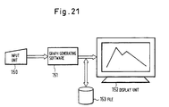
- a type of graph such as a graph of broken lines is designated by a packaged graph generating software from an input/output unti 150.
- a graph generating condition such as a type polygonal lines and object data for generating graph are input.
- a graph generating package software 151 edits athe graph in accordance with the generating condition input and object data in put for generating the graph.
- An edited graph displays a generated graph on the display unit 152 such as display.
- the generated graph is stored in a file 153 such as a flopply disk and such graph is then output to the display unit 152 as required.
- a required figure is generated by hand-writing method and the hand-written figure 160 is read with an image scanner and it is then input.
- the input figure data is processed in the image levl by a data processor 162 and the figure as the result has been output to a display unit 165 or X-Y plotter 166 owing to a display processor 164.
- the input digure data is stored in a figure file 163 and it can also be output to a display unit 165 or X-Y plotter 166 from the display processor 164 as required.
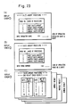
- the other terminal unit A is provided with a function to display the necessary display screens 1 , 2 , 3 for "daily sales amount”, “weekly sales amount”, “monthly sales amount” and “annual sales amount” for processing as shown in Figs. 23 (A), (B) and (C) and such function is used in the own terminal unit.
- terminal A is the other terminal unit, while the terminal B is the own terminal unit.
- reference numeral 170 denotes a network such as public network.
- the individual generating condition of the graph to be generated has been determined only for the generation program and it cannot be cnotrolled for common use in the other programs. Therefore, even when the graph to be generated is transferred to the other terminal units in the network system, it cannot ensure such applicability that another graph is generated by using only the numerical data as the object of graphic display or a figure of the same kind is generated by replacing a part of the graph generating condition with the other conditions and then changing and extending the graphs.
- a method of generating graph and figure in the terminal units of the present invention analyzes a kind of graph such as graph of polygonal lines and circular graph, a kine of line of graph, attribute of graph such as color, generating condition of figure and figure element by considering these as the parts to generate part codes and generates a figure by combining part codes in such a manner as, for example, executing the program processing through combination of the codes of the figure generating elements and figure generating conditions.
- classification such as graph of polygonal lines and bar graph is conducted based on the highest concept of generation of graph, and such classification is continued for minor items such as color and shape of bar graph next to the concept of the bar graph.
- the generating condition may also be decomposed to have flexibility from the point of view of analysis such as linking the designated coordinate positions with a solid line.
- the present invention generates the codes of such decomposed structural elements and generating condition as the part and registers such codes and combines such part codes indicating the processing function of the generating condition with the part codes of the structural elements and thereby gives the function as the commands in the program to generate the documents such as graphs and figures with combination of part codes and numerical data.
- the document generated as explained above includes less amount of data because it is generated through combination of part codes and such data may be easily extracted and used in the distant other terminal units. Moreover, since the document is generated based on the program through combination of the part codes, such document may flexibly edited and revised through alteration of part codes in regard to structural elements and generating conditions.
- the document may be used only between the codes coupled with a tree structure, but it may be used also between the part codes of the higher level concept in the present invention.
- the part codes developed in generation of graph may also be used for figure generating processing by applying the generating condition in the figure generation.
- the present invention enhances applicability of the document such as graph or figure generated by each terminal unit as the distributed data base in the network system.
- Fig. 1 is a basic structural diagram of the present invention.
- Fig. 2 is a diagram indicating a graph generating method in the network system of the present invention.
- Fig. 3 is a diagram indicating a figure generating method in the network system of the present invention.
- Fig. 4 is a diagram for indicating an embodiment of the figure generated.
- Fig. 5 is a diagram for indicating the network system of the present invention.
- Fig. 6 is a flowchart of display screen transfer processing in the network system of the present invention.
- Fig. 7 is a diagram for indicating an embodiment of display screen response processing in the network of the present invention.
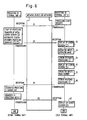
- Fig. 8 is a diagram for explaining a program download method in the network system of the present invention.
- Fig. 9 is a diagram for indicating a program download method in the network system of the present inventin.
- Fig. 10A is a digram for indicating an embodiment of conversation file in program download method.
- Fig. 11 is a diagram for indicating an embodiment flowchart of program download.
- Fig. 12 is a diagram for indicating an embodiment of the area control method in the network system of the present invention.
- Fig. 13 is a diagram for indicating a schedule control graph generating method in the network system of the present inventin.
- Fig. 14 is a diagram for indicating an embodiment flowchart (1) of a schedule control graph generating method.
- Fig. 15 is a diagram for indicating an embodiment flowchart of a schedule control graph generating method.
- Fig. 16 is a diagram for indicating a screen display method in the network system of the present invention.
- Fig. 17 is a digram for indicating a flowchart of page control in the screen display method of the present invention.
- Fig. 18 is a diagram for indicating a flowchart of continuous page feeding in the screen display method of the present invention.
- Fig. 19A is a diagram for indicating a flowchart of page control in the screen display method of the present invention.
- Fig. 19B is a diagram for indicating a flowchart of continuous display screen generating process in the screen display method of the present invention.
- Fig. 20 is a diagram for indicating a flowchart of page retrieval in the screen display method of the present invention.
- Fig. 21 is a diagram for indicating the graph generating method of the prior art.
- Fig. 22 is a diagram for indicating the figure generating method of the prior art.
- Fig. 23 is a diagram for indicating the displayed screen in the display screen data processing between terminal units of the prior art.
- Fig. 24 is a diagram for indicating a display screen data processing method between terminal units of the prior art.
- the reference numeral 1 denotes input unit 1 such as keyboard; 2, data input part for inputting the coded generating conditions such as coded program name and kind of graphs, etc.; 3, input data analyzing part for analayzing the codes of generating condition input, sharing messages for generation conditon input and object numerical data for graphic display and selecting program to be started.
- Numeral 4 denotes part file for registering coded processing functions corresponding to generating condition such as "coupling designated coordiantes with a solid line", structure element such as "block digram of logic circuit” and processing areas; 5, display screen file, which may also be used as a terminal output file, for storing display screen of figure or various menu screens; 6, program file for storing various programs; 7, figure pattern file having figure pattern data such as coded figure elements.
- Numeral 8 denotes development table for editing graphs and figures by developing the generating condition analyzed by the input data analyzing part 4 and selected program; 9, output processing part consisting of display output control part, print control part for providing print output to a printer, etc. and terminal output control part; 10, download program storing part for downloading program held in the other terminal unit in the network system to own terminal unit.
- Numeral 12 denotes display; 13, slip for providing printed output; 15, display output processing part providing a function to execute figure display processing and window display processing in order to display figure data on the display by referring to the figure data file based on the data of graph and figure edited by the development table; 16, print processing part; 17, terminal output processing part for outputting coded data generated to the other terminal units connected in the network system.
- Fig. 2 indicates a graph generating method in the network system of the present invention.
- numeral 20 denotes input unit; 21, data input part for inputting graph generating data; 23, part table storing coded graph generating condition (bar graph, etc.); 24, figure pattern file having pattern data for screen display for each coded attribute of graph such as color and kind of line of graphs; 25, program file having a plurality of graph generating program prepared for each type of graph; 26, graph figure pattern file retrieval part for retrieving figure pattern file 24 with the data such as coded graph attribute requested from the display output processing part and extracting relevant pattern data; 27, development table; 28, screen file for storing screen format or generated graph in the form of file which is prepared for each type of graph and is common to graphs; 29, display unit; 30, display output processing part for executing display output processing of graph data; 31, terminal output file for filing the graph generating data such as graph generating conditon in the form of code and object numerical data for graphic display.
- Fig. 2 the elements denoted by the same naming as those in Fig. 1 have the same function as that in Fig. 1 and the terminal output file in Fig. 2 is included to the screen file 5 in Fig. 1
- data input for geration of graphs is carried out by designating the position of cursor of the display position in the display screen of part codes or direct input of codes from the keyboard.
- the data such as name, object value data for graphic indication is input in accordance with the designation displayed on the screen.
- the coded graph generating condition includes type of graph such as polygonal line graph, circular graph and attribute of graph such as solid line, kind of line such as dotted line, and shading mode such as color, lattice and oblique lines.
- the coded graph generating condition is input to the data input part 21 and the condition type thereof is recognized in the input data analyzing part 22 by making reference to the part table 23.
- the input data analyzing part 22 shares the messages of graph generating data such as graph generating condition, name and object value data for graphic indication to respective condition types.
- the input data analyzing part 22 extracts the graph generating program corresponding to the type of graph to be generated from the program file 25 and then starts such program.
- the development table 27 fetches various data shared by the input data analyzing part 22 and also fetches the format of graph seed required from the display screen file 28.
- the development table 27 edits the graph in the form of code in accordance with graph generating data.
- the coded graph edited in the development table 27 is output to the display output processing part 30.
- the display output processing part 30 sends the coded graph attribute data to the figure pattern file retrieving part 11, the figure pattern file retrieving pat 26 retrieves a figure pattern file 24, extracts graph attribute pattern data required for graphic display and sends this pattern data to the display output processing part 30.
- the display output processing part 30 displays the graph on the display unit 29 based on the pattern data.
- the graph generating data edited by the development table 27 is registered to to the display screen file 28 or to the terminal output file 31 in the form of code.
- the terminal output file 25 outputs the generated graph to the other terminal units in accordance with the requests from the other terminal units.
- the graph generation data registered in the display screen file 25 or terminal output file 31 forms a document data in the form of program command through combination of generating condition code and structural elements. Therefore, such graph generating data may be processed and modified eaisly by changing the codes of generating condition and structural elements.
- Fig. 3 shows a figure generating system in the network of the present inventino.
- numeral 35 denotes input unit for inputting the figure generating conditions
- 36 data input part for inputting coded type of figure
- 37 input data analyzing part for analyzing input code and sharing messages
- 38 part code file registering coded structural elements of network diagram
- 39 figure pattern file storing, for example, pttern data of pattern of logic circuit block
- 40 program file having a plurality of figure generating program prepared for each type of figure
- 41 figure pattern file retrieving part for extracting pattern data of structural element of relevant figure by retrieving figure pattern file 39 with the coded structural element of figure requested from the display output processing part 45
- 42 development table
- 43 display screen file prepared for each type of figure to file data such as fomat which is common to the figures
- 44 display unit for displaying generated figure.
- 45 display output processing part for displaying figure data output from the development table 42
- 46 terminal output file for filing coded figure data generated in the development table 42.
- FIG. 3 the elements of the same name as those in Fig. 1 have the same function as those in Fig. 1.
- the terminal output file in Fig. 3 is included in the display screen file 5 in Fig. 1.
- data input for generation of figure is carrie dout by designation of cursor position at the display position in the display screen of part code or direct input of the code from the keyboard.
- the practical examples of structural elements and generating conditions for generating figure are as follow.
- the type of figure includes network diagram, shelf mounting diagram of printed circuit board, bay mounting diagram and the other figure generating condition includes name of figure, unit name, connecting condition between units, location of station, existence of backup line, name and pitch of printed circuit board, size of shelf and kind of shelf, etc.
- condition type of the coded structural elements and generating condition input to the data input part 36 is recognized in the input data analyzing part 37 by making reference to to the part code table 38 and the condition messsages are shared to the respective condition types.
- the input data analyzing part 37 extracts a figure generating program corresponding to type of figure to be generated afrom the program file 40 and then starts this program.
- the development table 42 fetches various data input from the data input part 36 and also fetches the required figure specifications from the display screen file 43. Moreover, the development table 42 edits the coded figure data in accordance with the figure data such as the figure generating condition including unit name, connecting condition between units shared by teh input data analyzing part 37 and coordinate data, etc.
- Coded figure data edited in the development table 42 is output to the display output processing part 45.
- the display output processing part 45 sends the codes of structural elements of the coded figure to the figure pattern file retrieving part 41 and this figure pattern file retrieving part 41 retrieves the figure pattern file 39, extracts pattern data of structural element of figure required for display of figure and then sends such pattern data to the display output processing part 45.
- the display output processing part 45 displays the generated figure on the display unit 44 based on the pattern data.
- the figure data edited by the development table 42 is registered in the form of code to the display screen file 43 or terminal output file 46.
- the terminal output file 46 is connected to the network and outputs the generated figure to the other terminal units.
- the graph generating data registered to the display screen file 43 or terminal output file 46 forms the document data in the form of program commands through coupling of the generating condition codeds and structural elements. Therefore, such graph generation data may be processed easily by changing the codes of generating conditions and structural elements in the other terminal units.
- Fig. 4 shows an embodiment of the generated figure which has been generated under the following conditions.
- reference numeral 51(PBX) denotes exchange (switching system); 52-1 52-3(VCOD), voice coder; 53 (DDIM), digital data control unit; 54(MD), modem.
- the network diagram as the type of figure and PBX, VCOD, DDIM, MD as the units are input in the form of codes registered in the parts file and are developed on the development table 42.
- the generated display screen data of network diagram is fetched to the development table by the codes corresponding to the network diagram from the display screen file 43.
- the numerical data which indicates the coordinate position on the display screen of each unit (for example, the start coordinate position 10-2 of figure pattern, in the case of PBX) is developed on the development table 42.
- the figure generating program is fetched from the program file 40 and the figure generating data is formed through coupling of incorporated codes and numerical data to form a figure as indicated in the figure on the development table.
- the figure pattern file retrieving part 41 retrieves the figure pattern file 39 based on the generating data, extracts pattern data of PBX parts in the form of codes and the display output processing part 45 displays the PBX pattern to the designated input position (10-2) in the registered pattern, for example, for PBX on the basis of the edited data.
- the figure elements (PBX, VCOD, etc.) are connected with a solid line in accordance with the definition "connected with a solid line from the center of the side surface of units" which is previously defined as “usual” under the generating condition input and thereby the network diagram as indicated in the figure is displayed on the screen.
- Fig. 5 is a structural diagram of the network system to which the present invention is applied.
- the network system of the present invention provides a control center 56 and employs a structure that a plurality of terminal units A, B, C,.... are connected in the network 55.
- the graph generated by the method of the present invention is used from the other terminal units connected in the network 55.
- the document such as figure and program is coded for flexible use in the network system. Therefore, it is possible to easily fetch the generated figures and programs in the other terminal units to the self terminal unit for use.
- Fig. 6 is a flowchart of the display screen transfer processing in the network system of the present invention and Fig. 7 indicates an embodiment of the display screen response processing of the transferred display screen.
- the program of the other terminal unit is read in the self terminal unit (program download) and is executed in the self terminal unit.
- Fig. 8 is a diagram for explaining the program download method in the network system of the present invention.
- numeral 65 denotes operator; 66, display unit; 67, self terminal unit; 68 , conversation sensor program for realizing a series of procedures including decision of program to be started and setting of parameters between the operator and self terminal unit in the form of conversation and for realizing access to the other terminal units; 69 , conversation file for storing conversation information and attribute information; 70 , program file; 71, 71', files in the conversation file for describing conversation information and attribute information required for making conversation with an operator 65 to each processing file; 72, 72', download describing columns for description of "necessity" to realize program download in the self terminal unit 67 and execute the processing of file name (program name) thereof or "unnecessity" to realize execution in the other terminal unit.
- file name program name
- download decision program for deciding "necessity” or “unnecessity” described in the download describing columns 72, 72'
- transfer request program for requesting transfer of the processing program to execute the processing of file name in the self terminal unit when "necessity" is described in the downlowd describing column 72
- download program storing part for storing the processing program sent from the other terminal units by the execution of such transfer request program.
- 80 operator; 81, display; 82, self terminal unit; 83, other terminal unit; 84 , conversation sensor program; 85, download program; 86, transfer request program; 87, conversation file; 88, download program storing part; 89, public line network; 90, memory in the terminal unit 83; 90', program stored in the memory 90; 91, download control part for reading the requested program 90' from the memory 91 and transfers the program to the other terminal unit (the self terminal unit 82, in this case) when the other temrinal unit (the self terminal unit 82, in this case) requests transfer of program.
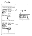
- Fig. 10A is an embodiment of the conversation file.
- the files 92, 93 are provided with the column for describing necessity or unnecessity of program download as the attribute information.
- “necessity” is described in this column and when the program download is impossible and processing is executed in the terminal unit comprising the processing program, "unnecessity” is described. Description of “necessity” and “unnecessity” is previously decided at the stage of design, based on the experience considering necessity of conversaton with the other system.
- Fig. 10B indicates an embodiment of the screen display in the converdation processing of program download.
- the conversation information for the file 92 "calculation processing 1" is displayed on the display unit.
- the self terminal unit recognizes the terminal unit storing such program and the public line network and issues the program transfer request to such terminal unit.
- Fig. 11 is a flowchart of an embodiment of program download of the present invention.
- the file "calculation processing 1" (program name: "keisan-prol") has been explained but the other files are also processed in the same way. Namely, it is decided whether the self terminal unit 82 executes the object program in the self terminal unit after download of program or the other terminal unit executes such object program, depending on "necessity” or “unnecessity” of download described previously in the download describing column of the file as the attribute information.
- the download program method of the present invention since the program, which requires frequent communication with the self terminal unit through the public line network during execution while it exists in the other terminal unit, is automatically downloaded to the self terminal unit, the line application efficiency of the network system can be improved.
- duch data may be easily transferred or used between distant terminal units.
- the area for storing data is defined when the data is generated and is coded.
- the defined area is used as the command and the coupling between the desired processing functions is designated by the parts code table and thereby the contents of area may be set, altered or added freely.
- Fig. 12 is an embodiment of the area control method in the network system of the present invention.
- the area for storing data is defined, such defined area is used as the command, coupling between such command and desired processing function is designated by the parts file and such command is allowed to be used in the other processing function, thereby the processing contents for such area may be freely set, altered or added.
- Fig. 12 is an embodiment in case the area control method explained above is applied to the arithmetic operation processing.
- numeral 111 denotes parts code file to which the area name of the area for storing data generated in accordance with the arithmetic calculation formula to be processed and the command (code) for designating the processing function to be applied to such area are registered as the parts.
- S1, S2 and S3 indicate the area names of defined areas. For instance, such area names are formed as the commands (codes) indicating the addition processing program.
- 112 denotes address assignment table, indicating the real addresses of areas indicated by S1, S2, S3, X indicating commands and area names on the parts table.
- 113 denotes real data file for storing data such as numerical values; 114, arithmetic operation development program for calling a function program to be processed for the area (S1, S2, etc.) designated by the area name; 115, development table for developing area name (S1, S2, etc.), real data on the area designated by the area nameand information for calling the program to be applied to the area developed; 116, 117, arithmetic operation program listed as the example and called on the development table in accordance with instruction of the arithmetic operation development program developed on the devlopment table.
- the area name "expenses for clothing” is registered to the defined area S1 on the parts code file, while “expenses for foods” to the area S2, “expenses for lighting and fuel” to the area S3 and "Total" to the area X.
- S1, S2, S3 correspond, for example, to the positon of table on the display screen in the table calculation processing.
- the addresses of defined area are assingend by the address assignment table 112. Moreover, respective real data are stored in the defined areas S1, S2, S3 on the real data file.
- the atithmetic operation development program develops, with the commands of S1, S2, S3, the real address on each domain and the information for calling the program to be processed.
- the "+" program defined in S1, S2, S3 is called, the arithmetic operations S1 + S2, (S1 + S2) + S3 are executed for the real data on the regions S1, S2, S3 in accordance with the commands (S1, S2, S3, X, etc.) and the result data is stored in the region X.
- the other processing function is applied, when necessary, to the data in the domain X.
- the function to be effectuated on the defined domains S1, S2, etc. may be applied not only to the elements of arithmetic operation processing program but also to the generation and display of display screen data, generation of fixed data of display screen, control (grouping) of data link in the form of table, graphic display of data and generation of figure of data and these functions may be realized by the corresponding processing programs.
- Fig. 13 indicates a schedule table generating method, while (b), display screen of the graphic display of generated schedule.
- numeral 120 denotes a new schedule buffer allowing entry of schedule bit 1 to the scheduled time and schedule bit 0 to the not scheduled time to store the newly generated schedules; 121, old schedule buffer storing already determined schedule data.
- schedule control part for controlling the schedules based on the new schedule buffer 120 and old schedule buffer 121; 123, updated schedule buffer for obtaining OR of the new schedule buffer 120 and old schedule buffer 121; 124, OR circuit for obtaining OR of the new schedule buffer 120 and old schedule buffer 121.
- schedule table setting the start position and duration (length) of the graphic display for indicating the schedules with a graph based on the schedule bits of the updated schedule buffer 123 and also providing the names of schedules.
- the time of the display start position 0 is set to 9 o'clock.
- Fig. 13 (b) indicates a display screen of the schedule control graph generated on the basis of the schedule table 125.
- the time corresponding to the display start positon 0 is set to 9 o'clock and display start position, duration of schedule table and names of schedules are displayed as the graph.
- Fig. 14 shows flowchart (1) of the schedule control graph generating method in the network system of the present invention.
- 126 denotes flow in the schedule control part
- 127 flowchart in the display part for showing the updated schedule in the form of graph and displaying such graph.
- Fig. 15 indicates flow (2) as the embodiment of the display part in the schedule control graph generating method. Only the flow of display part is indicated and the flow in the schedule control part is the same as Fig. 14.
- the schedule table 125 shown in Fig. 13 displays a graph by extacting only the name but it is also possible to obtain the graph using the graph generating method shown in Fig. 2 based on the display start position, duration and name stored in the schedule table 125.
- the terminal units in the network system of the present invention form a single display screen as the gathering of coded parts data and easily fetch the data of the other display screens.
- the window control for introducing the screen number into the display data of display screen file can be realized easily and the continuous screen processing in the multi-window can also be realized easily by fetching a plurality of display screens.
- the screen display method in the network system of the present invention is shown in Fig. 16.
- 130 denotes display unit; 131, window controller; 132, development table; 133, display screen file for controlling generated figures and generated graphs in accordance with the numbering of registeration; 134, continuous page processing part; 135, page controller; 136, display screen selecting process; 137, pointing device such as mouth; 138, continuous display screen generation procesing part; 139, page retrieval processing part; 140, the display screen number replacing edition processing part; 141, screen display request from operator. operations of structure shown in the figure are explained in accordance with the numbering in the circles.
- Fig. 17 shows a flow of page control in the screen display method of the present invention.
- Fig. 18 is a flow of continuous page cutting process in the screen display method of the present inventin.
- step 3 If the continuous processings are not started in the step 3 , the processing is terminated. When it is decided that all screens are displayed in the step 8 , the processing is terminated.
- Fig. 19A shows a flow of page control in the screen display method of the present invention.
- Fig. 19B shows a flow of continuous display screen generating process in the screen display method of the present invention.
- Fig. 20 shows a flow of page retrieval in the screen display method of the present invention.
- the present invention prepares the coded structural elements and generating conditions of documents to be generated as the independent parts and forms a document by giving the function like commands of organic programs to each independent part through combination of parts.
- the present invention easily and flexibly processes and alters the generated documents by changing the parts codes used in the document generation.
- the document data is formed with the code format, amount of data can be decreased and data may also be used even in the distant other terminal units through the transfer of data.
- the present invention remarkably enhances applicability of network system by registering the documents generated in each terminal unit to the file of termnal unit as the distributed data base and then utilizing such documents in the other terminal units.
Landscapes
- Physics & Mathematics (AREA)
- General Physics & Mathematics (AREA)
- Engineering & Computer Science (AREA)
- Theoretical Computer Science (AREA)
- Information Transfer Between Computers (AREA)
- Computer And Data Communications (AREA)
Abstract
Procédé de préparation de documents dans un système en réseau, visant à permettre l'utilisation mutuelle de documents entre les terminaux. A cet effet, les terminaux disposent d'un fichier composants (4) dans lequel sont enregistrés les éléments codés d'un document et les conditions codées de préparation de ce document, d'un fichier programme (6) comprenant un programme permettant de préparer différents documents, et d'une table d'extension (8), permettant d'étendre les conditions de préparation codées, les éléments et les programmes. Les codes d'éléments servant à préparer les documents et les codes de conditions de préparation sont étendus dans la table d'extension (8), et les documents sont préparés grâce à la combinaison des codes d'éléments et des codes de conditions de préparation.
Applications Claiming Priority (12)
| Application Number | Priority Date | Filing Date | Title |
|---|---|---|---|
| JP23605289 | 1989-09-12 | ||
| JP236053/89 | 1989-09-12 | ||
| JP236052/89 | 1989-09-12 | ||
| JP23605389 | 1989-09-12 | ||
| JP270048/89 | 1989-10-17 | ||
| JP27004889 | 1989-10-17 | ||
| JP297961/89 | 1989-11-16 | ||
| JP29796189 | 1989-11-16 | ||
| JP339370/89 | 1989-12-27 | ||
| JP33937089 | 1989-12-27 | ||
| JP9983090 | 1990-04-16 | ||
| JP99830/90 | 1990-04-16 |
Publications (2)
| Publication Number | Publication Date |
|---|---|
| EP0451282A1 true EP0451282A1 (fr) | 1991-10-16 |
| EP0451282A4 EP0451282A4 (en) | 1993-02-03 |
Family
ID=27552082
Family Applications (1)
| Application Number | Title | Priority Date | Filing Date |
|---|---|---|---|
| EP19900913533 Withdrawn EP0451282A4 (en) | 1989-09-12 | 1990-09-12 | Network system consisting of terminals having document preparing function |
Country Status (3)
| Country | Link |
|---|---|
| EP (1) | EP0451282A4 (fr) |
| CA (1) | CA2041663A1 (fr) |
| WO (1) | WO1991004545A1 (fr) |
Families Citing this family (1)
| Publication number | Priority date | Publication date | Assignee | Title |
|---|---|---|---|---|
| US6678864B1 (en) * | 1992-02-25 | 2004-01-13 | Irving Tsai | Method and apparatus for linking designated portions of a received document image with an electronic address |
Family Cites Families (8)
| Publication number | Priority date | Publication date | Assignee | Title |
|---|---|---|---|---|
| JPS5992654A (ja) * | 1982-11-09 | 1984-05-28 | インタ−ナショナル ビジネス マシ−ンズ コ−ポレ−ション | 電子文書配送システム |
| JPS62211769A (ja) * | 1986-03-12 | 1987-09-17 | Fujitsu Ltd | コンピユ−タネツトワ−クシステム |
| JPS6336387A (ja) * | 1986-07-30 | 1988-02-17 | Nec Corp | グラフ表示方式 |
| JPS63129481A (ja) * | 1986-11-20 | 1988-06-01 | Toshiba Corp | グラフ表示装置 |
| US4932026A (en) * | 1986-12-19 | 1990-06-05 | Wang Laboratories, Inc. | Apparatus for distributing data processing across a plurality of loci of control |
| JPS63292257A (ja) * | 1987-05-11 | 1988-11-29 | インタ−ナショナル・ビジネス・マシ−ンズ・コ−ポレ−ション | 複数の端末局へのデ−タまたはプログラムのロ−デイング方法 |
| JPS63280369A (ja) * | 1987-05-13 | 1988-11-17 | Mitsubishi Electric Corp | オンライン計算機ネットワ−ク装置 |
| FR2624632A1 (fr) * | 1987-12-14 | 1989-06-16 | Guillot Pierre | Procede d'archivage automatique de documents sur unite de stockage utilisant une transmission compactee et cryptee, et le serveur documentaire pour sa mise en oeuvre |
-
1990
- 1990-09-12 CA CA002041663A patent/CA2041663A1/fr not_active Abandoned
- 1990-09-12 EP EP19900913533 patent/EP0451282A4/en not_active Withdrawn
- 1990-09-12 WO PCT/JP1990/001169 patent/WO1991004545A1/fr not_active Ceased
Also Published As
| Publication number | Publication date |
|---|---|
| EP0451282A4 (en) | 1993-02-03 |
| WO1991004545A1 (fr) | 1991-03-21 |
| CA2041663A1 (fr) | 1991-03-13 |
Similar Documents
| Publication | Publication Date | Title |
|---|---|---|
| US5448375A (en) | Method and system for labeling a document for storage, manipulation, and retrieval | |
| US5502839A (en) | Object-oriented software architecture supporting input/output device independence | |
| US5062060A (en) | Computer human interface comprising user-adjustable window for displaying or printing information | |
| US5003499A (en) | Document preparation apparatus having rearrangement apparatus for rearranging text according to region attribate information | |
| JPH0616274B2 (ja) | データ・ストリーム作成方法 | |
| WO1999007007A2 (fr) | Systeme informatise et procede associe pour le controle optimal de la mise en memoire et du transfert de programmes informatiques sur reseau informatique | |
| EP0829801A2 (fr) | Procédé d'affichage d'objets fonctionnels dans un environnement de programmation visuelle | |
| US20070291026A1 (en) | Method and device for preparing a parts catalog | |
| CN115061980B (zh) | Dwg同一画布中多张图纸转换为多页pdf图纸的方法 | |
| EP0451282A1 (fr) | Systeme en reseau compose de terminaux possedant une fonction de preparation de documents | |
| EP0274087A2 (fr) | Interface homme-machine | |
| JPH05165933A (ja) | 図形処理システム | |
| JPH1188592A (ja) | 画像送受信装置および画像データの加工・編集プログラムを記録した記録媒体 | |
| JPH04223552A (ja) | ミクストモード文書作成装置 | |
| JPH1011271A (ja) | バージョンダウン入力方式 | |
| JPH0991189A (ja) | 画像通信装置及び方法 | |
| JP3136852B2 (ja) | タッチパネル画面作成方法およびその装置 | |
| JPH1031752A (ja) | 図面入力装置の認識結果修正装置 | |
| JP3021347U (ja) | 制御系キャド装置 | |
| JPH0991188A (ja) | 画像通信装置及び方法 | |
| JPWO1991004545A1 (ja) | 文書作成機能を備える端末装置よりなるネットワークシステム | |
| JP4438625B2 (ja) | 表示装置 | |
| JP2005338404A (ja) | チラシ流用商品指定システム、チラシ流用商品指定方法 | |
| EP0637811A2 (fr) | Procédé pour définir plusieurs jeux de données de définition de formulaire | |
| JPH064199A (ja) | キーパターン作成方法及び装置 |
Legal Events
| Date | Code | Title | Description |
|---|---|---|---|
| PUAI | Public reference made under article 153(3) epc to a published international application that has entered the european phase |
Free format text: ORIGINAL CODE: 0009012 |
|
| 17P | Request for examination filed |
Effective date: 19910508 |
|
| AK | Designated contracting states |
Kind code of ref document: A1 Designated state(s): DE FR GB |
|
| A4 | Supplementary search report drawn up and despatched | ||
| AK | Designated contracting states |
Kind code of ref document: A4 Designated state(s): DE FR GB |
|
| 17Q | First examination report despatched |
Effective date: 19950808 |
|
| STAA | Information on the status of an ep patent application or granted ep patent |
Free format text: STATUS: THE APPLICATION IS DEEMED TO BE WITHDRAWN |
|
| 18D | Application deemed to be withdrawn |
Effective date: 19990302 |