EP0451783B1 - Dispositif de commande de l'air d'admission de chaque cylindre d'un moteur à combustion interne et méthode pour commander cette quantité d'air avec des caractéristiques améliorées - Google Patents
Dispositif de commande de l'air d'admission de chaque cylindre d'un moteur à combustion interne et méthode pour commander cette quantité d'air avec des caractéristiques améliorées Download PDFInfo
- Publication number
- EP0451783B1 EP0451783B1 EP91105602A EP91105602A EP0451783B1 EP 0451783 B1 EP0451783 B1 EP 0451783B1 EP 91105602 A EP91105602 A EP 91105602A EP 91105602 A EP91105602 A EP 91105602A EP 0451783 B1 EP0451783 B1 EP 0451783B1
- Authority
- EP
- European Patent Office
- Prior art keywords
- intake air
- engine
- opening angle
- bypass
- throttle valves
- Prior art date
- Legal status (The legal status is an assumption and is not a legal conclusion. Google has not performed a legal analysis and makes no representation as to the accuracy of the status listed.)
- Expired - Lifetime
Links
Images



Classifications
-
- F—MECHANICAL ENGINEERING; LIGHTING; HEATING; WEAPONS; BLASTING
- F02—COMBUSTION ENGINES; HOT-GAS OR COMBUSTION-PRODUCT ENGINE PLANTS
- F02D—CONTROLLING COMBUSTION ENGINES
- F02D41/00—Electrical control of supply of combustible mixture or its constituents
- F02D41/0002—Controlling intake air
-
- F—MECHANICAL ENGINEERING; LIGHTING; HEATING; WEAPONS; BLASTING
- F02—COMBUSTION ENGINES; HOT-GAS OR COMBUSTION-PRODUCT ENGINE PLANTS
- F02D—CONTROLLING COMBUSTION ENGINES
- F02D11/00—Arrangements for, or adaptations to, non-automatic engine control initiation means, e.g. operator initiated
- F02D11/06—Arrangements for, or adaptations to, non-automatic engine control initiation means, e.g. operator initiated characterised by non-mechanical control linkages, e.g. fluid control linkages or by control linkages with power drive or assistance
- F02D11/10—Arrangements for, or adaptations to, non-automatic engine control initiation means, e.g. operator initiated characterised by non-mechanical control linkages, e.g. fluid control linkages or by control linkages with power drive or assistance of the electric type
-
- F—MECHANICAL ENGINEERING; LIGHTING; HEATING; WEAPONS; BLASTING
- F02—COMBUSTION ENGINES; HOT-GAS OR COMBUSTION-PRODUCT ENGINE PLANTS
- F02D—CONTROLLING COMBUSTION ENGINES
- F02D41/00—Electrical control of supply of combustible mixture or its constituents
- F02D41/24—Electrical control of supply of combustible mixture or its constituents characterised by the use of digital means
- F02D41/26—Electrical control of supply of combustible mixture or its constituents characterised by the use of digital means using computer, e.g. microprocessor
- F02D41/266—Electrical control of supply of combustible mixture or its constituents characterised by the use of digital means using computer, e.g. microprocessor the computer being backed-up or assisted by another circuit, e.g. analogue
-
- F—MECHANICAL ENGINEERING; LIGHTING; HEATING; WEAPONS; BLASTING
- F02—COMBUSTION ENGINES; HOT-GAS OR COMBUSTION-PRODUCT ENGINE PLANTS
- F02D—CONTROLLING COMBUSTION ENGINES
- F02D43/00—Conjoint electrical control of two or more functions, e.g. ignition, fuel-air mixture, recirculation, supercharging or exhaust-gas treatment
-
- F—MECHANICAL ENGINEERING; LIGHTING; HEATING; WEAPONS; BLASTING
- F02—COMBUSTION ENGINES; HOT-GAS OR COMBUSTION-PRODUCT ENGINE PLANTS
- F02D—CONTROLLING COMBUSTION ENGINES
- F02D11/00—Arrangements for, or adaptations to, non-automatic engine control initiation means, e.g. operator initiated
- F02D11/06—Arrangements for, or adaptations to, non-automatic engine control initiation means, e.g. operator initiated characterised by non-mechanical control linkages, e.g. fluid control linkages or by control linkages with power drive or assistance
- F02D11/10—Arrangements for, or adaptations to, non-automatic engine control initiation means, e.g. operator initiated characterised by non-mechanical control linkages, e.g. fluid control linkages or by control linkages with power drive or assistance of the electric type
- F02D2011/101—Arrangements for, or adaptations to, non-automatic engine control initiation means, e.g. operator initiated characterised by non-mechanical control linkages, e.g. fluid control linkages or by control linkages with power drive or assistance of the electric type characterised by the means for actuating the throttles
- F02D2011/102—Arrangements for, or adaptations to, non-automatic engine control initiation means, e.g. operator initiated characterised by non-mechanical control linkages, e.g. fluid control linkages or by control linkages with power drive or assistance of the electric type characterised by the means for actuating the throttles at least one throttle being moved only by an electric actuator
-
- Y—GENERAL TAGGING OF NEW TECHNOLOGICAL DEVELOPMENTS; GENERAL TAGGING OF CROSS-SECTIONAL TECHNOLOGIES SPANNING OVER SEVERAL SECTIONS OF THE IPC; TECHNICAL SUBJECTS COVERED BY FORMER USPC CROSS-REFERENCE ART COLLECTIONS [XRACs] AND DIGESTS
- Y02—TECHNOLOGIES OR APPLICATIONS FOR MITIGATION OR ADAPTATION AGAINST CLIMATE CHANGE
- Y02T—CLIMATE CHANGE MITIGATION TECHNOLOGIES RELATED TO TRANSPORTATION
- Y02T10/00—Road transport of goods or passengers
- Y02T10/10—Internal combustion engine [ICE] based vehicles
- Y02T10/40—Engine management systems
Definitions
- the present invention relates to an apparatus for controllably sucking intake air into each cylinder of an internal combustion engine and method for controlling intake air quantity of the internal combustion engine with improved responsive characteristic.
- traction control system (TCS) which is provided with an auxiliary throttle valve installed within a throttle chamber of an intake air passage of a vehicular engine in series with a first throttle valve (installed within the throttle chamber) associated with an accelerator pedal, the auxiliary throttle valve being driven by means of a electric motor which pivots the auxiliary throttle valve in response to a control signal.
- TCS traction control system
- the traction control system further includes a first sensor for detecting a rotational speed of each driven tire wheel of the vehicle, a second sensor for detecting a rotational speed of each non-driven (steered) tire wheel, and calculation means for calculating a difference between both rotational speeds of the driven and non-driven wheels to monitor a slip condition. Then, the traction control system controls an opening angle of the auxiliary throttle valve toward a closed position when the slip condition appears so that the engine output is reduced, an excessive intake air quantity caused by the instantaneous opening angle of the first throttle valve being throttled by means of the auxiliary throttle valve.
- Such a traction control system as desribed above is exemplified by United States Patents No. 4, 850,659, No. 4, 811, 808, No. 4, 765, 430, and No. 4, 969, 102.
- a surge i.e., a low frequency vibration of a vehicle body in forward and rearward directions during a cruise run or during a vehicle acceleration/deceleration due to an unsmooth operation of the vehicular engine, is easy to occur.
- the auxiliary throttle valve can be used to control the engine output, irrespective of the opening angle of the first throttle valve controlled in association with the accelerator pedal operation, such that the engine output is once reduced during a gear shift (for example, gear range up-shift from a third gear range to a fourth gear range) of a gear range of a vehicular power transmission accociated with the engine in order to reduce or relieve a shock occurred during the gear shift operation, the responsive characteristic of the engine output to the controlled opening angle control of the auxiliary throttle valve is worse. It is desirable and necessary to improve such a worse responsive characteristic if such an engine output control system is put into practice.
- the intake air supplied via the bypass passage is once filled in the intake manifold collector portion and, then, sucked into the engine.
- the response delay also occurs in the case of the idling speed control through the idling speed control valve in the same way as the response delay in the engine output control through the auxiliary throttle valve due to the presence of the collector capacity.
- the US-A-4,753,200 teaches an engine combustion control system.
- an arrangement serves to swirl airflow into an engine in an adjustable degree.
- the degree of swirl in the airflow affects the duration of combustion of the mixture of air and fuel in the engine.
- the degree of swirl is adjusted to keep the duration of mixture combustion within an acceptable range.
- the DE-A-3631474 discloses a suction system for an internal combustion engine comprising a first valve assembly for opening and closing a suction duct leading to each combustion chamber.
- a bypass channel for providing suction air into each combustion chamber bypasses the first valve assembly and comprises a second valve assembly for opening and closing each bypass channel.
- the intake air sucking apparatus can improve the responsive characteristic of a surge absorption control, traction control, feedback control of the engine idling speed, and gear shift shock reduction control.
- Fig. 1 is a schematic circuit block diagram of an apparatus for sucking an intake air into each engine cylinder of an internal combustion engine associated with a vehicular power transmission in a preferred embodiment according to the present invention.
- Fig. 2 is a first operational flowchart executed by an engine control unit of the intake air sucking apparatus shown in Fig. 1.
- Figs. 3 (A) and 3 (B) are integrally a second operational flowchart executed by the engine control unit of the intake air sucking apparatus shown in Fig. 1.
- Fig. 4 is a third operational flowchart executed by an automatic transmission control unit of the intake air sucking apparatus shown in Fig. 1.
- Fig. 5 is a fourth operational flowchart executed by the engine control unit of the intake air sucking apparatus shown in Fig. 1.
- Fig. 6 is a fifth operational flowchart executed by the engine control unit of the intake air sucking apparatus shown in Fig. 1.
- Fig. 1 shows a preferred embodiment of an apparatus for sucking intake air into each engine cylinder of an internal combustion engine associated with an automatic power transmission according to the present invention.
- the internal combustion engine 1 is a four-cylinder, four-stroke engine. Intake air is sucked through an air cleaner 2, throttle chamber 3, and intake manifold 4 into a combustion chamber of each engine cylinder. Exhaust gas emitted from each combustion chamber is passed through an exhaust manifold 5.
- a first throttle valve 7 is installed within the throttle chamber 3, the first throttle valve 7 being of a butterfly type whose opening angle is controlled according to a depression force on an accelerator pedal 6 of a vehicle.
- a first throttle sensor 8 constituted by a potentiometer detects an opening angle TV01 of the first throttle valve 7.
- An airflow meter 9 for detecting an intake air quantity Q of the engine is installed at an upper stream portion of the first throttle valve 7.
- a plurality of second throttle valves 11a through 11d of butterfly types are installed in intake ports 4a through 4d branched from the intake manifold 4.
- the second throttle valves 11a through 11d are provided with an integral throttle shaft 10 on which the butterfly second throttle valves 11a through 11d are pivoted by means of a servo motor 12.
- the servo motor 12 acting as an actuator is provided to actuate the second throttle valves 11a through 11d through the throttle shaft 10 to pivot the second throttle valves 11a through 11d through a given angle. It is noted that one end of the throttle shaft 10 opposing the servo motor 12 is provided with a second throttle sensor 13 constituted by another potentiometer for detecting an opening angle TV02 of the second throttle valves 11a through 11d.
- the servo motor 12 is provided with a spring mechanism which biases the second throttle valves 11a through 11d toward a completely open direction. When the servo motor 12 fails, the spring mechanism acts to open the second throttle valves 11a through 11d to provide a failsafe structure for the first throttle valve 7.
- a bypass passage 14 is branched from an upper stream of the first throttle valve 7.
- the bypass passage 14 is, then, branched into four bypass passages 14a through 14d at the respective downstream portions of the intake ports 4a through 4d.
- the bypass passage 14 serves to bypass the first throttle valve 7 and second throttle valves 11a through 11d to directly introduce the atmospheric air into the respective engine cylinders.
- an open position and open direction of the respective intake ports are set so that the air introduced from the bypass passages 14a through 14d into the intake ports 4a through 4d is supplied to the respective combustion chambers in a form of swirl stream.
- Electromagnetic fuel injection valves 15a through 15d are installed on predetermined positions of the intake ports 4a through 4d adjacient to exits of the respective bypass passages 14a through 14d.
- An electromagnetic bypass airflow quantity control valve 16 which controls the bypass airflow quantity in the bypass passge 14 according to a duty ratio of the input control signal is installed on a position before (upstream of ) the branched bypass passages 14a through 14d.
- the intake air supplied via the respective intake ports 4a through 4d and via the bypass passages 14a through 14d is introduced into the respective combustion chambers via the intake valves 17 (in this embodiment, two intake valves are installed).
- the exhaust gas emitted through two exhaust valves 18 of each cylinder is exhausted to an exhaust manifold 5.
- An integrated passage of the exhaust manifold 5 is provided with an oxygen sensor 19 for detecting an air/fuel mixture ratio of air fuel mixture supplied to the engine from an oxygen concentration of the exhaust gas.
- the detected signal of the oxygen sensor 19 is supplied to an engine control unit (ENG. C/U) 23 so that the actual air/fuel mixture ratio is fedback controlled to coincide with a target air/fuel mixture ratio (stoichiometric air/fuel mixture ratio).
- a camshaft associated with an engine crankshaft (not shown) is provided with a cam sensor 20 for detecting an engine crankshaft rotational angle.
- the cam shaft sensor 20 outputs a reference angle signal REF whenever each piston of the cylinders reaches a top dead center (TDC).
- an electromagnetic valve 22 is installed in an accelerator drum 21 to open the first throttle valve 22 through a predetermined angle with no depression force imposed on an accelerator pedal 6 when it is energized.
- the engine control unit 23 executes controls over the servo motor 12, bypass intake air quantity control valve 16, fuel injection valves 15a through 15d. and electormagnetic valve 22.
- the control unit 23 receives the detected signals derived from the first throttle sensor 8, airflow meter 9, second throttle sensor 13, oxygen sensor 19, cam sensor 20, and so forth.
- a front wheel rotational speed sensor 24 is installed for detecting a rotational speed of a front wheel and a rear wheel (driven wheel) rotational speed sensor 25 is installed for detecting a rotational speed of a rear wheel.
- the control unit 23 receives the detected signals derived from the respective rotational speed sensors 24 and 25.
- front wheel and rear wheel rotational speed sensors 24, 25 are exemplified by a United States Patet No. 4, 866, 623 issued on September 12, 1989 (a disclosure of which is herein incorporated by reference).
- An output axle of the engine 1 is connected to an automatic transmission (A/T) 26 via a torque converter.
- the automatic transmission is provided with a self-contained control unit 27.
- the control unit 27 receives the detected signal derived from the rear wheel rotational speed sensor 25 to detect the vehicle speed, a gear speed range select signal derived from an inhibitor switch installed on a select lever (not shown), and the detected signal of an operating variable of accelerator pedal 6 derived from an acceleration sensor 30.
- control unit 23 for the engine and that 27 for the automatic transmission (A/T) are mutually communicable.
- Each control unit 23 and 27 is generally constituted by a CPU, ROM, RAM, and I/O interface.
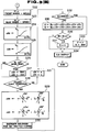
- Figs. 2 to 6 show program flowcharts for explaining operation in the intake air sucking apparatus in the preferred embodiment according to the present invention.
- Fig. 2 is a first program flowchart executed by the control unit 23 which is started in response to the output of the reference angle signal REF from the cam sensor 20 whenever each piston of the cylinders reaches the top dead center (TDC).
- a TDC period derived as an output interval from a previously derived reference angle signal REF to a currently derived reference angle signal REF is stored on a time series basis.
- the latestly measured TDC period is set to T0 and the TDC period set as T0 during the previous execution of the program of Fig. 2 is set to T1 as one previous data.
- the previously derived TDC period data T1, T2, and T3 are respectively set to T2, T3, and T4 as one previous data.
- the TDC period from the latest TDC period to the oldest TDC period i.e., before TDC periods of four previous times (before engine two revolutions) is set.
- a determination value LU indicating a magnitude of irregular driving condition is calculated using the above-described TDC period in accordance with the following equation: LU ⁇ T2 - T4 - T0 - T2 T4 3 or T2 3 or T0 3
- a numerator indicates a two-order differential value of the TDC period T (engine revolutional speed) and is calculated to be approximately zero provided that an acceleration in a change of the period T is constant.
- the numerator indicates a plus value when the acceleration of the vehicle body is increased and a minus value when the acceleration thereof is decreased.
- the engine output is controlled so as to suppress variations of the value of (T2 - T4) - (T0 - T2) with a zero as a center, the vehicle acceleration ( a first-order differential value of the TDC period) of the period T (engine revolutional speed) can be maintained constant.
- the engine intake air quantity can be controlled on the basis of the determination value LU as will be described later.
- the determination value LU is correlated to a variation in a mean effective pressure between each cylinder.
- Control can be simplified since it is not necessary to variably set the controlled variable for each driving condition.
- a program flowchart shown in Figs. 3 (A) and 3 (B) is executed by the control unit 23 whenever a predetermined period of time is elapsed.
- a step S11 the determination value LU calculated in the program flowchart shown in Fig. 2 is passed through a software band-pass filter to take out a component having a predetermined frequency range (.e.g., 1 to 10 Hz), in the frequency range of which a vehicular occupant perceives the surge.
- the component is set as LUf.
- a correction coefficient ⁇ S1 of the opening angle of the second throttle valves 11a through 11d to absorb the surge is searched from a map on the basis of the value of LUf set in the step S11.
- a correction coefficient ⁇ Z1 of the opening angle of the bypass intake air quantity control valve 16 is searched from a map on the basis of the value of LUf set in the step S11.
- both of the correction coefficients ⁇ S1 and ⁇ Z1 are set to indicate minus (plus) values when the value of LUf indicates a plus (minus) value.
- the intake air quantity is correctively controlled so that the acceleration of the engine revolutional speed is fixed to be constant and the surge is absorbed. That is to say, when the acceleration of the engine revolutional speed is changed at the frequency perceived by the vehicular occupant, the opening angles of the second throttle valves 11a through 11d and of the bypass intake air flow control valve 16 are controlled independently of the first throttle valve 7.
- a step S14 the CPU of the control unit 23 sets the opening angle TV01 of the first throttle valve 7 detected by the first throttle sensor 8.
- a step S15 the opening angle TV02 of the second throttle valves 14a through 14d is set detected by the second throttle sensor 13.
- a step S16 the CPU of the control unit 23 converts the opening angle TV01 of the first throttle valve 7 set in the step S14 into an opening area (m 2 ) of the throttle chamber 3 by searching a map.
- the derived opening area is set as A1 and M1, respectively. M1 will be described later.
- a step S17 the opening angle TV02 of the second throttle valves 11a through 11d set in the step S15 is converted into an opening area (m 2 ) of each intake air port 4a through 4d.
- the opening area is set as A2 and M2.
- a basic opening angle S0 of the second throttle valves 11a through 11d is set by searching a map on the basis of the opening area A1 of the first throttle valve 7 derived in the step S17.
- the basic opening angle S0 of the second throttle valves 11a through 11d is accordingly increased.
- the CPU searches a basic opening angle Z0 of the bypass intake air quantity control valve 16 from a map on the basis of the opening angle A1 of the first throttle valve 7.
- the basic opening angle Z0 is set to a larger value. Since the air drived from the bypass passage 14 generates a swirl in the corresponding combustion chamber, a quantity of swirl is increased according to the increase in the engine load.
- a decrease correction coefficient ⁇ S0 of the opening angle of the second throttle valves 11a through 11d is set according to a result of subtraction of the oening area A2 from the opening area A1.
- ⁇ S0 is set to a larger value as the difference between A1 and A2 becomes minor so that the opening angle of the second throttle valves 11a through 11d is further throttled. Consequently, the opening area A2 becomes smaller than that area A1. Hence, the intake air quantity can be controlled with fast characteristic by the opening angle control of the second throttle valves 11a through 11d.
- a step S21 the value of ⁇ Z0 as a decrease correction coefficient of the opening angle of the bypass intake air quantity control valve 16 is set according to a difference value of the opening area A2 from the opening area A1 (A1 - A2).
- the value of ⁇ Z0 is set to a larger value as the difference between A1 and A2 becomes minor.
- the opening angle of the bypass intake airflow quantity control valve 16 is decreased as the opening angle of the second throttle valves 11a through 11d becomes substantially equal to that of the first throttle valve 7.
- a step S22 the CPU of the control unit 23 sets the rotational speed of the front wheel (non-driven wheel) detected by the front wheel rotational speed sensor 24 to Vf.
- a step S23 the CPU sets the rotational speed of the rear wheel (driven wheel) detected by the rear wheel speed sensor 25 to Vr.
- a step S24 the CPU calculates an absolute value of a difference between values of Vr and Vf, i.e.,
- the value of ⁇ S2 is set to a larger value, thereby reducing the opening angle of the second throttle valves 11a through 11d.
- the correction coefficient for reducing the opening angle ⁇ Z2 to reduce the bypass intake air quantity control valve 16 in the slip condition is set on the basis of the value of
- the control procedure from the steps S22 to S25 serves to execute opening angle controls over the second throttle valves 11a through 11d and bypass flow quantity control valve 16, simultaneously.
- a step S26 the CPU of the control unit 23 inquires the CPU of the control unit 27 to determine whether the gear shift operation is carried out in an automatic transmission 26.
- the routine goes to a step S27 in which a first predetermined value Sref is set to ⁇ S3 and a second predetermined value Zref is set to ⁇ Z3 so that a gear shift shock is relieved with the engine output reduced during the gear shift operation.
- the second throttle valves 11a through 11d and bypass intake airflow quantity control valve 16 are throttled (the opening angles thereof are reduced) by the predetermined values Sref and Zref, respectively, to reduce the engine output.
- a step S28 the CPU of the control unit 23 determines whether a condition under which the engine idling speed is feedback controlled to coincide with the target idling speed is satisfied.
- the feedback control condition described above includes a state in which the first throttle valve 7 is an opening angle in the vicinity to the fully closed condition and the transmission 26 is in a neutral state or the vehicle speed is below a predetermined speed.
- the routine goes to a step S29 in which a correction coefficient ⁇ S4 and correction coefficient ⁇ Z4 for increasing or decreasing the opening angles of the second throttle valves 11a through 11d and the bypass intake air quantity control valve 16 are set in order to perform the feedback control of the engine idling speed to make coincidence with the target idling speed.
- the engine revolutional speed N can be derived from the TDC period derived in the step S1 and, in the step S29, the correction coefficients ⁇ S4' and ⁇ Z4' derived according to a first-order differential value ⁇ N (acceleration) of the engine revolutional speed N are set, correction coefficients ⁇ S4'' and ⁇ Z4'' derived according to a value of subtraction of the actual engine revolutional speed N from the target vehicle speed are set, and ⁇ S4 and ⁇ Z4 are set as the addition values of ⁇ S4' + ⁇ S4'' and ⁇ Z4' + ⁇ Z4'', respectively.
- the correction coefficients ⁇ S4' and ⁇ Z4' are set as minus values when ⁇ N indicates a plus value and the engine idling speed is increased so that the engine idling speed is settled.
- correction coefficients ⁇ S4'', ⁇ Z4'' are set as plus values when the difference between the target idling speed and actual idling speed indicates a plus value and thereby the actual idling speed is below the target idling speed.
- the correction coefficients ⁇ S4' and ⁇ Z4' serve to correct the engine idling speed in a direction in which the engine idling speed is settled and the correction coefficients ⁇ S4'' and ⁇ Z4" serve to correct the engine idling speed in a direction in which the actual idling speed approaches the target idling speed.
- a large opening angle correction quantity is set so that a converging characteristic to the target idling speed is preferable and fast.
- a step S30 when the values of ⁇ S4 and ⁇ Z4 to execute the idling speed feedback control are set in the step S29, the electromagnetic valve 22 is energized so that the first throttle valve 7 is slightly opened in an openig angle through which the engine is determined to fall in the idling condition.
- the reason that the first throttle valve 7 is slightly opened will be described below. That is to say, if the intake air is introduced via the first throttle valve 7, the second throttle valves 11a through 11d can control the intake air quantity during the engine idling.
- step S28 if, in the step S28, no engine idling is satisfied (N0), the routine goes to a step S31 in which both correction coefficients ⁇ S4 and ⁇ Z4 are set to zero, respectively.
- a step S32 the CPU of the control unit 23 inquires the CPU of the control unit 27 to determine whether the present gear range falls in a reverse gear range in the automatic transmission 26.
- the routine goes to a step S33 in which zero (0) is set to a final opening angle control value Z of the bypass intake airflow quantity control valve 16 in order to close the bypass airflow quantity control valve 16 so as to interrupt the air introduction via the bypass passage 14.
- a predetermined value is set to a final control value S for the opening angles of the second throttle valves 11a through 11d.
- the second throttle valves 11a through 11d are controlled to provide predetermined opening angles.
- the intake air quantity is limited due to the predetermined opening angles of the second throttle valves 11a through 11d although the first throttle valve 7 is open so that the engine output is reduced.
- a control signal having a duty ratio according to the opening angle control values Z and S is supplied to the bypass intake airflow quantity control valve 16 and servo motor 12 in order to control the bypass air quantity control valve 16 and second throttle valves 11a through 11d on the basis of the opening angle control values Z and S finally set in the step S33.
- step S35 the final opening angle control values Z and S as a total of the basic control values and correction coefficients set according to the respective control requirements in the respective steps are calculated in accordance with the following equations: Z ⁇ Z 0 + ⁇ Z1 - ⁇ Z2 - ⁇ Z3 + ⁇ Z4 - ⁇ Z0 S ⁇ S0 + ⁇ S1 - ⁇ S2 - ⁇ S3 + ⁇ S4 - ⁇ S0
- the values of Z0 and S0 indicate basic control values determined according to the opening angle of the first throttle valve 7.
- the values of ⁇ Z1 and ⁇ S1 denote increase or decrease correction coefficients set on the basis of the two-order differential values of the TDC period in order to absorb the surge.
- the values of ⁇ Z2, ⁇ S2 indicate decrease correction coefficients to reduce the engine output torque during the gear shift operation to prevent the occurrence of shift shock.
- the values of ⁇ Z4 and ⁇ S4 indicate increase and decrease correction coefficients for the idling speed to be feedback controlled toward the target idling speed.
- ⁇ Z0, ⁇ S0 indicate decrease correction coefficients to reduce the opening angle of the second throttle valves and bypass intake air quantity control valve 16 in order to improve controllability of the intake air quantity by means of the bypass intake air quantity control valve 16 and the second throttle valves 11a through 11d when the opening area A1 of the first throttle valve 7 and the opening area A2 of the second throttle valves 11a through 11d approach each other.
- the opening angles of the second throttle valves 11a through 11d and bypass airflow quantity control valve 16 are controlled in response to the respective control requirements and the second throttle valves 11a through 11d are installed on the respective intake ports 4a through 4d. Therefore, the intake air quantity (engine output) can be controlled with fast responsive characteristic by opening or closing the second throttle valves 11a through 11d.
- a quick response to the respective requirements for the variation in the engine output torque which is not correlated to the accelerator operation such as the recovery of traction and engine output reduction requirement to relieve the shift shock can be achieved and the controllability can be improved.
- the engine output control to absorb the low frequency surge can be executed.
- generation of surge due to the controlled lean air/fuel mixture ratio and increased EGR can be suppressed by means of the engine output control.
- a step S36 the CPU compares a predetermined value M1ref which corresponds to a minimum opening area when the second throttle valves 11a through 11d are completely closed with the value of M1 in which the opening area A1 of the first throttle valve 7 is set. If M1 is less than the predetermined value M1ref (M1 ⁇ M1ref), the routine goes to a step S37 in which zero is set to the opening angle control value of S. This is because when the opening areas of the second throttle valves 11a through 11d which are completely closed are larger than that of the first throttle valve 7, the intake air quantity passing through the first throttle valve 7 cannot be controlled. At this time, only the intake air quantity supplied through the bypass passage 14 is controlled by means of the bypass intake air quantity control valve 14.
- Fig. 4 shows an operational flowchart executed by the control unit 27 for the automatic transmission 26.
- control unit 27 detects the gear range position and shift operation on the basis of the vehicle speed derived from a final drive gear ratio and engine revolutional speed.
- a step S41 the CPU of the control unit 27 determines whether a value of vehicle speed VSP/engine revolutional speed N corresponds to a reverse gear ratio.
- the routine goes to a step S42 in which the CPU outputs an instruction signal indicating that the gear range falls in the reverse gear range to the CPU of the control unit 23. Then, upon receipt of the instruction signal, the CPU of the control unit 23 carries out the determination in the step S32.
- the routines goes to steps S43 through S46 in which the gear range falls in a first speed range, second speed range, third speed range, fourth gear range by comparing the level with VSP/N.
- the routine goes to a step S47 in which the CPU of the control unit 27 outputs another instruction signal to the control unit 23 indicating that the transmission is in the gear shift operation.
- the control unit 23 upon receipt of the instruction signal, executes the determination step of S26.
- Fig. 5 shows a program flowchart executed by the control unit 23 as a background job.
- a step S51 the CPU of the control unit 23 determines whether a rotational speed difference between the front wheels and rear wheels
- a step S52 the intake air quantity QL derived from the opening area A1 of the first throttle valve 7 is searched from a map.
- the intake air quantity QL derived by conversion of A1 is sufficiently low as compared with an actually derived predicted intake air quantity.
- a step S53 the CPU of the control unit 23 compares the intake air quantity QL with an actual intake air quantity Q detected by the airflow meter 9.
- the routine goes to a step S54 in which the CPU determines that the second throttle valves 11a through 11d have failed and issues a warning signal to an indicator installed , e.g., on an instrument panel.
- the actually predicted intake air quantity Q is derived in a program flowchart shown in Fig. 6.
- FIG. 6 shows the program flowchart executed whenever a predetermined period of time is elapsed.
- a step S61 the CPU of the control unit 23 converts the voltage signal output from the airflow meter 9 corresponding to the intake air quantity Q into the digital signal.
- the A/D converted digital value is used to search the actually predicted intake air quantity Q from a map in a step S62.
- the swirl may be generated by introducing the air through the cut-outs.
- the second throttle valves 11a through 11d are open according to the open operation of the first throttle valve 7, the quantity of swirl can be increased according to the increase in the engine load.
- the first throttle valve 7 is installed at the upstream portion of the intake manifold 4.
- An acceleration sensor 30 which detects an operating variable of an accelerator pedal 6 as acceleration depression quantity, may be installed and the basic opening angle of the second throttle valves 11a through 11d may be determined on the basis of the depression quantity detected by the acceleration sensor 30.
- the first throttle valve 7 is not necessary.
- the structure in which first throttle valve 7 and second throttle valves 11a through 11d are installed may be preferable.
- both the second throttle valves 11a through 11d and bypass intake air quantity control valve 16 serve to handle the output control requirements
- only the bypass intake airflow quantity control valve 16 may serve to control the engine idling speed and only the second throttle valves 11a through 11d may serve to carry out the traction control.
- either of the bypass intake air quantity control valve 16 or second throttle valves 11a through 11d may be used for each output control requirement.
- the present invention can be applied equally well to the engine having multiple number of engine cylinders.
- the second throttle valves are installed in the respective intake ports of the intake manifold whose opening angle is controlled by means of the actuator, i.e., motor in response to the control signal derived from the control unit 23. Therefore, since the intake air quantity is controlled by means of the second throttle valves located near to the respective combustion chambers, the intake air quantity can be controlled with fast responsive characteristic.
- the cut-outs (dot marks in the second throttle valves 11a through 11d in Fig. 1) are provided on the respective throttle valves and the intake air is sucked via the cut-outs into each combustion chamber, the preferable swirl is generated in each combustion chamber when the engine load is light. In this case, it is possible to increase the swirl quantity according to the opening angle of the second throttle valves and engine load.
- bypass passage is connected to each intake port downstream of the second throttle valve, the intake air during the low engine load can be introduced via the bypass passage.
- the quantity of swirl can be controlled according to the engine load on the basis of which the bypass intake air quantity control valve is controlled.
- the engine idling speed can be controlled by means of the bypass intake air quantity control valve so as to feedback control the engine idling speed to coincide with the target idling speed (and/or by means of the second throttle valves).
- the engine idling In the feedback control of the engine idling speed by means of the bypass intake air quantity control valve or second throttle valves, since the intake air passed through each valve is sucked into each engine cylinder not passing through such a collector portion of the intake manifold as an air expanding portion, the engine idling can be controlled with fast responsive characteristic.
- the converging characteristic of the opening angle control to the variation in the engine idling speed can be improved.
- the engine output control to recover the traction and relieve the shift shock during the gear range shift operation of the power transmission is carried out via the second throttle valves and/or bypass intake air quantity control valve, the responsive characteristic of the engine output can be improved.
- the engine revolution variation can be suppressed with the first-order differential value of the engine revolutional speed (acceleration) settled at a constant value since the opening angle of the second throttle valves and/or bypass intake air quantity control valve is controlled in a direction in which the second-order differential value of the engine revolutional speed is varied with zero as a center.
- the apparatus for controllably sucking intake air into each cylinder of the internal combustion engine which is mounted in the vehicle and connected to the power transmission and method for controlling the intake air quantity according to the present invention have the other various advantages.
- the apparatus for controllably sucking intake air to each cylinder of the internal combustion engine and method for controlling the intake air quantity according to the present invention can control the engine intake air quantity with fast responsive characteristic to the engine output control requirement which is not correlated to the acceleration operation, the control responsive characteristic such as the idling speed control, traction control, and so on can remarkably be improved.
- the surge absorption control can be improved and the driving with such a leaner air/fuel mixture ratio as a condition under which the surge is easy to occur becomes possible (thus the lower fuel consumption can be achieved).
Landscapes
- Engineering & Computer Science (AREA)
- General Engineering & Computer Science (AREA)
- Chemical & Material Sciences (AREA)
- Combustion & Propulsion (AREA)
- Mechanical Engineering (AREA)
- Computer Hardware Design (AREA)
- Microelectronics & Electronic Packaging (AREA)
- Electrical Control Of Air Or Fuel Supplied To Internal-Combustion Engine (AREA)
- Control Of Throttle Valves Provided In The Intake System Or In The Exhaust System (AREA)
- Combined Controls Of Internal Combustion Engines (AREA)
Claims (24)
- Dispositif de réglage d'un moteur à combustion interne (1) présentant un certain nombre de cylindres de moteur, comprenant:a) une tubulure d'entrée (4) présentant une pluralité d'orifices d'entrée (4a, 4b, 4c, 4d) ramifiés associés aux soupapes d'entrée (17) des cylindres de moteur respectifs, destinés à définir un passage d'air entrant,b) une première soupape d'étranglement (7) associée à un élément d'accélérateur (6), destinée à ouvrir et fermer de manière réglable le passage d'air entrant, la première soupape d'étranglement (7) étant commandée selon un actionnement de l'élément d'accélérateur (6) et étant installée sur une partie amont de la tubulure d'entrée (4),(c) une pluralité de secondes soupapes d'étranglement (11a, 11b, 11c, 11d) installées sur les orifices d'entrée (4a, 4b, 4c, 4d) de la tubulure d'entrée (4) et dont les angles d'ouverture sont réglés à l'aide d'un dispositif d'actionnement (12) en réponse à un signal de commande entré vers celui-ci, etd) une pluralité de soupapes d'injection de carburant (15a, 15b, 15c, 15d) disposées à proximité des orifices d'entrée (4a, 4b, 4c, 4d),caractérisé par
(e) un passage de contournement (14) présentant une pluralité de ramifications de contournement (14a, 14b, 14c, 14d), l'extrémité amont du passage de contournement (14) étant reliée au passage d'air entrant dans une partie amont de la première soupape d'étranglement (7) et les extrémités du côté aval des ramifications de contournement (14a, 14b, 14c, 14d) étant reliées aux orifices d'entrée (4a, 4b, 4c, 4d) en aval des secondes soupapes d'étranglement (11a, 11b, 11c, 11d), les soupapes d'injection de carburant (15a, 15b, 15c, 15d) étant situées dans les ramifications de contournement (14a, 14b, 14c, 14d). - Dispositif suivant la revendication 1, comportant, par ailleurs, une soupape de réglage de quantité d'air entrant de contournement (16) installée dans le passage de contournement (14), destinée à régler la quantité d'air entrant passant, par le passage de contournement (14), dans les cylindres de moteur respectifs.
- Dispositif suivant la revendication 2, dans lequel le passage de contournement (14) est construit de telle manière que l'air entrant passant par la soupape de réglage de quantité d'air entrant de contournement (16) est introduit dans les cylindres de moteur respectifs sous forme de courant tourbillonnant.
- Dispositif suivant la revendication 3, comportant, par ailleurs, un premier moyen de réglage associé à la soupape de réglage de quantité d'air entrant de contournement (16), destiné à régler l'angle d'ouverture de la soupape de réglage de quantité d'air entrant de contournement (16) de manière que la vitesse de fonctionnement à vide du moteur coïncide avec la vitesse de fonctionnement à vide cible, et un premier moyen détecteur (20) destiné à détecter la vitesse de rotation du moteur, et un second moyen détecteur destiné à détecter si le moteur (1) tombe dans la condition de fonctionnement à vide du moteur.
- Dispositif suivant la revendication 4, comportant, par ailleurs, un second moyen de réglage associé aux secondes soupapes d'étranglement (11a, 11b, 11c, 11d), destiné à régler l'angle d'ouverture totale des secondes soupapes d'étranglement (11a, 11b, 11c, 11d), de manière que la vitesse de fonctionnement à vide du moteur coïncide avec la vitesse de fonctionnement à vide de moteur cible.
- Dispositif suivant la revendication 5, dans lequel les premier et second moyens de réglage sont incorporés dans une unité de réglage (23) unique.
- Dispositif suivant la revendication 6, dans lequel le premier ou le second moyen de réglage règle au moins l'un des angles d'ouverture de la soupape de réglage de quantité d'air entrant de contournement (16) ou des secondes soupapes d'étranglement (11a, 11b, 11c, 11d) correspondantes sur base d'une valeur différentielle de la vitesse de rotation du moteur et d'un écart entre la vitesse de rotation de moteur réelle et la vitesse de fonctionnement à vide cible.
- Dispositif suivant la revendication 7, comportant, par ailleurs, un troisième moyen de réglage destiné à régler la sortie du moteur de telle manière que l'angle d'ouverture d'au moins l'une parmi les secondes soupapes d'étranglement (11a, 11b, 11c, 11d) ou la soupape de réglage de quantité d'air entrant de contournement (16) est réglé en fonction de la demande de variation du couple de sortie de moteur non-corrélée avec une opération d'accélération de l'élément d'accélérateur (6).
- Dispositif suivant la revendication 8, comportant, par ailleurs, un quatrième moyen de réglage destiné à régler l'angle d'ouverture d'au moins l'une parmi les secondes soupapes d'étranglement (11a, 11b, 11c, 11d) ou la soupape de réglage de quantité d'air entrant de contournement (16) dans une direction dans laquelle son angle d'ouverture est réglé de manière à supprimer une variation d'une valeur différentielle de second ordre de la vitesse de rotation du moteur, avec sa valeur zéro comme centre.
- Dispositif suivant la revendication 3, comportant, par ailleurs, un cinquième moyen de réglage destiné à régler l'angle d'ouverture d'au moins l'une parmi les secondes soupapes d'étranglement (11a, 11b, 11c, 11d) ou la soupape de réglage de quantité d'air entrant de contournement (16) de manière que la quantité d'air entrant sous forme de tourbillonnement est réglée en fonction de la charge du moteur, et un troisième moyen destiné à détecter la charge du moteur.
- Dispositif suivant la revendication 9, dans lequel le troisième moyen détecteur comporte un débitmètre d'air (9) installé dans le courant de passage d'entrée de la première soupape d'étranglement (7), destiné à détecter la quantité d'air entrant du moteur (1), et comportant, par ailleurs, un quatrième moyen détecteur (8) destiné à détecter l'angle d'ouverture de la première soupape d'étranglement, et un sixième moyen de réglage destiné à déterminer si la quantité d'air entrant détectée par le troisième moyen détecteur est inférieure à une quantité prédéterminée qui est déterminée en fonction de l'angle d'ouverture de la première soupape d'étranglement (7) et à informer que les secondes soupapes d'étranglement (11a, 11b, 11c, 11d) ne fonctionnent pas si la quantité d'air entrant détectée par le troisième moyen détecteur n'est pas inférieure à la quantité prédéterminée.
- Dispositif suivant la revendication 11, comportant, par ailleurs, un quatrième moyen détecteur destiné à détecter une variable de fonctionnement de l'élément d'accélérateur (6) et un septième moyen de réglage destiné à régler un angle d'ouverture de base des secondes soupapes d'étranglement (11a, 11b, 11c, 11d) sur base de la variable de fonctionnement de l'élément d'accélérateur (6) détectée par le quatrième moyen détecteur au lieu de la première soupape d'étranglement (7).
- Dispositif suivant la revendication 1, dans lequel chaque seconde soupape d'étranglement (11a, 11b, 11c, 11d) est pourvue d'une découpe destinée à générer un tourbillonnement dans l'air entrant aspiré dans chaque cylindre de moteur.
- Dispositif suivant la revendication 1, comprenant:un premier capteur (20) destiné à surveiller la rotation de l'arbre à cames et à générer un signal d'angle d'arbre à cames de référence chaque fois que le piston de chaque cylindre atteint un centre mort supérieur (TDC),un premier moyen destiné à dériver et à mettre à jour (S1) un laps de temps de TDC chaque fois qu'est reçu le signal d'angle d'arbre à cames de référence,un second moyen destiné à dériver une vitesse de rotation du moteur sur base du laps de temps de TDC, à dériver une valeur différentielle de second ordre de la vitesse de rotation du moteur et à dériver une valeur de détermination (S2) pour déterminer si la poussée du châssis de véhicule dans lequel est monté le moteur se produit sur base de la valeur différentielle de la vitesse de rotation du moteur, etun troisième moyen destiné à générer et à sortir le signal de commande vers au moins l'un parmi le dispositif d'actionnement (12) ou la soupape de réglage de quantité d'air entrant de contournement (16), pour régler l'angle d'ouverture d'au moins l'une parmi les secondes soupapes d'étranglement (11a, 11b, 11c, 11d) ou la soupape de réglage de quantité d'air entrant de contournement (16) de manière à régler à zéro la valeur différentielle de second ordre de la vitesse de rotation du moteur.
- Dispositif suivant la revendication 14, comportant, par ailleurs, un second capteur (8) destiné à détecter l'angle d'ouverture de la première soupape d'étranglement (7), un troisième capteur (13) destiné à détecter l'angle d'ouverture des secondes soupapes d'étranglement (11a, 11b, 11c, 11d), un quatrième moyen destiné à dériver (S12) un premier coefficient de correction (ΔS1) de l'angle d'ouverture des secondes soupapes d'étranglement (11a, 11b, 11c, 11d) et un second coefficient de correction (ΔZ1) (S13) de l'angle d'ouverture de la soupape de réglage de quantité d'air entrant de contournement (16) sur base de la valeur de détermination, un cinquième moyen destiné à dériver l'angle d'ouverture de base (S0) (S18) des secondes soupapes d'étranglement (11a, 11b, 11c, 11d) en fonction de la surface d'ouverture (A1) de la première soupape d'étranglement (7) dérivée (S16) sur base de l'angle d'ouverture détecté de la première soupape d'étranglement (7), et à dériver l'angle d'ouverture de base (Z0) (S19) de la soupape de réglage de quantité d'air entrant de contournement (16) sur base de la surface d'ouverture de la première soupape d'étranglement (7), et le troisième moyen sort les signaux de commande respectivement vers le dispositif d'actionnement (12) et la soupape de réglage de quantité d'air entrant de contournement (16) en fonction de l'angle d'ouverture de base plus le premier ou le second coefficient de correction (S0 + ΔS1, Z0 + ΔZ1).
- Dispositif de réglage suivant la revendication 15, comportant, par ailleurs, un quatrième capteur (24) destiné à détecter la vitesse de rotation d'une roue entraînée, un cinquième capteur (25) destiné à détecter la vitesse de rotation d'une roue non-entraînée, un sixième moyen destiné à dériver (S51) la différence absolue entre les vitesses de rotation de la roue entraînée et de la roue non-entraînée, et un septième moyen destiné à dériver (S24) un troisième coefficient de correction (ΔS2) de l'angle d'ouverture des secondes soupapes d'étranglement (11a, 11b, 11c, 11d) sur base de la différence absolue, et à dériver (S25) un quatrième coefficient de correction (ΔZ2) de l'angle d'ouverture de la soupape de réglage de quantité d'air entrant de contournement (16).
- Dispositif de réglage suivant la revendication 16, comportant, par ailleurs, un huitième moyen destiné à déterminer si la plage d'engrenage de la transmission de puissance associée au moteur est changée (S47), et un neuvième moyen destiné à dériver (S27) un cinquième coefficient de correction (ΔS3) de l'angle d'ouverture des secondes soupapes d'étranglement (11a, 11b, 11c, 11d) lorsque la plage d'engrenage est changée et à dériver (S27) un sixième coefficient de correction (ΔZ3) de l'angle d'ouverture de la soupape de réglage de quantité d'air entrant de contournement (16) lorsque la plage d'engrenage est changée, les cinquiquième et sixième coefficients de correction étant des valeurs prédéterminées lorsque la plage d'engrenage est changée.
- Dispositif de réglage suivant la revendication 17, comportant, par ailleurs, un cinquième capteur destiné à détecter (S28) si le moteur tombe dans une condition de fonctionnement à vide du moteur, un dixième moyen destiné à dériver (S29) un septième coefficient de correction (ΔS4) de l'angle d'ouverture des secondes soupapes d'étranglement (11a, 11b, 11c, 11d) et un huitième coefficient de correction (ΔZ4) de l'angle d'ouverture de la soupape de réglage de quantité d'air entrant de contournement (16), tant le septième que le huitième coefficient de correction étant dérivés sur base d'une déviation de la vitesse de fonctionnement à vide du moteur par rapport à la vitesse de fonctionnement à vide cible et d'une valeur différentielle de la vitesse de fonctionnement à vide du moteur lorsque le moteur tombe dans la condition de fonctionnement à vide du moteur.
- Dispositif suivant la revendication 18, dans lequel tant le septième que le huitième coefficient de correction sont réglés à zéro (S31) lorsque le moteur ne tombe pas dans la condition de fonctionnement à vide.
- Dispositif de réglage suivant la revendication 19, comportant, par ailleurs, un onzième moyen destiné à déterminer si la plage d'engrenage de la transmission de puissance est placée dans une plage inverse (S32), et un douzième moyen destiné à régler à zéro l'angle d'ouverture de la soupape de réglage de quantité d'air entrant de contournement (16) et à régler (S33) l'angle d'ouverture des secondes soupapes d'étranglement (11a, 11b, 11c, 11d) à un angle d'ouverture prédéterminé lorsque la plage d'engrenage est placée dans la plage inverse.
- Dispositif de réglage suivant la revendication 20, comportant, par ailleurs, un treizième moyen destiné à dériver (S20) un neuvième coefficient de correction (ΔS0) de l'angle d'ouverture des secondes soupapes d'étranglement (11a, 11b, 11c, 11d) en fonction de la différence entre les surfaces d'ouverture des secondes soupapes d'étranglement (11a, 11b, 11c, 11d) et de la première soupape d'étranglement (7) (A1 - A2), et à dériver (S21) un dixième coefficient de correction (ΔZ0) de l'angle d'ouverture de la soupape de réglage de quantité d'air entrant de contournement (16) en fonction de la différence entre les surfaces d'ouverture des première (7) et secondes soupapes d'étranglement (11a, 11b, 11c, 11d).
- Dispositif de réglage suivant la revendication 21, comportant, par ailleurs, un quatorzième moyen destiné à dériver (S35) l'angle d'ouverture des secondes soupapes d'étranglement (S) sur base de l'expression suivante: S ← S0 + ΔS1 - ΔS2 - ΔS3 + ΔS4 - ΔS0 et à dériver (S35) l'angle d'ouverture de la soupape de réglage de quantité d'air entrant de contournement sur base de l'expression suivante: Z ← Z0 + ΔZ1 - ΔZ2 - ΔZ3 + ΔZ4 - ΔZ0, l'angle d'ouverture tant des secondes soupapes d'étranglement (11a, 11b, 11c, 11d) que de la soupape de réglage de quantité d'air entrant de contournement étant réglé en fonction des valeurs de S et Z.
- Dispositif de réglage suivant la revendication 22, comportant, par ailleurs, un quinzième moyen destiné à déterminer (S36) si la surface d'ouverture de la première soupape d'étranglement (7) est égale ou inférieure à une valeur prédéterminée qui correspond à une surface d'ouverture minimale des secondes soupapes d'étranglement (11a, 11b, 11c, 11d) lorsque les secondes soupapes d'étranglement (11a, 11b, 11c, 11d) sont entièrement fermées, et dans lequel le quatorzième moyen règle à zéro (S37) l'angle d'ouverture (S) des secondes soupapes d'étranglement.
- Dispositif de réglage suivant la revendication 23, dans lequel un mécanisme à ressort est installé dans le dispositif d'actionnement (12) constitué par un servo-moteur (12), pour contourner les secondes soupapes d'étranglement (11a, 11b, 11c, 11d) dans une direction entièrement ouverte, de sorte que, lorsque les secondes soupapes d'étranglement (11a, 11b, 11c, 11d) ne fonctionnent pas, les secondes soupapes d'étranglement se trouvent dans la position entièrement ouverte.
Applications Claiming Priority (2)
| Application Number | Priority Date | Filing Date | Title |
|---|---|---|---|
| JP92259/90 | 1990-04-09 | ||
| JP2092259A JPH03294631A (ja) | 1990-04-09 | 1990-04-09 | 内燃機関の吸気装置 |
Publications (3)
| Publication Number | Publication Date |
|---|---|
| EP0451783A2 EP0451783A2 (fr) | 1991-10-16 |
| EP0451783A3 EP0451783A3 (en) | 1993-09-01 |
| EP0451783B1 true EP0451783B1 (fr) | 1996-08-14 |
Family
ID=14049414
Family Applications (1)
| Application Number | Title | Priority Date | Filing Date |
|---|---|---|---|
| EP91105602A Expired - Lifetime EP0451783B1 (fr) | 1990-04-09 | 1991-04-09 | Dispositif de commande de l'air d'admission de chaque cylindre d'un moteur à combustion interne et méthode pour commander cette quantité d'air avec des caractéristiques améliorées |
Country Status (4)
| Country | Link |
|---|---|
| US (1) | US5168954A (fr) |
| EP (1) | EP0451783B1 (fr) |
| JP (1) | JPH03294631A (fr) |
| DE (1) | DE69121275T2 (fr) |
Families Citing this family (24)
| Publication number | Priority date | Publication date | Assignee | Title |
|---|---|---|---|---|
| JP3273174B2 (ja) * | 1993-03-15 | 2002-04-08 | マツダ株式会社 | エンジンの制御装置 |
| EP1167718B1 (fr) * | 1993-07-09 | 2006-06-21 | Hitachi, Ltd. | Dispositif de réglage et dispositif pour la génération de turbulences dans un moteur à combustion interne |
| KR100329166B1 (ko) * | 1993-07-09 | 2002-08-28 | 가부시끼가이샤 히다치 세이사꾸쇼 | 내연기관의제어장치및와류발생장치 |
| DE19612451B4 (de) * | 1996-03-28 | 2008-05-08 | Siemens Ag | Ansaugsystem für eine Brennkraftmaschine |
| US5669347A (en) * | 1996-07-29 | 1997-09-23 | Ford Global Technologies, Inc. | Intake system for an internal combustion engine |
| DE19817885A1 (de) * | 1998-04-22 | 1999-10-28 | Bosch Gmbh Robert | Anordnung zum Wiederaufbauen des Drehmoments einer aufgeladenen Brennkraftmaschine nach einem ASR-Eingriff |
| US20030009240A1 (en) * | 2001-04-20 | 2003-01-09 | Honda Giken Kogyo Kabushiki Kaisha | Control system for plant |
| US6636783B2 (en) * | 2001-06-05 | 2003-10-21 | Honda Giken Kogyo Kabushiki Kaisha | Control system for throttle valve actuating device |
| DE10234719B3 (de) * | 2002-07-30 | 2004-04-15 | Siemens Ag | Verfahren zur Füllungsregelung einer Brennkraftmaschine |
| KR20050055928A (ko) * | 2003-12-09 | 2005-06-14 | 현대자동차주식회사 | 가변흡기시스템 모니터링 장치 |
| US7337758B2 (en) * | 2004-03-25 | 2008-03-04 | Sturdy Corporation | Charge motion control valve actuator |
| US7111602B2 (en) * | 2004-03-25 | 2006-09-26 | Sturdy Corporation | Intake manifold tuning valve actuator |
| RU2270353C1 (ru) * | 2004-07-27 | 2006-02-20 | Камский государственный политехнический институт | Способ регулирования работы газовоздушного тракта двигателя внутреннего сгорания |
| RU2273751C1 (ru) * | 2004-07-27 | 2006-04-10 | Камский государственный политехнический институт | Газовоздушный тракт двигателя внутреннего сгорания |
| WO2006045027A2 (fr) * | 2004-10-20 | 2006-04-27 | Sturdy Corporation | Dispositif de commande de valve de commande de mouvement de charge |
| US8316812B2 (en) * | 2008-09-09 | 2012-11-27 | Mark Iv Systemes Moteurs Usa, Inc. | Dual output flow control actuator |
| US8028679B2 (en) | 2008-11-26 | 2011-10-04 | Caterpillar Inc. | Engine control system having pressure-based timing |
| US7905206B2 (en) * | 2008-11-26 | 2011-03-15 | Caterpillar Inc | Engine control system having fuel-based adjustment |
| US8113173B2 (en) * | 2008-11-26 | 2012-02-14 | Caterpillar Inc. | Engine control system having speed-based timing |
| US8150603B2 (en) | 2008-11-26 | 2012-04-03 | Caterpillar Inc. | Engine control system having fuel-based timing |
| US20100126481A1 (en) * | 2008-11-26 | 2010-05-27 | Caterpillar Inc. | Engine control system having emissions-based adjustment |
| US9206747B2 (en) * | 2012-05-30 | 2015-12-08 | Ford Global Technologies, Llc | Method and system for adjusting engine throttles |
| US9453469B2 (en) * | 2012-05-30 | 2016-09-27 | Ford Global Technologies, Llc | Method and system for adjusting engine throttles |
| JP5936469B2 (ja) * | 2012-07-17 | 2016-06-22 | 愛三工業株式会社 | エンジンの制御装置 |
Family Cites Families (30)
| Publication number | Priority date | Publication date | Assignee | Title |
|---|---|---|---|---|
| US3789816A (en) * | 1973-03-29 | 1974-02-05 | Bendix Corp | Lean limit internal combustion engine roughness control system |
| US4333429A (en) * | 1978-06-15 | 1982-06-08 | Honda Giken Kogyo Kabushiki Kaisha | Internal combustion engine |
| JPS6056261B2 (ja) * | 1978-07-14 | 1985-12-09 | ヤマハ発動機株式会社 | 燃料噴射式多気筒内燃機関 |
| JPS5698526A (en) * | 1980-01-09 | 1981-08-08 | Suzuki Motor Co Ltd | Air intake system for internal combustion engine |
| JPS59155543A (ja) * | 1983-02-25 | 1984-09-04 | Hitachi Ltd | 空燃比制御装置 |
| US4753200A (en) * | 1985-01-29 | 1988-06-28 | Nissan Motor Company, Limited | Engine combustion control system |
| US4714063A (en) * | 1985-09-17 | 1987-12-22 | Mazda Motor Corporation | Intake system for internal combustion engine |
| US4765430A (en) * | 1985-10-24 | 1988-08-23 | Volkswagen Ag | Method and arrangement for propulsion regulation of an automobile |
| JPH0663471B2 (ja) * | 1986-02-13 | 1994-08-22 | 本田技研工業株式会社 | 内燃機関の補助空気量制御装置 |
| JPH0658105B2 (ja) * | 1986-04-25 | 1994-08-03 | マツダ株式会社 | エンジンの吸気装置 |
| DE3622273A1 (de) * | 1986-07-03 | 1988-01-07 | Porsche Ag | Ansaugsystem fuer eine hubkolben-brennkraftmaschine |
| JPS6329948A (ja) * | 1986-07-23 | 1988-02-08 | Nec Corp | 半導体装置の製造方法 |
| SU1379478A1 (ru) * | 1986-08-14 | 1988-03-07 | Центральный научно-исследовательский автомобильный и автомоторный институт | Способ работы двигател внутреннего сгорани |
| JP2545810B2 (ja) * | 1986-10-27 | 1996-10-23 | トヨタ自動車株式会社 | 車両の加速スリツプ制御装置 |
| JPS63111227A (ja) * | 1986-10-30 | 1988-05-16 | Mazda Motor Corp | エンジンの吸気装置 |
| AT391407B (de) * | 1986-11-12 | 1990-10-10 | Blum Gmbh Julius | Befestigungsvorrichtung fuer einstellbare frontblenden von schubladen |
| JP2504009B2 (ja) * | 1986-12-13 | 1996-06-05 | トヨタ自動車株式会社 | 加速スリップ制御装置 |
| JPS63154827A (ja) * | 1986-12-19 | 1988-06-28 | Hitachi Ltd | 多連スロツトル機構を用いた内燃機関 |
| JPS63201336A (ja) * | 1987-02-17 | 1988-08-19 | Nissan Motor Co Ltd | 多連スロツトル式内燃機関 |
| DE3810750C2 (de) * | 1987-04-10 | 1996-03-28 | Volkswagen Ag | Brennkraftmaschine mit mehreren Drosseln in der Saugrohranordnung |
| JP2505018B2 (ja) * | 1988-02-18 | 1996-06-05 | 三菱電機株式会社 | 内燃機関のアイドル回転数制御装置 |
| JPS63295836A (ja) * | 1987-05-22 | 1988-12-02 | Nippon Carbureter Co Ltd | エンジンの回転速度制御方法 |
| JP2644752B2 (ja) * | 1987-05-22 | 1997-08-25 | 株式会社日立製作所 | 内燃機関のトルク制御装置 |
| JPH0799097B2 (ja) * | 1987-12-22 | 1995-10-25 | 日産自動車株式会社 | 車両用駆動力制御装置 |
| JP2651202B2 (ja) * | 1988-06-27 | 1997-09-10 | マツダ株式会社 | エンジンの燃料噴射装置 |
| JPH0211849A (ja) * | 1988-06-29 | 1990-01-16 | Mitsubishi Electric Corp | 内燃機関の回転速度制御装置 |
| JPH0233426A (ja) * | 1988-07-23 | 1990-02-02 | Daihatsu Motor Co Ltd | 車両のエンジン出力制御方法 |
| JPH0278732A (ja) * | 1988-09-16 | 1990-03-19 | Nippon Carbureter Co Ltd | エンジンの吸気制御弁装置 |
| JP2753874B2 (ja) * | 1989-12-06 | 1998-05-20 | マツダ株式会社 | 多気筒エンジンの吸気装置 |
| JPH03237241A (ja) * | 1990-02-13 | 1991-10-23 | Mitsubishi Electric Corp | エンジンのアイドル回転数制御装置 |
-
1990
- 1990-04-09 JP JP2092259A patent/JPH03294631A/ja active Pending
-
1991
- 1991-04-09 US US07/682,083 patent/US5168954A/en not_active Expired - Fee Related
- 1991-04-09 DE DE69121275T patent/DE69121275T2/de not_active Expired - Fee Related
- 1991-04-09 EP EP91105602A patent/EP0451783B1/fr not_active Expired - Lifetime
Also Published As
| Publication number | Publication date |
|---|---|
| EP0451783A3 (en) | 1993-09-01 |
| DE69121275D1 (de) | 1996-09-19 |
| DE69121275T2 (de) | 1997-01-23 |
| EP0451783A2 (fr) | 1991-10-16 |
| US5168954A (en) | 1992-12-08 |
| JPH03294631A (ja) | 1991-12-25 |
Similar Documents
| Publication | Publication Date | Title |
|---|---|---|
| EP0451783B1 (fr) | Dispositif de commande de l'air d'admission de chaque cylindre d'un moteur à combustion interne et méthode pour commander cette quantité d'air avec des caractéristiques améliorées | |
| EP0510590B1 (fr) | Dispositif de réglage pour moteur à combustion interne et transmission variable continue | |
| US5557519A (en) | Apparatus for detecting the running resistance of a vehicle | |
| CA1312129C (fr) | Systeme anti-derapage pour vehicules routiers | |
| US5496227A (en) | Torque control method and apparatus for internal combustion engine and motor vehicles employing the same | |
| EP0531552B1 (fr) | Dispositif de commande pour moteur a combustion interne et systeme de transmission variable en continu | |
| US5454360A (en) | Supercharged pressure control device for supercharged engine | |
| EP0298232B1 (fr) | Système de commande de glissement pour roues motrices pour véhicules | |
| US5724950A (en) | Exhaust gas recirculating controller | |
| JPH11125137A (ja) | 車両内燃機関系の制御装置 | |
| EP0249335A1 (fr) | Système de commande de traction destiné à contrôler le patinage de la roue motrice d'un véhicule | |
| JPS6123377B2 (fr) | ||
| EP0249431A2 (fr) | Contrôle du patinage d'une roue motrice d'un véhicule | |
| JPH05263672A (ja) | エンジンの制御装置 | |
| EP0543255B1 (fr) | Régulateur de vanne à papillon pour système à moteur | |
| JP3791032B2 (ja) | 内燃機関の燃料噴射制御装置 | |
| JPH0458049A (ja) | スロットル開度検出装置 | |
| EP0334371A2 (fr) | Système de commande de patinage de roue motrice pour véhicule | |
| EP0787896B1 (fr) | Dispositif de commande de la quantité d'air admise dans l'admission d'un moteur à combustion interne | |
| JP3843492B2 (ja) | エンジンの吸気制御装置 | |
| JPH05263677A (ja) | エンジンの制御装置 | |
| JPH03294636A (ja) | 内燃機関の吸気制御装置 | |
| JP2526612B2 (ja) | 内燃機関のスロットルバルブ制御装置 | |
| JP2789919B2 (ja) | 自動車用エンジンの過給圧制御装置 | |
| GB et al. | EUROPEAN PATENT SPECIFICATION |
Legal Events
| Date | Code | Title | Description |
|---|---|---|---|
| PUAI | Public reference made under article 153(3) epc to a published international application that has entered the european phase |
Free format text: ORIGINAL CODE: 0009012 |
|
| 17P | Request for examination filed |
Effective date: 19910409 |
|
| AK | Designated contracting states |
Kind code of ref document: A2 Designated state(s): DE GB |
|
| PUAL | Search report despatched |
Free format text: ORIGINAL CODE: 0009013 |
|
| AK | Designated contracting states |
Kind code of ref document: A3 Designated state(s): DE GB |
|
| 17Q | First examination report despatched |
Effective date: 19940706 |
|
| GRAH | Despatch of communication of intention to grant a patent |
Free format text: ORIGINAL CODE: EPIDOS IGRA |
|
| GRAA | (expected) grant |
Free format text: ORIGINAL CODE: 0009210 |
|
| GRAH | Despatch of communication of intention to grant a patent |
Free format text: ORIGINAL CODE: EPIDOS IGRA |
|
| AK | Designated contracting states |
Kind code of ref document: B1 Designated state(s): DE GB |
|
| REF | Corresponds to: |
Ref document number: 69121275 Country of ref document: DE Date of ref document: 19960919 |
|
| PLBE | No opposition filed within time limit |
Free format text: ORIGINAL CODE: 0009261 |
|
| STAA | Information on the status of an ep patent application or granted ep patent |
Free format text: STATUS: NO OPPOSITION FILED WITHIN TIME LIMIT |
|
| 26N | No opposition filed | ||
| PGFP | Annual fee paid to national office [announced via postgrant information from national office to epo] |
Ref country code: GB Payment date: 19990408 Year of fee payment: 9 |
|
| PGFP | Annual fee paid to national office [announced via postgrant information from national office to epo] |
Ref country code: DE Payment date: 19990419 Year of fee payment: 9 |
|
| PG25 | Lapsed in a contracting state [announced via postgrant information from national office to epo] |
Ref country code: GB Free format text: LAPSE BECAUSE OF NON-PAYMENT OF DUE FEES Effective date: 20000409 |
|
| GBPC | Gb: european patent ceased through non-payment of renewal fee |
Effective date: 20000409 |
|
| PG25 | Lapsed in a contracting state [announced via postgrant information from national office to epo] |
Ref country code: DE Free format text: LAPSE BECAUSE OF NON-PAYMENT OF DUE FEES Effective date: 20010201 |