EP0451887B1 - Variateur continu de vitesse commandé électroniquement - Google Patents
Variateur continu de vitesse commandé électroniquement Download PDFInfo
- Publication number
- EP0451887B1 EP0451887B1 EP91200513A EP91200513A EP0451887B1 EP 0451887 B1 EP0451887 B1 EP 0451887B1 EP 91200513 A EP91200513 A EP 91200513A EP 91200513 A EP91200513 A EP 91200513A EP 0451887 B1 EP0451887 B1 EP 0451887B1
- Authority
- EP
- European Patent Office
- Prior art keywords
- output
- arithmetic unit
- input
- transmission
- signal
- Prior art date
- Legal status (The legal status is an assumption and is not a legal conclusion. Google has not performed a legal analysis and makes no representation as to the accuracy of the status listed.)
- Expired - Lifetime
Links
Images


Classifications
-
- B—PERFORMING OPERATIONS; TRANSPORTING
- B60—VEHICLES IN GENERAL
- B60W—CONJOINT CONTROL OF VEHICLE SUB-UNITS OF DIFFERENT TYPE OR DIFFERENT FUNCTION; CONTROL SYSTEMS SPECIALLY ADAPTED FOR HYBRID VEHICLES; ROAD VEHICLE DRIVE CONTROL SYSTEMS FOR PURPOSES NOT RELATED TO THE CONTROL OF A PARTICULAR SUB-UNIT
- B60W30/00—Purposes of road vehicle drive control systems not related to the control of a particular sub-unit, e.g. of systems using conjoint control of vehicle sub-units
- B60W30/18—Propelling the vehicle
- B60W30/188—Controlling power parameters of the driveline, e.g. determining the required power
-
- F—MECHANICAL ENGINEERING; LIGHTING; HEATING; WEAPONS; BLASTING
- F16—ENGINEERING ELEMENTS AND UNITS; GENERAL MEASURES FOR PRODUCING AND MAINTAINING EFFECTIVE FUNCTIONING OF MACHINES OR INSTALLATIONS; THERMAL INSULATION IN GENERAL
- F16H—GEARING
- F16H59/00—Control inputs to control units of change-speed- or reversing-gearings for conveying rotary motion
-
- B—PERFORMING OPERATIONS; TRANSPORTING
- B60—VEHICLES IN GENERAL
- B60W—CONJOINT CONTROL OF VEHICLE SUB-UNITS OF DIFFERENT TYPE OR DIFFERENT FUNCTION; CONTROL SYSTEMS SPECIALLY ADAPTED FOR HYBRID VEHICLES; ROAD VEHICLE DRIVE CONTROL SYSTEMS FOR PURPOSES NOT RELATED TO THE CONTROL OF A PARTICULAR SUB-UNIT
- B60W10/00—Conjoint control of vehicle sub-units of different type or different function
- B60W10/02—Conjoint control of vehicle sub-units of different type or different function including control of driveline clutches
-
- B—PERFORMING OPERATIONS; TRANSPORTING
- B60—VEHICLES IN GENERAL
- B60W—CONJOINT CONTROL OF VEHICLE SUB-UNITS OF DIFFERENT TYPE OR DIFFERENT FUNCTION; CONTROL SYSTEMS SPECIALLY ADAPTED FOR HYBRID VEHICLES; ROAD VEHICLE DRIVE CONTROL SYSTEMS FOR PURPOSES NOT RELATED TO THE CONTROL OF A PARTICULAR SUB-UNIT
- B60W10/00—Conjoint control of vehicle sub-units of different type or different function
- B60W10/04—Conjoint control of vehicle sub-units of different type or different function including control of propulsion units
- B60W10/06—Conjoint control of vehicle sub-units of different type or different function including control of propulsion units including control of combustion engines
-
- B—PERFORMING OPERATIONS; TRANSPORTING
- B60—VEHICLES IN GENERAL
- B60W—CONJOINT CONTROL OF VEHICLE SUB-UNITS OF DIFFERENT TYPE OR DIFFERENT FUNCTION; CONTROL SYSTEMS SPECIALLY ADAPTED FOR HYBRID VEHICLES; ROAD VEHICLE DRIVE CONTROL SYSTEMS FOR PURPOSES NOT RELATED TO THE CONTROL OF A PARTICULAR SUB-UNIT
- B60W10/00—Conjoint control of vehicle sub-units of different type or different function
- B60W10/10—Conjoint control of vehicle sub-units of different type or different function including control of change-speed gearings
- B60W10/101—Infinitely variable gearings
- B60W10/107—Infinitely variable gearings with endless flexible members
-
- B—PERFORMING OPERATIONS; TRANSPORTING
- B60—VEHICLES IN GENERAL
- B60W—CONJOINT CONTROL OF VEHICLE SUB-UNITS OF DIFFERENT TYPE OR DIFFERENT FUNCTION; CONTROL SYSTEMS SPECIALLY ADAPTED FOR HYBRID VEHICLES; ROAD VEHICLE DRIVE CONTROL SYSTEMS FOR PURPOSES NOT RELATED TO THE CONTROL OF A PARTICULAR SUB-UNIT
- B60W30/00—Purposes of road vehicle drive control systems not related to the control of a particular sub-unit, e.g. of systems using conjoint control of vehicle sub-units
- B60W30/18—Propelling the vehicle
- B60W30/1819—Propulsion control with control means using analogue circuits, relays or mechanical links
-
- F—MECHANICAL ENGINEERING; LIGHTING; HEATING; WEAPONS; BLASTING
- F16—ENGINEERING ELEMENTS AND UNITS; GENERAL MEASURES FOR PRODUCING AND MAINTAINING EFFECTIVE FUNCTIONING OF MACHINES OR INSTALLATIONS; THERMAL INSULATION IN GENERAL
- F16H—GEARING
- F16H61/00—Control functions within control units of change-speed- or reversing-gearings for conveying rotary motion ; Control of exclusively fluid gearing, friction gearing, gearings with endless flexible members or other particular types of gearing
- F16H61/02—Control functions within control units of change-speed- or reversing-gearings for conveying rotary motion ; Control of exclusively fluid gearing, friction gearing, gearings with endless flexible members or other particular types of gearing characterised by the signals used
- F16H61/0202—Control functions within control units of change-speed- or reversing-gearings for conveying rotary motion ; Control of exclusively fluid gearing, friction gearing, gearings with endless flexible members or other particular types of gearing characterised by the signals used the signals being electric
- F16H61/0251—Elements specially adapted for electric control units, e.g. valves for converting electrical signals to fluid signals
-
- F—MECHANICAL ENGINEERING; LIGHTING; HEATING; WEAPONS; BLASTING
- F16—ENGINEERING ELEMENTS AND UNITS; GENERAL MEASURES FOR PRODUCING AND MAINTAINING EFFECTIVE FUNCTIONING OF MACHINES OR INSTALLATIONS; THERMAL INSULATION IN GENERAL
- F16H—GEARING
- F16H61/00—Control functions within control units of change-speed- or reversing-gearings for conveying rotary motion ; Control of exclusively fluid gearing, friction gearing, gearings with endless flexible members or other particular types of gearing
- F16H61/66—Control functions within control units of change-speed- or reversing-gearings for conveying rotary motion ; Control of exclusively fluid gearing, friction gearing, gearings with endless flexible members or other particular types of gearing specially adapted for continuously variable gearings
- F16H61/662—Control functions within control units of change-speed- or reversing-gearings for conveying rotary motion ; Control of exclusively fluid gearing, friction gearing, gearings with endless flexible members or other particular types of gearing specially adapted for continuously variable gearings with endless flexible members
- F16H61/66254—Control functions within control units of change-speed- or reversing-gearings for conveying rotary motion ; Control of exclusively fluid gearing, friction gearing, gearings with endless flexible members or other particular types of gearing specially adapted for continuously variable gearings with endless flexible members controlling of shifting being influenced by a signal derived from the engine and the main coupling
- F16H61/66259—Control functions within control units of change-speed- or reversing-gearings for conveying rotary motion ; Control of exclusively fluid gearing, friction gearing, gearings with endless flexible members or other particular types of gearing specially adapted for continuously variable gearings with endless flexible members controlling of shifting being influenced by a signal derived from the engine and the main coupling using electrical or electronical sensing or control means
-
- F—MECHANICAL ENGINEERING; LIGHTING; HEATING; WEAPONS; BLASTING
- F16—ENGINEERING ELEMENTS AND UNITS; GENERAL MEASURES FOR PRODUCING AND MAINTAINING EFFECTIVE FUNCTIONING OF MACHINES OR INSTALLATIONS; THERMAL INSULATION IN GENERAL
- F16H—GEARING
- F16H61/00—Control functions within control units of change-speed- or reversing-gearings for conveying rotary motion ; Control of exclusively fluid gearing, friction gearing, gearings with endless flexible members or other particular types of gearing
- F16H61/66—Control functions within control units of change-speed- or reversing-gearings for conveying rotary motion ; Control of exclusively fluid gearing, friction gearing, gearings with endless flexible members or other particular types of gearing specially adapted for continuously variable gearings
- F16H61/662—Control functions within control units of change-speed- or reversing-gearings for conveying rotary motion ; Control of exclusively fluid gearing, friction gearing, gearings with endless flexible members or other particular types of gearing specially adapted for continuously variable gearings with endless flexible members
- F16H61/66272—Control functions within control units of change-speed- or reversing-gearings for conveying rotary motion ; Control of exclusively fluid gearing, friction gearing, gearings with endless flexible members or other particular types of gearing specially adapted for continuously variable gearings with endless flexible members characterised by means for controlling the torque transmitting capability of the gearing
- F16H2061/66277—Control functions within control units of change-speed- or reversing-gearings for conveying rotary motion ; Control of exclusively fluid gearing, friction gearing, gearings with endless flexible members or other particular types of gearing specially adapted for continuously variable gearings with endless flexible members characterised by means for controlling the torque transmitting capability of the gearing by optimising the clamping force exerted on the endless flexible member
-
- F—MECHANICAL ENGINEERING; LIGHTING; HEATING; WEAPONS; BLASTING
- F16—ENGINEERING ELEMENTS AND UNITS; GENERAL MEASURES FOR PRODUCING AND MAINTAINING EFFECTIVE FUNCTIONING OF MACHINES OR INSTALLATIONS; THERMAL INSULATION IN GENERAL
- F16H—GEARING
- F16H61/00—Control functions within control units of change-speed- or reversing-gearings for conveying rotary motion ; Control of exclusively fluid gearing, friction gearing, gearings with endless flexible members or other particular types of gearing
- F16H61/12—Detecting malfunction or potential malfunction, e.g. fail safe ; Circumventing or fixing failures
Definitions
- the invention relates to an electronically controlled continuously variable transmission, provided with a driving belt, which is disposed between a primary pulley provided on a primary shaft, and a secondary pulley provided on a secondary shaft, whereby each pulley has corresponding conical pulley halves and at least one of said corresponding pulley halves is axially movable by means of primary and secondary moving means connected to a primary pulley half and a secondary pulley half respectively, which electronically controlled continuously variable transmission comprises an electronic control unit for adjusting the transmission ratio.
- Such a controlled continuously variable transmission is known from GB-A-2.058.257.
- This known transmission is provided with a hydraulic system comprising two valves controlling the flow to and from hydraulic cylinders of the movable pully halves of the primary and secondary pulley, to set the transmission ratio.
- the two valves are electronically controlled.
- the hydraulic system is provided with an accumulator to provide a constant pressure in the hydraulic system and accordingly provide a constant tension of the belt.
- the object of the invention is to provide a more efficient transmission.
- the electronically controlled continuously variable transmission according to the invention is characterized by the features set out in the second part of claim 1.
- the advantage of the transmission according to the invention is that an improvement has been achieved with regard to the separation between the primary and the secondary electronic control units, the flexibility and the possibility of influencing the transmission ratio and the tension force in dependence on several parameters to be selected.
- the transmission according to the invention has a considerably improved efficiency and an extended life.
- One embodiment of the electronic continuously variable transmission is according to the invention characterized in that the primary electronic control unit comprises selection means, in which mutually different data are stored in memories, said data relating to a certain optimum selection with regard to the operating mode of the transmission.
- the advantage of this embodiment is that it is made possible for the driver of a vehicle, in which the transmission is provided, to realise the performance he requires at a certain moment by a suitable selection of one of various selection means.
- the options to be selected comprise e.g. the possibility of driving with mimimal fuel consumption, with an enhanced accelerating power or e.g. with maximum comfort, whereby the variations in the transmission ratio are reduced as much as possible.
- the transmission according to the invention is characterized in that a signal is supplied to an input of the first selection means, which signal contains a measure for the position of an accelerator pedal of an engine coupled to the transmission, and that on the basis of the type of engine an optimum selection for the momentaneously desired value of the rotational speed, hereinafter referred to as rpm, of the primary shaft is made from data stored in the memory, said data comprising the motor torque values associated with the relevant position of the accelerator pedal versus the values of the corresponding rpm's of the primary shaft, and that said selection is supplied to an output coupled to the primary moving means, so as to influence the transmission ratio.
- rpm momentaneously desired value of the rotational speed
- the transmission according to the invention is characterized in that a signal is supplied to an input of the second selection means, which signal contains a measure for the position of an accelerator pedal of an engine coupled to the transmission, whereby on the basis of the signal and on the basis of a signal supplied to an input of the second selection means, which signal contains a measure for the rpm of the secondary shaft, an optimum selection for the momentaneously desired value of the rpm of the primary shaft is made from data stored in a memory of the second selection means, said data comprising a desired connection between the values of the rpm's of the secondary shaft and the primary shaft, and that said selection is supplied to an output coupled to the primary moving means, so as to influence the transmission ratio.
- this second option by itself makes it possible again to differentiate as to the degree in which a sporting performance is required, by specifically establishing the required connection between the rpm's of the secondary shaft and the primary shaft.
- This required connection is preferably established in an electronical manner, so that it is not necessary to influence the position of the engine throttle by realising a certain shape of a cam coupled to the accelerator pedal.
- the transmission according to the invention is provided with adjustable damping means, which are connected between the output of the first or the second selection means and the primary moving means.
- adjustable damping means by reducing the degree of change in the signal carried to the primary moving means it is prevented that overly quick variations in the transmission ratio can occur. This prolongs the life of the transmission, since the amount of wear is reduced.
- the secondary electronic control unit contain memory means, in which data are stored which comprise values, associated with the motor torque values, of the rpm of the engine in dependence on the settings of the engine throttle, that the control unit has two inputs for supplying a signal containing a measure for the actual position of the throttle to the first input and for supplying a signal containing a measure for the actual rpm to the second input, as well as processing means connected to the memory means for delivering a further signal containing a measure for the torque produced by the engine to the output of the processing means, and that the output of the processing means is coupled to the secondary moving means for controlling the tension in the driving belt on the basis of the further signal.
- the advantage of this further embodiment of the transmission according to the invention is that the tension in the driving belt can be set in dependence on the estimated actual torque produced by the engine, so that said power can be transmitted by the transmission at all times, without any slip of the driving belt on the pulley halves.
- the secondary control unit contains first correction means provided with two inputs and one output and a first arithmetic unit provided with two inputs and one output, whereby the first input of the arithmetic unit is connected to the second input of the secondary control means, the second input of the arithmetic unit is connected to a terminal (N p ), to which a signal is to be supplied which contains a measure for the value of the torque (N p ) of the primary shaft and whereby at the output of the arithmetic unit connected to the second input of the first correction means a signal is generated, which contains a measure for the quotient of (N p ) and (N m ), whereby the first input of the first correction means is connected to the output of the processing means, and whereby the output of the first correction means is coupled to the secondary moving means.
- the advantage of this embodiment of the transmission according to the invention is that at the output of the first correction means a signal is generated which is corrected for any slip, being the quotient of (N p ) and (N m ), so that the slip is taken into account when the tension in the driving belt is being influenced.
- the accuracy of the estimate of the torque of the primary shaft has been enhanced by this measure, so that the tension force of the driving belt is adjusted accurately.
- the secondary control unit contains a second and a third arithmetic unit, each unit being provided with two inputs and one output, whereby the first input of the second arithmetic unit is connected to a terminal (N p ), to which a signal is to be supplied which contains a measure for the value of the rpm (N p ) of the primary shaft, and whereby the second input of the second arithmetic unit is connected to a terminal (N s ), to which a signal is to be supplied which contains a measure for the value of the rpm (N s ) of the secondary shaft, and a signal is generated, at the output of the second arithmetic unit connected to the second input of the third arithmetic unit, which contains a measure for the transmission ratio, whereby the first input of the third arithmetic unit is coupled to the output of the first correction means, and whereby the output of the third arithmetic unit is coupled to the secondary moving means
- This embodiment of the transmission according to the invention makes it possible to render the tension force in the driving belt also dependent on the momentaneous transmission ratio. Since this leads to an average decrease of the tension force, the life of the driving belt is further prolonged.
- the secondary control unit contains a fourth arithmetic unit having one input and one output, and a fifth arithmetic unit having two inputs and one output, whereby the input of the fourth arithmetic unit is connected to the output of the second arithmetic unit, so as to generate a signal at the output of the fourth arithmetic unit which contains a measure for the secondary radius (R s ) of the driving belt, which is movable between the secondary pulley halves, whereby the output of the fourth arithmetic unit is connected to the second input of the fifth arithmetic unit and the first input of the fifth arithmetic unit is connected is connected to the output of the third arithmetic unit, and whereby the output of the fifth arithmetic unit is coupled to the secondary moving means.
- R s secondary radius
- the advantage of this embodiment of the transmission according to the invention is that the estimate for the tension in the driving belt, given a factor to be incorporated in the fourth arithmetic unit, said factor depending on the concrete geometric design of the transmission, is controlled in co-dependence on the actual secondary radius of the driving belt.
- the secondary control unit contains a sixth arithmetic unit having one input and one output and a seventh arithmetic unit having two inputs and one output, whereby the input of the sixth arithmetic unit is connected to the terminal (N s ), the output of the sixth arithmetic unit is connected to the second input of the seventh arithmetic unit and the first input of the seventh arithmetic unit is coupled to the output of the third arithmetic unit, so as to reduce, with higher rpm's of the secondary shaft, the measure in the output signal of the seventh arithmetic unit which controls the tension force in the driving belt.
- the advantage of this embodiment of the transmission according to the invention is that in particular the wear of the driving belt occurring at higher rpm's, as a result of an overly high tension force, is reduced.
- the tension force of the driving belt can be substantially reduced, as a result of which the amount of wear is further decreased.
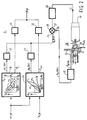
- FIG. 1 shows an embodiment of an electronic continuously variable transmission.
- the transmission 1 comprises a primary shaft 2, on which a primary pulley in the shape of primary pulley halves 3 and 4 is provided, said pulley half 3 being fixedly mounted on the primary shaft 2 and said primary pulley half 4 being movable on the shaft 2.
- the axially movable pulley 4 is movable by exerting a hydraulic pressure in a cylinder space 5.
- the control of the pressure in the cylinder space 5 takes place by a primary control unit 6 connected to the cylinder space 5, the function of said control unit being to adjust the radius of a driving belt 7 provided between the pulley halves 3 and 4 by controlling the pressure in the cylinder space 5.
- the transmission 1 furthermore comprises a secondary shaft 8, on which a pulley having secondary pulley halves 9 and 10 is provided, said pulley half 9 being fixedly mounted on the shaft 8 and said pulley half 10 being movably provided on the shaft 8.
- the pulley half 10, which is axially movable on the shaft, is moved by exerting a pressure in a cylinder space 11 connected to secondary electronic control unit 12.
- the control units 6 and 12 respectively are connected to the cylinder spaces 5 and 11 respectively by means of lines 13 and 14 respectively.
- the tension in the driving belt 7, which is furthermore provided between the secondary pulley halves 9 and 10, is maintained in that the secondary electronic control unit 12 exerts a suitable pressure in the cylinder space 11.
- the transmission ratio or the tension force in the driving belt 7, as the case may be, is hydraulically influenced by the control units 6 and 12 respectively.
- the control units 6 and 12 contain primary and secondary moving means to be further discussed hereafter.
- Said moving means do not necessarily have to be designed for influencing the transmission ratio and the tension force in a hydraulic manner, but it is conceivable that said moving means are of an electro-mechanical nature, and for that purpose comprise electro-mechanical converters, so as to enable an influencing of the transmission ratio or the tension force, as the case may be, by moving the pulley halves 4 or 10, as the case may be.
- the electro-mechanical primary and secondary moving means may e.g. contain a worm wheel to be rotated, by means of which worm wheel the pulley halves 4 and 10 are moved in axial direction.
- the hydraulic version of the primary and secondary moving means will be explained in more detail hereafter.
- the transmission 1 furthermore contains a motor 15 coupled to the primary shaft 2, which motor is controlled by means of a throttle 16 coupled to an accelerator pedal (not shown), which receives an electric signal from a terminal ( ⁇ ), which is connected to the primary electronic control unit 6.
- the transmission 1 furthermore contains further electronic control means 17, which are connected to a terminal (T pr ) of the secondary electronic control unit 12.
- the output signal of said further control means 17 is led, via a command input (C), to clutch means 18 coupled to the secondary shaft 8.
- the clutch means 18 transmit the torque eventually controlled by the transmission to the wheels (not shown) of a vehicle.
- the clutch or lock-up means 18 are engaged or disengaged, as the case may be, by means of a signal on the command input (C), said signal being derived, by further electronic control means 17 yet to be explained, from a signal on the terminal (T pr ), which in turn can be derived from the control unit 12.
- the clutch or lock-up means 18 e.g. a torque converter
- the secondary pulley when seen in the driving direction. It will be apparent, however, that within the framework of the invention said means 18 may also be provided in another configuration or at another location in the transmission, e.g. on the primary shaft, without any problem.
- FIG. 2 shows a fully elaborated preferred embodiment of the primary electronic control unit 6.
- the control unit 6 are connected to a terminal ( ⁇ ) and to a terminal (N s ), and contain first selection means 20 and second selection means 21, which are connected, via respective adjustable damping means 22 and 23, to the summing input 24 of a differentiator 25.
- Said differentiator 25 furthermore contains a differential input 26 and an output 27, which is coupled, via a PID-controller 28, to primary moving means 29.
- Said primary moving means 29, which are hydraulic moving means in the illustrated embodiment, have an ingoing line 30 and an outgoing line 13, in which the hydraulic pressure for the cylinder space 5 is generated.
- the line 13 is coupled, via a converter 31, to the differential input 26 of the differentiator 35.
- the selection means 20 and 21 respectively have outputs ( ⁇ E ) and ( ⁇ var ), which are interconnected via adjustable damping means 32 and 33 respectively, and which are connected to the terminal ( ⁇ ), which is connected to the throttle 16 containing adjusting means.
- an output signal N p (DV) is derived on the basis of the signal ( ⁇ ) in a manner to be further described hereafter, said output signal forming a measure for the desired value of the rpm of the primary shaft 2.
- Said signal is offered to the differentiator via either damping means 22 or 23, which reduces the variation in the signal it is supplied, to which differentiator a signal N p (MV), i.e. the measured value of the rpm of the primary shaft 2, is supplied, also via the differential input 26, on the basis of which the difference signal is made available to the output 27 in the differentiator 25.
- the primary moving means 29 are arranged such that they reduce a pressure P sec prevalent in the line 13, in such a manner that in said line a pressure P prim is prevalent, by means of which the pressure in the cylinder space 5, and thus the transmission ratio, is adjusted.
- a signal to be supplied to the differential input 26 is converted, said signal containing a measure for the measured value N p (MV), which is a measure for the primary rpm measured.
- the first selection means 20 contains a memory, in which characteristics are stored which contain data comprising the motor torque values (T m ) associated with the relevant position ( ⁇ ) of the accelerator pedal versus the values (N p ) of the rpm's of the primary shaft.
- T m motor torque values
- N p values of the rpm's of the primary shaft.
- the characteristic trend of said data is schematically illustrated in block 20.
- the selection means 20 will furthermore contain a memory, in which data are stored comprising the connection between the values of the rpm (N p ) of the primary shaft 2 and the corresponding adjustments of the engine throttle.
- the selection means 21 are selected, which contain a memory in which data are stored which comprise a desired connection between the value (N s ) of the rpm of the secondary shaft 8 and the value (N p ), which represents the rpm of the primary shaft 2.
- This connection is schematically illustrated in block 21.
- This curvilinear, parabolic connection which lies between extreme values of the transmission ratio i, which is defined as N p : N s , is also dependent on the manner in which, when the rpm of the secondary shaft 2, which is generally proportional to the vehicle speed, varies, the corresponding desired value N p (DV) of the rpm of the primary shaft varies in dependence on ( ⁇ ).
- the value (N s ) is derived from a signal present on a terminal (N s ), which is connected to means (not shown) for measuring the rpm of the secondary shaft, and which contains a measure for said rpm.
- the value of N p (DV) thus selected on the basis of N s is led to the control loop via the output of the selection means 21, in which circuit the primary moving means 29 are incorporated.
- Furthermore data will be stored in a memory of the selection means, which data represent the desired connection between N p (DV) and the corresponding throttle adjustment ⁇ var .
- the signal which contains a measure for ⁇ var is supplied to terminal ⁇ via the damping means 33.
- the manner in which the operating mode of the transmission is selected, by selecting the first selection means 20 or the second selection means 21, as the case may be, may take place either manually or in a manner whereby, when the accelerator pedal is influenced in an even manner, an automatic selection is made for the first selection means, and whereby in case of a so-called "kickdown" on the accelerator pedal the option of a normal or a sporting performance is automatically selected by the selection of the selecting means 21,
- the further selection of a desired normal or sporting performance, in case the selection means 21 have been selected may e.g. be done manually.
- the second selection means will thereby select such an N p (DV) with each N s that a constant transmission ratio is achieved.
- N p (DV) is a desirable addition, in particular when the transmission is used in vehicles.
- the driver of the vehicle would thereby have an option to interfere with the control, e.g. manually, by setting a desired transmission ratio N e /N s which is constantly set by second selection means 21, in that case by constant selection of the value N p (DV).
- the various set constants and time constants in the PID-controller 28 can be influenced by e.g.
- the various action in the controller 28 can be made dependent on the values of e.g. the parameters ⁇ , N s , N p (DV), ⁇ E or ⁇ var .
- the controller 28 may furthermore be self-learning.
- the converter 31 is arranged in such a manner that it could determine the rpm N p (MV) of the primary shaft 2 on the basis of the pressure P prim in the line 13, which pressure is proportional to the transmission ratio, given the known value N s of the rpm of the secondary shaft 8.
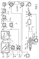
- FIG. 3 shows the podsible arrangement of the secondary electronic control unit 12.
- the control unit 12 contains memory/processing means 34 having an input connected to the terminal and an input connected to the terminal (N m ). Furthermore the means 34 have an output (T m ).
- the control unit 12 furthermore has first correction means 35, with a first input 36 connected to the terminal (T m ) and a second input 39 connected to an output 37 of a first arithmetic unit 38.
- Said arithmetic unit 38 has a first input 40 connected to the terminal (N m ) and a second input 41 connected to the terminal N p .
- the signal on the input 39 contains a measure for the quotient of N p and N m .
- the control unit 12 furthermore contains a second arithmetic unit 42 having a first input 43 connected to the terminal (N p ) and a second input 44 connected to a terminal (N s ).
- the arithmetic unit has an output 45, from which a signal can be derived which contains a measure for the transmission ratio, which is defined as the quotient of N p and N s .
- a third arithmetic unit 46 has two inputs 47 and 48, the first input 47 of which is connected to the terminal T pr and the second input 48 of which is connected to the output 45 of the second arithmetic unit 42.
- control unit 12 contains a fourth arithmetic unit 49 having an input 50 connected to the output 45 and an output 51, from which a signal can be derived which contains a measure for the radius R sec of the driving belt 7 between the secondary pulley halves 9 and 10, and a fifth arithmetic unit 52 having a first input 54 connected to an output 53 of the third arithmetic unit 46 and a second input 55 connected to the output 51. From an output 56 of the fifth arithmetic unit 52 a signal can be derived, in a manner to be explained hereafter, which contains a measure for the required pressure P sec , on the basis of which the tension in the driving belt 7 is controlled by adjusting the pressure in the cylinder space 11.
- the illustrated embodiment furthermore contains a sixth arithmetic unit 57 incorporated in the control unit 12, which has an input 58 and an output 59, and a seventh arithmetic unit 60 having a first input 61, a second input 62, and an output 63.
- the input 58 is connected to the terminal (N s )
- the second input 62 is connected to the output 59
- the first input 61 of the arithmetic unit 60 is coupled to the output 56 of the fifth arithmetic unit 52, via an arithmetic unit 64 incorporated in the control unit 12, said arithmetic unit 64 having a first input 65 connected to the output 56, a second input 66 and an output 67.
- Adjustable damping means 68 are provided between the output 67 and the input 61. Like the aforesaid adjustable damping means 22, 23, 32, 33 the adjustable damping means 68 contain electronic means, on the basis of which an amplitude variation in the input signal is reduced, whereby in general the reduction in a rising gradient of the input signal will be different from a reduction with regard to a decreasing gradient in the input signal in question.
- the output 63 of the seventh arithmetic unit may be coupled, via an adjustable limiter 168, to an input 69 of a differentiator 70.
- the differentiator 70 forms part of a control loop, in which there is furthermore incorporated a PID-controller 72 coupled to an output 71 of the differentiator 70, said PID-controller having an output 73 which is connected to secondary moving means 74.
- the moving means 74 are provided with an ingoing line 75, which is coupled to a pump (not shown) and an outgoing line 76.
- the pressure P sec (MV) in the line 76 is controlled in dependence on the output signal on the output 73, in that the line 76 is connected to a converter 77, which contains an output 78 which is connected to a differential input 79 of the differentiator 70.
- the converter 77 is arranged in such a way that it effects a conversion of the hydraulic pressure in the outgoing line 76 to a signal on the output 78, which signal will generally be electrical and which is suitable for being processed by the differentiator 70.
- the pressure P sec (MV) forms the value thus measured of the pressure in the cylinder space 11, by means of which the tension force in the driving belt 7 is controlled on the basis of the parameters ⁇ , N m , N p or N s . Also the actions in the PID-controller 72 are adjusted such that they ensure an optimum and stable influencing of the pressure P sec (MV).
- the starting point in the operation of the secondary electric control unit 12 is formed by the data stored in the memory of said control means, said data comprising the values T m associated with the motor torque values N m of the engine rpm, in dependence on the possible settings of the engine throttle 16.
- T m associated with the motor torque values N m of the engine rpm
- T pr On the basis of data stored in a memory of the first correction means 35, which data comprise the connection between the torque T pr produced at the primary pulley of the motor, and the quotient of N p and N m an estimate is made of T pr , which is supplied to the input 47.
- T pr and i On the basis of the signal supplied to the second input 48, which contains a measure for the transmission ratio, the product of T pr and i is determined in the third arithmetic unit 46, and said product is supplied to the input 54 in the shape of a signal T sec .
- a computation is carried out in the fifth arithmetic unit 52, the result of which is supplied to the input 65 in the shape of an estimate for P sec .
- a signal is supplied which corresponds with e.g. a pressure of 2 bar, which in the arithmetic unit 64 is added to the signal on the input 65 and which is then supplied to the input 61 of the arithmetic unit 60 via the adjustable damping means 68.
- T sec represents the torque to be supplied to the vehicle
- » is the coefficient of friction
- R sec is the secondary radius of the driving belt
- a s is the effective surface, with which the pressure in the secondary moving means is controlled by means of a plunger provided therein
- C is a constant.
- the arithmetic unit 60 subtracts the signal on the input 62 from the signal on the input 61, the difference being supplied to the output 63.
- the factor P sec (CENTR) will play an important role, in particular with higher secondary rpm's of the shaft 8.
- a desired secondary pressure P sec (DV) is supplied to the differentiator 70, said pressure being a function of the parameters ⁇ , N m , N p and N s .
- the circuit will be arranged in such a manner that when the signal on the output 73 is zero the secondary pressure will be maximal, in order that, irrespective of a possible failure in the functioning of the control means 12, the tension of the driving belt is controlled such that the functioning of the transmission 1, be it not optimal, is ensured.
- FIG. 4 shows the possible arrangement of the further electronic control means 17, and a part of the clutch/lock-up means 18.
- the further electronic control means 17 contain a ninth arithmetic unit 80 having an input 81 connected to the terminal T pr and an output 82.
- the output 82 is connected to a first input 83 of a tenth arithmetic unit 84, which furthermore has a second input 85 and an output 86.
- the signal on the input 85 represents an additional pressure, which is added to the signal P thr on the input 83, whereby the eventual sum is made available to the output 86.
- the output 86 is coupled to the terminal (C) via adjustable damping means 87 (if present) and a converter 88.
- Said converter 88 converts the desired value of the pressure P thr into a signal which is suitable for influencing a valve 89 incorporated in the block 18.
- the converter 88 will generally be provided with a suitably adjustable PID-controller for that purpose.
- the valve 89 has an ingoing line 90, in which a hydraulic pressure P sec is realised by means of a pump (not shown) and an outgoing line 91, in which a pressure influenced by means of the further electronic control means 17 is realised for a valve 92, which may e.g. be manually controlled.
- the signal P thr may also be used for engaging a clutch/torque converter 93. If required the engagement of the clutch/torque converter 93 may be made dependent on the operating mode connected with the "economical", "normal” or “sporting" driving style.
- the engagement of the clutch/lock-up of the torque converter 93 can furthermore be made dependent on certain requirements being met by the aforesaid parameters or on a combination of the aforesaid parameters.
- Said engagement may e.g. be made dependent on certain limits being exceeded, or the reverse, by the parameters or the parameter combinations.
- parameters or parameter combinations include: ⁇ , d ⁇ /dt, i, N s , N p , N m /N p , dN s /dt or for example the temperature of e.g. the brakes or the slip torque of the belt.
- the limiting values may be made dependent again on the specific operating mode which is required.
- valve 89 may be incorporated in a control loop, in which case the line 89 also must be connected to a converter (not shown), however, which is to be connected to a differentiator (not shown) to be provided between the adjustable damping means 87 and the converter 88.
- the previously explained memories in the means 20, 21, 34 and 35 may e.g. be in the shape of a rom, prom, an E-prom or an EE-prom.
- the electronically controlled continuously variable transmission explained above may be extended in a simple manner into an even more advanced transmission.
- suitable signals e.g. the secondary electronic control unit 12, said signals containing a measure for any torque variations caused by the motor or e.g. the road.
- Such torque variations may namely lead to undesirable slip of the driving belt 7 across the various pulley halves.
- Said slip may be prevented in that, even before said torque variations reach the transmission, the secondary pressure is influenced, and generally enhanced, in such a manner that such torque variations do not lead to said undesirable slip. It is necessary in that case that the possibility of torque variations occurring is recognized at an early stage. It is possible to anticipate the torque variations caused by the motor when the motor torque field of the motor used is known.
- This motor torque field is stored in the means 34 and is thus used in the embodiment of Figure 3 to realise a certain adaptation of the secondary pressure, given a certain variation in the position of the throttle and the change of the motor torque connected therewith.
- a normal operation of the transmission i.e. the drive position
- the various operating situations such as: “low”, “medium” or “overdrive”
- the secondary electronic control unit 12 may thus be arranged in such a manner that this fact is taken into account, so that the tension in the driving belt 7 is at all times optimally adapted to the torque to be transmitted.
- Indicators that are in principle suitable include:
- the above indicators are in principle usable, but they provide measuring magnitudes which occur substantially simultaneously with the occurring torque variations. Measuring magnitudes which on the other hand anticipate torque variations in the transmission include:
- Information that anticipates even further is provided by measuring the unevenness of the road surface by means of e.g. microwaves or laser-doppler sensors.
- Said sensors are blank contact transducers, which are already used with so-called active suspension systems. Since the information provided by said sensors anticipates so far ahead, ample computing time and control time is available so as to have the secondary pressure adjusted at the correct moment. It appears that even at a speed of 100 km/h a period of about 18 milliseconds is still available.
- Sensor means 94 of the type explained above are schematically indicated in Figure 3. In the illustrated embodiment of the secondary electronic control unit 12 said sensor means 94 are connected to a third input 95 of the seventh arithmetic unit 60, so as to influence the secondary pressure additionally by means of the signal on the third input.
- the electro-mechanical means explained above with reference to Figures 2, 3 and 4, viz. the primary moving means 29, the secondary moving means 74 and the valve 89 may, as already said before, be of electromechanical design.
- a preferred embodiment of such electromechanical means provided with reference numeral 96 is illustrated in Figure 5.
- the means 96 illustrated in this embodiment comprise a valve body 97, which is axially movable within a space 98 under the influence of a movable core 100 accommodated in a coil 99.
- the valve body 97 bears against a spring 101, whose bias can be set by means of an adjusting screw 102.
- the construction of the valve body 97 is such that said valve body narrows in the space 98, from an effective surface A1 to an effective surface A2, which is smaller than A1.
- Lines 103 and 104 terminate in the space 98, whose passages may be controlled by moving the valve body 97.
- a pump (not shown) may e.g. be connected to the line 103, whereby the line 104 can be used as a blow-off for the fluid to be delivered by the pump.
- By driving the coil 99 it is possible to influence the axial position, and thus the passage, so that in that case a pressure is effected in the line 103 which is dependent on the current through the coil 99. If a fluid pressure is present in the space 98 a net force against the spring force of the spring 101 will co-operate with the force exerted by the coil 99, and a required position of the valve body 97 will be adjusted on the basis of this equilibrium of forces.
- the net force produced by the hydraulic pressure in the space 98 works against the spring pressure, since the effective surface A1 is larger than the effective surface A2.
- the electro-mechanical means 96 thus work directly, i.e. they function as a direct converter of the electric current I into a required hydraulic pressure.
- the use of a pilot valve or an auxiliary valve, as was usual, has become redundant as a result of this direct control method.
- the electromechanical means 96 will be incorporated in a control loop, in order to reduce their sensitivity to the effect that the pressure in the space 98 has on control behaviour of said means, a converter 105 connected to the line 103 for converting the hydraulic pressure in the line 103 into a corresponding electric signal P(MV) being present in said control loop.
- Said control loop furthermore contains a differential amplifier 106 having two inputs, viz. P(MV) and P(DV), and one output 107, to which the coil 99 is connected. As long as the differential amplifier detects a differential signal between the measured value P(MV) and the required value P(DV), said amplifier will effect a current through the coil 99 so as to move the valve body 97, until an equilibrium has been adjusted and both signal are equal to each other.
- a very important advantage from a point of view of safety is that, in the unlikely event of a power failure, the electro-mechanical means automatically assume a position, under the influence of the spring, in which a safe high pressure is set. In that case the transmission keeps functioning in spite of the power failure.
- the electro-mechanical means may be designed such that in the event of a power failure a constant lower pressure is set. Besides the electro-mechanical means also additional control means may be provided which, only in the event of a power failure, set the high or low pressure adjusted by the electro-mechanical means to a required pressure level. Two possible embodiments are illustrated in Figures 6 and 7.
- FIG. 6 shows a primary electronic control unit 6 which, insofar as it corresponds with Figure 2, has been given the same numerals.
- the primary moving means 29 are again in the shape of hydraulic moving means and have an ingoing line 30 with a P sec and an outgoing line 13 with the set pressure P prim .
- Hydraulic medium can be discharged via an outgoing line 111.
- the valve body 112 will move to the right under the influence of the spring 113, as a result of which the ingoing line 30 is no longer in contact with the ingoing line 13.
- There is a connection between the line 13 and the line 111 so that hydraulic medium will flow from the line 13 via the line 111.
- control according to Figure 6 is furthermore provided with an on/off solenoid 114 and a safety valve 117.
- the safety valve 117 is placed in the line 13 of P prim .
- the on/off solenoid 114 is provided with an ingoing line 115 and an outgoing line 116, which is coupled to the safety valve 117.
- FIG. 7 shows a secondary electronic control unit which, insofar as it corresponds with Figure 2, has been given the same numerals.
- the moving means 74 are provided with an ingoing line 75, which is again coupled to a pump (not shown) and an outgoing line 76.
- the moving means 74 are designed such, however, that in the event of a power failure the connection between the ingoing line 75 (P sec ) and the outgoing line becomes maximal, because in the event of a power failure the valve body 121 is completely pushed to the right in Figure 7 under the influence of the spring 122.
- P sec is set to a safe pressure in the line 75, as a result of the large discharge of medium via the line 76. Said P sec cannot be optimal, however, e.g.
- a hydraulic auxiliary valve 123 is provided in the discharge line 76.
- Said auxiliary valve 123 has a valve body 124 and a spring 125. Furthermore the pressure of the discharge line 76 acts on the valve 124 at 126. Said pressure of the discharge line 76 at 126 acts against the spring 125. On the other hand the spring 125 is supported again at 127 by the pressure P sec in the line 75.
- electro-mechanical means may be provided with several supply and/or discharge lines, as well as with control edges.
- the valve body 97 itself may also serve as a core for the coil 99.
- the electro-mechanical means in particular those wherein the valve body is directly connected to the core of the coil or wherein the valve body itself functions as a core, instability of hysteresis may occur when the coil is driven with a certain current. According to the invention this can be largely prevented, however, by providing a dither frequency on the current.
- control may furthermore be self-learning, in such a manner that the driving current, without control steps, is directly taken to the required value, after which the control takes over the current adjustment.
Landscapes
- Engineering & Computer Science (AREA)
- Mechanical Engineering (AREA)
- Combustion & Propulsion (AREA)
- Chemical & Material Sciences (AREA)
- Transportation (AREA)
- General Engineering & Computer Science (AREA)
- Automation & Control Theory (AREA)
- Control Of Transmission Device (AREA)
- Valve Device For Special Equipments (AREA)
- Reduction Or Emphasis Of Bandwidth Of Signals (AREA)
- Magnetically Actuated Valves (AREA)
- Gear-Shifting Mechanisms (AREA)
- Valves And Accessory Devices For Braking Systems (AREA)
- Earth Drilling (AREA)
Claims (25)
- Variateur en continu commandé électroniquement (1), muni d'une courroie d'entraînement (7) disposée entre une poulie primaire montée sur un arbre primaire (2) et une poulie secondaire (9, 10) montée sur un arbre secondaire (8), chaque poulie présentant des moitiés de poulie conique correspondantes (3, 4 et 9, 10) et au moins l'une de ces moitiés de poulie correspondantes étant mobile axialement à l'aide de moyens de déplacement primaire et secondaire (29 et 74) raccordés respectivement à une moitié de poulie primaire et à une moitié de poulie secondaire, lequel variateur en continu comprend une unité de commande électronique (6) pour régler le rapport de transmission, caractérisé en ce qu'il est prévu une unité de commande électronique supplémentaire (12) pour commander la tension dans la courroie d'entraînement (7), les moyens de déplacement primaire (29) étant accouplés à l'unité de commande électronique (6) et les moyens de déplacement secondaire (74) étant accouplés à l'unité de commande électronique supplémentaire (12) et les unités de commande électronique (6 et 12) étant séparées l'une de l'autre.
- Variateur selon la revendication 1, caractérisé en ce que l'unité de commande électronique primaire (6) comprend des sélecteurs (20, 21) dans lesquels sont mémorisées des données réciproquement différentes entre elles, ces données concernant une certaine sélection optimum par rapport au mode de fonctionnement du variateur.
- Variateur selon la revendication 2, caractérisé en ce qu'un signal est amené à une entrée du premier sélecteur (20), lequel signal contient une mesure de la position (α) d'une pédale d'accélérateur d'un moteur accouplé au variateur et en ce qu'en fonction du type de moteur une sélection optimum pour la valeur momentanément souhaitée de la vitesse de rotation de l'arbre primaire (2) est effectué à partir des données stockées dans la mémoire, les données comprenant les voleurs du moment de couple associées à le position appropriée de la pédale d'accélérateur par rapport eux valeurs (Np) de la vitesse de rotation correspondante de l'arbre primaire et en ce que la sélection est transmise à une sortie accouplée eux moyens de déplacement primaire (29) de façon à agir sur le rapport de variation.
- Variateur selon la revendication 2 ou 3, caractérisé en ce qu'un signal est amené à une entrée du second sélecteur (21), lequel signal contient une mesure de la position (α) d'une pédale d'accélérateur d'un moteur accouplé au variateur, ce en quoi sur la base de ce signal ainsi que d'un signal fourni à une entrée du second sélecteur (21), signal qui contient une mesure pour la vitesse de rotation (Ns) de l'arbre secondaire (8), il est procédé à une sélection optimum pour la valeur momentanément souhaitée de la vitesse de rotation de l'arbre primaire (2) à partir des données stockées dans une mémoire du second sélecteur (21), ces données comprenant une liaison souhaitée entre les valeurs de la vitesse de rotation de l'arbre secondaire (6) et la vitesse de rotation dc l'arbre primaire (2) et en ce que la sélection est amenée à une sortie accouplée aux moyens de déplacement primaire (29) de façon à agir sur le rapport de variation.
- Variateur selon la revendication 3 ou 4, caractérisé en ce que la transmission est dotée de moyens d'amortissement réglables (22, 23) qui sont connectés entre le sortie des premier ou second sélecteurs (20, 21) et les moyens de déplacement primaire (29).
- Variateur selon l'une quelconque des revendications 3 - 5, caractérisé en ce qu'en fonction de la valeur requise de la vitesse de rotation de l'arbre primaire (2), le réglage réel de la vanne papillon est choisi à partir des données stockées dans la mémoire du sélecteur respectif (20, 21), lesquelles données comprennent la liaison entre les voleurs de la vitesse de rotation (Np) de l'arbre primaire (2) et les réglages éventuels correspondants (β) de la vanne papillon (16) du moteur, lequel réglage réel de la vanne papillon doit être amené aux moyens de réglage de la vanne papillon accouplés au sélecteur (20, 21).
- Variateur selon la revendication 6, caractérisé en ce qu'il est muni de moyens d'amortissement réglables (32, 33) qui sont montés entre la sortie des premier et second sélecteurs (20, 21) et les moyens de réglage de la vanne papillon.
- Variateur selon l'une quelconque des revendications 1 à 7, caractérisé en ce que l'unité de commande électronique secondaire (12) contient une mémoire (34) dans laquelle sont stockées des données qui comprennent les valeurs liées aux valeurs du moment de couple, de la vitesse de rotation du moteur en fonction des réglages de la vanne papillon du moteur (16) et en ce que l'unité de commande (12) comporte deux entrées pour fournir un signal contenant une mesure de la position réelle (β) de la vanne papillon (16) à la première entrée et pour fournir un signal (Nm) contenant une mesure de la vitesse de rotation réelle à la seconde entrée, ainsi que des moyens de traitement (34) raccordés à la mémoire (34) pour fournir un signal supplémentaire contenant une mesure du moment de couple produit par le moteur à la sortie des moyens de traitement (34) et en ce que la sortie des moyens de traitement (34) est accouplée aux moyens de déplacement secondaire (74) pour la commande de la tension de la courroie d'entraînement en fonction du signal ultérieur.
- Variateur selon la revendication 8, caractérisé en ce que l'unité de commande secondaire (12) contient des premiers moyens de correction (35) munis de deux entrées (36, 39) et une sortie et une première unité arithmétique (38) munie de deux entrées (40, 41) et d'une sortie (37), la première entrée (40) de l'unité arithmétique (38) étant connectée à la seconde entrée de l'unité de commande secondaire (12), la seconde entrée (41) de l'unité arithmétique (38) étant connectée à une borne (Np) à laquelle doit être amené un signal qui contient une mesure pour la valeur du moment de couple (Np) de l'arbre primaire (2) et à la sortie de l'unité arithmétique (38) raccordée à la seconde entrée (39) des premiers moyens de correction (35) un signal étant produit qui contient une mesure pour le quotient de (Np) et (Nm), lu première entrée (36) des premiers moyens de correction (35) étant connectée à la sortie du moyen de traitement (34) et la sortie des premiers moyens de correction (35) étant accouplée aux moyens de déplacement secondaire (74).
- Variateur selon la revendication 8 ou 9, caractérisé en ce que l'unité de commande secondaire (12) contient une seconde (42) et une troisième (41) unités arithmétiques, chaque unité étant munie de deux entrées et d'une sortie, la première entrée (43) de la seconde unité arithmétique (42) étant raccordée à une borne (Np) sur laquelle le signal doit être amené et contenant une mesure de la valeur de la vitesse de rotation (Np) de l'arbre primaire (2) et la seconde entrée (44) de la seconde unité arithmétique (42) étant connectée à une borne (Ns) sur laquelle un signal doit être amené et contenant une mesure de la valeur de la vitesse de rotation (Ns) de l'arbre secondaire (8) et un signal étant produit à la sortie (45) de la seconde unité arithmétique (42) raccordée à la seconde entrée (48) de la troisième unité arithmétique (46) contenant une mesure du rapport de variation (i), la première entrée (47) de la troisième unité arithmétique (46) étant accouplée à la sortie des premiers moyens de correction (35) et la sortie (53) de la troisième unité arithmétique (46) étant accouplée aux moyens de déplacement secondaire (74).
- Variateur selon la revendication 10, caractérisé en ce que la seconde unité de commande (12) contient une quatrième unité arithmétique (49) avec une entrée (50) et une sortie (51) et une cinquième unité arithmétique comportant deux entrées (54, 55) et une sortie (56), l'entrée (50) de la quatrième unité arithmétique (49) étant raccordée à la sortie (45) de la seconde unité arithmétique (42) de façon à produire un signal à la sortie (51) de la quatrième unité arithmétique (49) qui contient une mesure du rayon secondaire (Rs) de la courroie d'entraînement (7) qui est mobile entre les moitiés de poulie secondaire, la sortie (51) de la quatrième unité arithmétique (49) étant raccordée à la seconde entrée (55) de la cinquième unité arithmétique (52) et la première entrée (54) de la cinquième unité arithmétique (52) étant raccordée à la sortie (53) de la troisième unité arithmétique (46) et la sortie (56) de la cinquième unité arithmétique (52) étant accouplée aux moyens de déplacement secondaire (74).
- Variateur selon la revendication 10 ou 11, caractérisé en ce que l'unité de commande secondaire (12) contient une sixième unité arithmétique (57) comportant une entrée (58) et une sortie (59) et une septième unité arithmétique (60) avec doux entrées (61, 62) et une sortie (63), l'entrée (58) de la sixième unité arithmétique (57) étant connectée à la borne (Ns), la sortie (59) de la sixième unité arithmétique (57) étant connectée à la seconde entrée de la septième unité arithmétique (60) et la première entrée (61) de la septième unité arithmétique (60) étant accouplée à la sortie (53) de la troisième unité arithmétique (46) de façon à réduire, pour des vitesses de rotation supérieures de l'arbre secondaire (8), la mesure dans le signal de sortie (63) de la septième unité arithmétique (60) qui commande la force de tension de la courroie d'entraînement (7).
- Variateur selon l'une quelconque des revendications 8 - 12, caractérisé en ce que l'unité de commande électronique secondaire (12) contient au moins un limiteur qui est raccordé entre la sortie des moyens de traitement (34) et des moyens de déplacement secondaire (74).
- Variateur selon l'une quelconque des revendications 8 - 13, caractérisé en ce que la variateur contient une huitième unité arithmétique (64) accouplée à la sortie des moyens de traitement (34), cette unité arithmétique comportant une entrée (65) et une sortie (67), la variateur contenant également des moyens d'embrayage (18) accouplés à l'arbre secondaire (8), qui à la commande du signal de commutation sur une entrée de commande (C) embrayent ou désembrayent, en ce que l'entrée (65) de la huitième unité arithmétique (64) est accouplée à la sortie (T) des moyens de traitement (34) et en ce que l'entrée de commande (C) des moyens d'embrayage (18) est accouplée à la sortie (67) de le huitième unité arithmétique (64).
- Variateur selon la revendication 14, caractérisé en ce que la variateur contient un limiteur raccordé entre la sortie (67) de la huitième unité arithmétique (64) et l'entrée des moyens d'embrayage (18).
- Variateur selon l'une quelconque des revendications précédentes, caractérisé en ce que l'unité de commande électronique secondaire (12) contient des moyens de capteurs accouplés aux moyens de déplacement secondaire (74) de façon à produire un signal contenant une mesure des variations du moment de couple indésirables, lesquelles, dues à l'état de la surface de la route ou du moteur, parviennent au variateur, et on ce que l'unité de commande électronique secondaire (12) est agencée de manière telle qu'avant que les variations du moment de couple ne parviennent eux variateur, la tension de la courroie d'entraînement (7) a été réglée en conséquence.
- Moyens électromécaniques (96) utilisés dans le variateur selon l'une quelconque des revendications précédentes, caractérisés en ce que ces moyens (96) contiennent un corps de soupape (97) mobile axialement et une bobine (99) avec un noyau mobile (100) qui est raccordé au corps de soupape (97), la position du corps de soupape (97) étant influencée par l'excitation de la bobine (99) de façon à fixer un ou plusieurs niveaux de pression.
- Moyens électromécaniques (96) selon la revendication 17, caractérisés en ce que le corps de soupape (97) sort également de noyau et en ce que, de ce fait, il est partiellement logé à l'intérieur de la bobine.
- Moyens électromécaniques (96) selon la revendication 17 ou 18, caractérisés en ce que le corps de soupape (97) comporte au moins une surface (A1) dans un espace (98) devant être rempli de fluide hydraulique de façon à exercer une force hydraulique sur le corps de soupape (97), laquelle force combinée à la force produite par la commande de la bobine (99) sert à influencer la position du corps de soupape (97) de façon à fixer un ou plusieurs niveaux de pression.
- Moyens électromécaniques (96) selon l'une quelconque des revendications 17 - 19, caractérisés en ce que ces moyens (96) comportent un ressort (101) accouplé au corps de soupape (97) qui déplace le corps de soupape (97) dans la direction de la position où est fixée la pression extrême.
- Moyens électromécaniques (96) selon l'une quelconque des revendications 17 - 19, caractérisés en ce que la bobine (99) fournit une fréquence de tremblement sur le courant de façon à stabiliser les moyens électromécaniques (96).
- Variateur selon l'une quelconque des revendications précédentes, caractérisé en ce que le variateur est muni de moyens de commande supplémentaires (17) lesquels en cas de panne de courant agissent sur la pression fixée par les moyens électromécaniques (96).
- Variateur selon la revendication 22, caractérisé en ce que les moyens de commande supplémentaires comprennent une première soupape de sécurité (117) laquelle, en cas de panne de courant, fixe la pression établie par les moyens électromécaniques (96) afin d'agir sur le rapport de variation à modifier progressivement de façon à empêcher les changements brusques dans le rapport de variation.
- Variateur selon la revendication 22, caractérisé en ce que des moyens de commande supplémentaires comprennent une seconde soupape de sécurité (123) laquelle en cas de panne de courant fixe la pression commandée par les moyens électromécaniques (96) pour agir sur la tension de la courroie d'entraînement (7) à une pression souhaitée.
- Variateur selon l'une quelconque des revendications 22 - 24, caractérisé en ce que des moyens de commande supplémentaires comprennent également un solenoïde (114) marche/arrêt.
Priority Applications (1)
| Application Number | Priority Date | Filing Date | Title |
|---|---|---|---|
| EP19940200110 EP0595793A3 (en) | 1990-04-12 | 1991-03-08 | Electro-mechanical hydraulic pressure control means |
Applications Claiming Priority (2)
| Application Number | Priority Date | Filing Date | Title |
|---|---|---|---|
| NL9000860A NL9000860A (nl) | 1990-04-12 | 1990-04-12 | Elektronisch geregelde continu variabele transmissie. |
| NL9000860 | 1990-04-12 |
Related Child Applications (1)
| Application Number | Title | Priority Date | Filing Date |
|---|---|---|---|
| EP94200110.8 Division-Into | 1994-01-18 |
Publications (2)
| Publication Number | Publication Date |
|---|---|
| EP0451887A1 EP0451887A1 (fr) | 1991-10-16 |
| EP0451887B1 true EP0451887B1 (fr) | 1995-06-07 |
Family
ID=19856912
Family Applications (2)
| Application Number | Title | Priority Date | Filing Date |
|---|---|---|---|
| EP91200513A Expired - Lifetime EP0451887B1 (fr) | 1990-04-12 | 1991-03-08 | Variateur continu de vitesse commandé électroniquement |
| EP19940200110 Withdrawn EP0595793A3 (en) | 1990-04-12 | 1991-03-08 | Electro-mechanical hydraulic pressure control means |
Family Applications After (1)
| Application Number | Title | Priority Date | Filing Date |
|---|---|---|---|
| EP19940200110 Withdrawn EP0595793A3 (en) | 1990-04-12 | 1991-03-08 | Electro-mechanical hydraulic pressure control means |
Country Status (9)
| Country | Link |
|---|---|
| US (2) | US5337628A (fr) |
| EP (2) | EP0451887B1 (fr) |
| JP (2) | JP3247895B2 (fr) |
| KR (1) | KR0145420B1 (fr) |
| AT (1) | ATE123452T1 (fr) |
| CA (1) | CA2039215A1 (fr) |
| DE (1) | DE69110180T2 (fr) |
| ES (1) | ES2074645T3 (fr) |
| NL (1) | NL9000860A (fr) |
Cited By (20)
| Publication number | Priority date | Publication date | Assignee | Title |
|---|---|---|---|---|
| EP0565144A1 (fr) * | 1992-04-06 | 1993-10-13 | Van Doorne's Transmissie B.V. | Transmission à variation continue avec système de commande |
| EP0574968A1 (fr) * | 1992-06-15 | 1993-12-22 | Van Doorne's Transmissie B.V. | Méthode pour influencer le comportement de conduite d'un véhicule avec transmission à variation continue |
| US5846156A (en) * | 1996-03-26 | 1998-12-08 | Robert Bosch Gmbh | Arrangement for adjusting the gear ratio of a continuously adjustable transmission |
| US5871411A (en) * | 1994-04-02 | 1999-02-16 | Robert Bosch Gmbh | Slip controller for a continuously variable transmission |
| US5885178A (en) * | 1995-06-22 | 1999-03-23 | Robert Bosch Gmbh | Electro-hydraulic control means for controlling a hydraulic pressure in a continuously variable loop transmission and the loop transmission containing same |
| GB2329433A (en) * | 1997-09-18 | 1999-03-24 | Rover Group | Electrohydraulic control system for a continuously-variable transmission of a vehicle |
| US5913746A (en) * | 1996-03-20 | 1999-06-22 | Robert Bosch Gmbh | System for adjusting the gear ratio of a continuously variable transmission |
| US6050913A (en) * | 1994-12-28 | 2000-04-18 | Robert Bosch Gmbh | System for adjusting the tension of the belt drive of a belt transmission |
| US6080080A (en) * | 1997-09-30 | 2000-06-27 | Robert Bosch Gmbh | Device and method for adjusting the transmission ratio of a CVT |
| US6146294A (en) * | 1996-09-19 | 2000-11-14 | Robert Bosch Gmbh | Method and device for the operation of a flexible drive mechanism |
| US6168546B1 (en) | 1997-03-26 | 2001-01-02 | Robert Bosch Gmbh | Device and method for controlling the transmittable torque in a CVT |
| WO2001004517A1 (fr) * | 1999-07-10 | 2001-01-18 | Robert Bosch Gmbh | Systeme de reglage hydraulique de la transmission pour une transmission continue variable |
| EP1243817A1 (fr) | 2001-03-23 | 2002-09-25 | Van Doorne's Transmissie B.V. | Transmission à variation continue à commande de pression précise |
| US6547692B1 (en) | 1999-06-12 | 2003-04-15 | Robert Bosch Gmbh | System for adjusting the tension of the continuous belt component of a CVT |
| US6599207B1 (en) | 1999-06-30 | 2003-07-29 | Robert Bosch Gmbh | System for hydraulically adjusting the transmission of a CVT |
| US6623388B1 (en) | 1998-12-22 | 2003-09-23 | Robert Bosch Gmbh | System for adjusting the voltage of a wrapped component of an infinitely variable speed transmission |
| GB2392214A (en) * | 1999-09-24 | 2004-02-25 | Borgwarner Inc | Belt CVT with failsafe and pulley adjusters. |
| US6917868B2 (en) | 2002-03-16 | 2005-07-12 | Robert Bosch Gmbh | Method and device for adjusting a torque output of a power train of a motor vehicle |
| DE10246422B4 (de) * | 2002-03-16 | 2021-02-04 | Robert Bosch Gmbh | Verfahren zum Einstellen einer Drehmomentabgabe eines Antriebsstranges eines Kraftfahrzeuges |
| US11130501B2 (en) * | 2017-07-04 | 2021-09-28 | Baidu Online Network Technology (Beijing) Co., Ltd. | System, method and apparatus for controlling autonomous driving vehicle |
Families Citing this family (56)
| Publication number | Priority date | Publication date | Assignee | Title |
|---|---|---|---|---|
| NL9000860A (nl) * | 1990-04-12 | 1991-11-01 | Doornes Transmissie Bv | Elektronisch geregelde continu variabele transmissie. |
| DE4411553A1 (de) * | 1994-04-02 | 1995-10-05 | Bosch Gmbh Robert | Vorrichtung zur Sensierung einer Drehbewegung und einer Axialverschiebung eines Körpers |
| JP3411707B2 (ja) * | 1995-03-02 | 2003-06-03 | 本田技研工業株式会社 | ベルト式無段変速機の制御装置 |
| NL1001279C2 (nl) * | 1995-09-25 | 1997-03-26 | Doornes Transmissie Bv | Continu variabele transmissie. |
| DE19602033C2 (de) * | 1996-01-20 | 2000-06-21 | Telefunken Microelectron | Verfahren zur Regelung stufenlos verstellbarer Getriebe von Kraftfahrzeugen |
| DE19602032C2 (de) * | 1996-01-20 | 2000-06-15 | Telefunken Microelectron | Verfahren zur Regelung stufenloser Getriebe von Kraftfahrzeugen |
| DE19610216A1 (de) * | 1996-03-15 | 1997-09-18 | Bosch Gmbh Robert | Vorrichtung zur Steuerung eines stufenlosen Getriebes |
| DE19611431B4 (de) * | 1996-03-22 | 2008-02-21 | Robert Bosch Gmbh | System zur automatischen Übersetzungsverstellung |
| DE19632747A1 (de) * | 1996-08-14 | 1998-02-19 | Zahnradfabrik Friedrichshafen | Verfahren zur Drucksteuerung eines CVT |
| BE1010758A3 (nl) * | 1996-11-21 | 1999-01-05 | Vcst Nv | Werkwijze en inrichting voor het sturen van een transmissie-eenheid bij motorvoertuigen. |
| JP3457488B2 (ja) * | 1996-11-25 | 2003-10-20 | 株式会社日立製作所 | 自動車の制御装置 |
| DE19649483B4 (de) * | 1996-11-29 | 2008-06-19 | Robert Bosch Gmbh | Vorrichtung und Verfahren zur automatischen Übersetzungsverstellung |
| JP3422227B2 (ja) * | 1997-07-16 | 2003-06-30 | 日産自動車株式会社 | 無段変速機の制御装置 |
| EP0937914B1 (fr) | 1998-02-23 | 2004-12-01 | Van Doorne's Transmissie B.V. | Transmission à variation continue |
| DE19928292A1 (de) * | 1998-12-22 | 2000-06-29 | Bosch Gmbh Robert | System zur Einstellung der Spannung des Umschlingungsteils eines Umschlingungsgetriebes |
| DE19920378C2 (de) * | 1999-05-04 | 2002-11-07 | Zahnradfabrik Friedrichshafen | Automatisch gesteuertes Getriebe |
| DE19943939A1 (de) * | 1999-09-14 | 2001-03-15 | Volkswagen Ag | Notsteuerung für ein Kraftfahrzeug |
| US6634982B2 (en) * | 1999-12-24 | 2003-10-21 | Aisin Aw Co., Ltd. | Automatic speed changer controller, automatic speed changer control method, and recording medium having program for method recorded thereon |
| DE19963783B4 (de) | 1999-12-30 | 2012-01-19 | Robert Bosch Gmbh | Vorrichtung und Verfahren zur Regelung einer Verstellgeschwindigkeit eines Schaltvorgangs in einem automatisierten, stufenlos verstellbaren Getriebe |
| DE60102030T2 (de) * | 2000-05-03 | 2004-12-02 | Van Doorne's Transmissie B.V. | Stufenlos veränderliches Getriebe mit einer variablen Übersetzungsverhältnis-Überdeckung |
| JP2001330135A (ja) * | 2000-05-23 | 2001-11-30 | Toyota Motor Corp | ベルト式無段変速機の制御装置 |
| EP1167839B1 (fr) | 2000-06-30 | 2004-05-26 | Van Doorne's Transmissie B.V. | Transmission à variation continue et son procédé de commande |
| JP3589198B2 (ja) * | 2000-12-25 | 2004-11-17 | トヨタ自動車株式会社 | 駆動系統の制御装置 |
| DE10101356A1 (de) * | 2001-01-13 | 2002-07-25 | Bosch Gmbh Robert | System zur Einstellung der Anpresskräfte eines stufenlos verstellbaren Getriebes |
| JP2003049934A (ja) * | 2001-08-03 | 2003-02-21 | Toyota Motor Corp | ベルト式無段変速機のプーリ推力制御装置 |
| DE10163842B4 (de) * | 2001-12-22 | 2020-06-18 | Robert Bosch Gmbh | Vorrichtung und Verfahren zur Ermittlung der Getriebeübersetzung eines stufenlos verstellbaren Umschlingungsgetriebes und Steuerschaltung |
| DE50200593D1 (de) * | 2002-01-26 | 2004-08-12 | Ford Global Tech Llc | Verfahren zum Steuern eines stufenlosen Kraftfahrzeug-Getriebes |
| US6832975B2 (en) | 2002-03-16 | 2004-12-21 | Robert Bosch Gmbh | Method for controlling an internal combustion engine |
| DE10222664B4 (de) * | 2002-05-22 | 2004-04-29 | Robert Bosch Gmbh | Verfahren zur Steuerung der Betriebsweise einer Automatgetriebestufe und einer mit der Automatgetriebestufe zusammen arbeitenden Kupplung |
| JP4107484B2 (ja) * | 2002-09-27 | 2008-06-25 | ジヤトコ株式会社 | Vベルト式無段自動変速機の変速制御装置 |
| JP2004125066A (ja) * | 2002-10-02 | 2004-04-22 | Jatco Ltd | 無段変速機の変速制御装置 |
| US7214153B2 (en) * | 2003-07-18 | 2007-05-08 | Borgwarner Inc. | Method of changing the duty cycle frequency of a PWM solenoid on a CAM phaser to increase compliance in a timing drive |
| DE10354705A1 (de) * | 2003-11-22 | 2005-06-30 | Zf Transmission Technologies L.L.C., Batavia | Verfahren zur Einstellung eines optimalen Anpressdruckes an den Scheiben eines Variators eines stufenlosen Getriebes |
| JP2006200549A (ja) | 2005-01-18 | 2006-08-03 | Fujitsu Ten Ltd | 無段変速機の制御方法及び制御装置 |
| JP2006234146A (ja) * | 2005-02-28 | 2006-09-07 | Jatco Ltd | Vベルト式無段変速機のプーリ推力制御装置 |
| JP5000146B2 (ja) * | 2006-02-10 | 2012-08-15 | ボルグワーナー・モールステック・ジャパン株式会社 | 油圧テンショナ |
| JP2007232147A (ja) * | 2006-03-02 | 2007-09-13 | Yamaha Motor Co Ltd | 車両 |
| JP5097410B2 (ja) * | 2006-04-04 | 2012-12-12 | 株式会社リコー | 画像形成装置及び画像形成方法 |
| NL1032577C2 (nl) | 2006-09-26 | 2008-03-27 | Bosch Gmbh Robert | Continu variabele transmissie met een hydraulisch regelsysteem en werkwijze voor het regelen daarvan. |
| JP5037954B2 (ja) * | 2007-01-15 | 2012-10-03 | ヤマハ発動機株式会社 | ベルト式無段変速機および車両 |
| US8098054B2 (en) * | 2007-10-10 | 2012-01-17 | John Alexander Verschuur | Optimal load controller method and device |
| US7955217B2 (en) * | 2007-11-30 | 2011-06-07 | Caterpillar Inc. | Power train control system |
| DE102007058954A1 (de) * | 2007-12-07 | 2009-06-10 | Rolls-Royce Deutschland Ltd & Co Kg | Gasturbinenölversorgungssystem sowie Verfahren zum Betrieb einer Gasturbinen-Lager-Ölversorgung |
| KR100949902B1 (ko) * | 2008-07-28 | 2010-03-26 | 콘티넨탈 오토모티브 시스템 주식회사 | 솔레노이드 밸브 구동 장치 |
| JP4911156B2 (ja) * | 2008-10-16 | 2012-04-04 | トヨタ自動車株式会社 | 無段変速機の制御装置 |
| JP5171799B2 (ja) * | 2008-12-18 | 2013-03-27 | 日産自動車株式会社 | ベルト式無段変速機の制御装置 |
| US9377088B2 (en) | 2011-09-22 | 2016-06-28 | Borgwarner Inc. | Chain drive tensioner spring force control mechanism |
| TWI487859B (zh) * | 2012-09-28 | 2015-06-11 | Loong Chiang Hu | Speed Control and Automatic Control System of Stepless Speed Regulator |
| WO2014099291A1 (fr) | 2012-12-18 | 2014-06-26 | Borgwarner Inc. | Tensionneur permettant une régulation d'une force de ressort dans un second trou |
| KR102165369B1 (ko) | 2013-03-07 | 2020-10-15 | 보르그워너 인코퍼레이티드 | 스프링력 제어를 갖는 텐셔너 |
| DE102014203383A1 (de) * | 2014-02-25 | 2015-08-27 | Zf Friedrichshafen Ag | Ansteuerungsanordnung mit einer Stromanpassungseinheit |
| EP3115652A4 (fr) | 2014-03-03 | 2017-06-21 | Jatco Ltd | Dispositif de commande pour transmission variable en continu destinée à être utilisée dans des véhicules |
| WO2015133257A1 (fr) * | 2014-03-03 | 2015-09-11 | ジヤトコ株式会社 | Dispositif de commande de transmission à variation continue de véhicule |
| DE102017200404A1 (de) * | 2017-01-12 | 2018-07-12 | Zf Friedrichshafen Ag | Verfahren zum Betreiben einer Vorrichtung zum Einstellen eines Betätigungsdruckes eines Schaltelementes eines Getriebes |
| KR20200105922A (ko) | 2018-01-31 | 2020-09-09 | 보르그워너 인코퍼레이티드 | 캡 디스크 스프링을 구비한 가변력 텐셔너 아암 |
| US12420645B1 (en) * | 2022-02-02 | 2025-09-23 | Motiv Power Systems, Inc. | Methods and apparatus for performing hill hold with reduced oscillations in vehicle position |
Family Cites Families (41)
| Publication number | Priority date | Publication date | Assignee | Title |
|---|---|---|---|---|
| BE754257Q (fr) * | 1968-10-14 | 1970-12-31 | Mac Valves Inc | Soupape d'inversion, notamment a actionnement electromagnetique |
| US3688607A (en) * | 1971-05-26 | 1972-09-05 | Gen Motors Corp | Transmission and control |
| US3754482A (en) * | 1971-05-28 | 1973-08-28 | Gen Motors Corp | Method and apparatus for controlling torque capacity in torque transmitting devices |
| DE2329364A1 (de) * | 1973-06-08 | 1975-01-02 | Bosch Gmbh Robert | Automatisches getriebe fuer kraftfahrzeuge |
| US4007826A (en) * | 1976-04-02 | 1977-02-15 | Stephens-Adamson, Inc. | Dual pressure take-up apparatus and system for dual belt conveyor-elevator |
| EP0055518B1 (fr) * | 1980-12-26 | 1986-02-19 | Hitachi, Ltd. | Electrovanne |
| US4425620A (en) * | 1981-01-28 | 1984-01-10 | Steiger Tractor, Inc. | Electrical control for power shift transmission |
| US4598611A (en) * | 1982-05-21 | 1986-07-08 | Aisin Seiki Kabushiki Kaisha | Low power control system and method for a power delivery system having a continuously variable ratio transmission |
| US4459878A (en) * | 1982-05-21 | 1984-07-17 | Aisin Seiki Kabushiki Kaisha | Control system and method for a power delivery system having a continuously variable ratio transmission |
| JPS5926657A (ja) * | 1982-08-04 | 1984-02-10 | Toyota Motor Corp | 無段変速式動力伝達装置を備えた車両の制御装置 |
| JPS59197658A (ja) * | 1983-04-26 | 1984-11-09 | Mazda Motor Corp | 自動車の駆動制御装置 |
| JPS6073206U (ja) * | 1983-10-24 | 1985-05-23 | 三菱電機株式会社 | 油圧制御用電磁ソレノイド |
| US4593581A (en) * | 1984-02-24 | 1986-06-10 | Aisin Seiki Kabushiki Kaisha | Microprocessor controlled system and method for increasing the fuel flow to the prime mover of a power delivery system having a continuously variable ratio transmission upon a commanded increase in power delivery |
| US4662605A (en) * | 1985-01-30 | 1987-05-05 | G. W. Lisk Company, Inc. | Spool drive for pressure regulating, proportional solenoid valve |
| US4718308A (en) * | 1985-03-29 | 1988-01-12 | Borg-Warner Automotive, Inc. | Hydraulic control system for continuously variable transmission |
| JPH0660700B2 (ja) * | 1985-04-01 | 1994-08-10 | 株式会社日立製作所 | 油圧制御用閉ル−プ式比例電磁弁 |
| JPH0624895B2 (ja) * | 1985-08-30 | 1994-04-06 | 富士重工業株式会社 | 無段変速機のライン圧制御装置 |
| US4699025A (en) * | 1985-09-30 | 1987-10-13 | Aisin Seiki Kabushiki Kaisha | Method and apparatus for controlling a power delivery system having a continuously variable ratio transmission |
| JPS6277241A (ja) * | 1985-09-30 | 1987-04-09 | Fuji Heavy Ind Ltd | 無段変速機の制御装置 |
| JPS62143744A (ja) * | 1985-12-19 | 1987-06-27 | Fuji Heavy Ind Ltd | 車両用無段変速機の変速比制御装置 |
| DE3602137C1 (de) * | 1986-01-24 | 1987-07-02 | Ford Werke Ag | Steuerventilsystem fuer ein stufenlos regelbares Kegelscheiben-Umschlingungsgetriebe,insbesondere fuer Kraftfahrzeuge |
| JPH0830529B2 (ja) * | 1986-02-18 | 1996-03-27 | 富士重工業株式会社 | 無段変速機の制御装置 |
| EP0239365B1 (fr) * | 1986-03-25 | 1990-12-05 | Fuji Jukogyo Kabushiki Kaisha | Commande du rapport d'une transmission continue |
| CA1293174C (fr) * | 1986-07-24 | 1991-12-17 | General Motors Corporation | Distributeur commande par solenoide pour regler la pression d'un fluide |
| US4854920A (en) * | 1986-08-26 | 1989-08-08 | Mitsubishi Denki Kabushiki Kaisha | Control device of non-stage transmission |
| US4982822A (en) * | 1986-12-01 | 1991-01-08 | Borg-Warner Corporation | Control system for controlling the line pressure in a continuously variable transmission |
| US4737882A (en) * | 1987-02-09 | 1988-04-12 | Honeywell Inc. | Proportional solenoid valve control circuit |
| US4811225A (en) * | 1987-03-13 | 1989-03-07 | Borg-Warner Automotive, Inc. | Ratio control technique for continuously variable transmission |
| JPH0694901B2 (ja) * | 1987-06-02 | 1994-11-24 | 富士重工業株式会社 | ロックアップトルコン付無段変速機の制御装置 |
| JPS6460440A (en) * | 1987-08-31 | 1989-03-07 | Fuji Heavy Ind Ltd | Control device for constant speed traveling of vehicle with continuously variable transmission |
| US5056380A (en) * | 1988-08-30 | 1991-10-15 | Mazda Motor Corporation | Hydraulic control system for steplessly variable transmission |
| US5011458A (en) * | 1988-11-09 | 1991-04-30 | Kumm Industries, Inc. | Continuously variable transmission using planetary gearing with regenerative torque transfer and employing belt slip to measure and control pulley torque |
| JP2658432B2 (ja) * | 1988-12-01 | 1997-09-30 | ダイキン工業株式会社 | 油圧制御装置 |
| JPH0794207B2 (ja) * | 1989-04-19 | 1995-10-11 | 日産自動車株式会社 | 四輪駆動車の駆動力配分制御装置 |
| US4929121A (en) * | 1989-09-05 | 1990-05-29 | Caterpillar Paving Products Inc. | Control system for a road planer |
| US5031481A (en) * | 1989-12-08 | 1991-07-16 | Borg-Warner Automotive, Inc. | Electro-hydraulic control system for a dual-pass continuously variable transmission |
| NL9000860A (nl) * | 1990-04-12 | 1991-11-01 | Doornes Transmissie Bv | Elektronisch geregelde continu variabele transmissie. |
| US5148722A (en) * | 1990-08-17 | 1992-09-22 | Chrysler Corporation | Method for invoking a shutdown on default |
| US5083481A (en) * | 1990-09-17 | 1992-01-28 | Ford Motor Company | Electronically controlled automatic transmission |
| JP2937268B2 (ja) * | 1991-01-22 | 1999-08-23 | 本田技研工業株式会社 | ベルト式無段変速機の制御装置 |
| US5222901A (en) * | 1991-03-18 | 1993-06-29 | Marine Brokers, Inc. | Redundant marine engine control system |
-
1990
- 1990-04-12 NL NL9000860A patent/NL9000860A/nl not_active Application Discontinuation
-
1991
- 1991-03-08 ES ES91200513T patent/ES2074645T3/es not_active Expired - Lifetime
- 1991-03-08 EP EP91200513A patent/EP0451887B1/fr not_active Expired - Lifetime
- 1991-03-08 EP EP19940200110 patent/EP0595793A3/en not_active Withdrawn
- 1991-03-08 DE DE69110180T patent/DE69110180T2/de not_active Expired - Fee Related
- 1991-03-08 AT AT91200513T patent/ATE123452T1/de not_active IP Right Cessation
- 1991-03-27 CA CA002039215A patent/CA2039215A1/fr not_active Abandoned
- 1991-03-28 US US07/676,623 patent/US5337628A/en not_active Expired - Lifetime
- 1991-03-28 KR KR1019910004850A patent/KR0145420B1/ko not_active Expired - Fee Related
- 1991-04-11 JP JP10511791A patent/JP3247895B2/ja not_active Expired - Lifetime
-
1994
- 1994-03-01 US US08/203,551 patent/US5431602A/en not_active Expired - Lifetime
-
2000
- 2000-09-22 JP JP2000289056A patent/JP3342865B2/ja not_active Expired - Lifetime
Cited By (25)
| Publication number | Priority date | Publication date | Assignee | Title |
|---|---|---|---|---|
| US5366416A (en) * | 1992-04-06 | 1994-11-22 | Van Doorne's Transmissie B.V. | Continuously variable transmission with control system |
| EP0565144A1 (fr) * | 1992-04-06 | 1993-10-13 | Van Doorne's Transmissie B.V. | Transmission à variation continue avec système de commande |
| EP0574968A1 (fr) * | 1992-06-15 | 1993-12-22 | Van Doorne's Transmissie B.V. | Méthode pour influencer le comportement de conduite d'un véhicule avec transmission à variation continue |
| US5545105A (en) * | 1992-06-15 | 1996-08-13 | Van Doorne's Transmissie B.V. | Method for influencing the driving behaviour of a vehicle with a continuously variable transmission |
| US5871411A (en) * | 1994-04-02 | 1999-02-16 | Robert Bosch Gmbh | Slip controller for a continuously variable transmission |
| US6050913A (en) * | 1994-12-28 | 2000-04-18 | Robert Bosch Gmbh | System for adjusting the tension of the belt drive of a belt transmission |
| US5885178A (en) * | 1995-06-22 | 1999-03-23 | Robert Bosch Gmbh | Electro-hydraulic control means for controlling a hydraulic pressure in a continuously variable loop transmission and the loop transmission containing same |
| US5913746A (en) * | 1996-03-20 | 1999-06-22 | Robert Bosch Gmbh | System for adjusting the gear ratio of a continuously variable transmission |
| US5846156A (en) * | 1996-03-26 | 1998-12-08 | Robert Bosch Gmbh | Arrangement for adjusting the gear ratio of a continuously adjustable transmission |
| US6146294A (en) * | 1996-09-19 | 2000-11-14 | Robert Bosch Gmbh | Method and device for the operation of a flexible drive mechanism |
| US6168546B1 (en) | 1997-03-26 | 2001-01-02 | Robert Bosch Gmbh | Device and method for controlling the transmittable torque in a CVT |
| GB2329433A (en) * | 1997-09-18 | 1999-03-24 | Rover Group | Electrohydraulic control system for a continuously-variable transmission of a vehicle |
| US6080080A (en) * | 1997-09-30 | 2000-06-27 | Robert Bosch Gmbh | Device and method for adjusting the transmission ratio of a CVT |
| US6623388B1 (en) | 1998-12-22 | 2003-09-23 | Robert Bosch Gmbh | System for adjusting the voltage of a wrapped component of an infinitely variable speed transmission |
| US6547692B1 (en) | 1999-06-12 | 2003-04-15 | Robert Bosch Gmbh | System for adjusting the tension of the continuous belt component of a CVT |
| US6599207B1 (en) | 1999-06-30 | 2003-07-29 | Robert Bosch Gmbh | System for hydraulically adjusting the transmission of a CVT |
| WO2001004517A1 (fr) * | 1999-07-10 | 2001-01-18 | Robert Bosch Gmbh | Systeme de reglage hydraulique de la transmission pour une transmission continue variable |
| US6547693B1 (en) | 1999-07-10 | 2003-04-15 | Robert-Bosch Gmbh | System for hydraulic transmission regulation of a CVT |
| GB2392214A (en) * | 1999-09-24 | 2004-02-25 | Borgwarner Inc | Belt CVT with failsafe and pulley adjusters. |
| GB2392214B (en) * | 1999-09-24 | 2004-04-07 | Borgwarner Inc | Continuously variable belt drive system |
| WO2002077493A1 (fr) | 2001-03-23 | 2002-10-03 | Van Doorne's Transmissie B.V. | Transmission a changement de vitesse continu, equipee d'un systeme de reglage de pression avec precision |
| EP1243817A1 (fr) | 2001-03-23 | 2002-09-25 | Van Doorne's Transmissie B.V. | Transmission à variation continue à commande de pression précise |
| US6917868B2 (en) | 2002-03-16 | 2005-07-12 | Robert Bosch Gmbh | Method and device for adjusting a torque output of a power train of a motor vehicle |
| DE10246422B4 (de) * | 2002-03-16 | 2021-02-04 | Robert Bosch Gmbh | Verfahren zum Einstellen einer Drehmomentabgabe eines Antriebsstranges eines Kraftfahrzeuges |
| US11130501B2 (en) * | 2017-07-04 | 2021-09-28 | Baidu Online Network Technology (Beijing) Co., Ltd. | System, method and apparatus for controlling autonomous driving vehicle |
Also Published As
| Publication number | Publication date |
|---|---|
| US5337628A (en) | 1994-08-16 |
| NL9000860A (nl) | 1991-11-01 |
| EP0451887A1 (fr) | 1991-10-16 |
| JP3247895B2 (ja) | 2002-01-21 |
| EP0595793A2 (fr) | 1994-05-04 |
| ES2074645T3 (es) | 1995-09-16 |
| KR0145420B1 (ko) | 1998-08-01 |
| EP0595793A3 (en) | 1994-06-15 |
| JP3342865B2 (ja) | 2002-11-11 |
| ATE123452T1 (de) | 1995-06-15 |
| JP2001116135A (ja) | 2001-04-27 |
| DE69110180D1 (de) | 1995-07-13 |
| KR910018700A (ko) | 1991-11-30 |
| JPH04228966A (ja) | 1992-08-18 |
| US5431602A (en) | 1995-07-11 |
| DE69110180T2 (de) | 1995-10-19 |
| CA2039215A1 (fr) | 1991-10-13 |
Similar Documents
| Publication | Publication Date | Title |
|---|---|---|
| EP0451887B1 (fr) | Variateur continu de vitesse commandé électroniquement | |
| US5176234A (en) | Method of regulating the operation of automatic clutches | |
| US5976054A (en) | Shift shock reducing apparatus of CVT equipped vehicle | |
| KR100925298B1 (ko) | 무단 변속기를 구비한 차량에서 엔진 토크 및 변속비를설정하기 위한 시스템 및 방법 | |
| EP0153798A1 (fr) | Commande de l'embrayage de pontage d'un convertisseur de couple | |
| US4658360A (en) | Method and apparatus for controlling continuously variable transmission for vehicle | |
| US5947862A (en) | Device for controlling the gear ratio of a continuously variable transmission | |
| JP3358381B2 (ja) | 無段自動変速機の制御装置 | |
| US4641553A (en) | Control system and method for a power delivery system having a continuously variable ratio transmission | |
| JPH0953695A (ja) | ベルト式無段変速機 | |
| EP0893627B1 (fr) | Dispositif de commande pour transmission à variation continue | |
| US5283738A (en) | Process and device for controlling a clutch | |
| JPH0624895B2 (ja) | 無段変速機のライン圧制御装置 | |
| US5788599A (en) | Continuously variable transmission system for vehicle | |
| JP4624028B2 (ja) | 無段変速機の制御装置 | |
| JP5145407B2 (ja) | 巻掛伝動装置における巻掛部材の張力設定のためのシステム | |
| US5082095A (en) | Lock-up clutch pressure control device | |
| US20040235595A1 (en) | Control circuit and method for generating a contol signal for controlling a continuously variable belt transmission | |
| EP1217266B1 (fr) | Système de commande pour transmission à variation continue | |
| JP3505839B2 (ja) | 無段変速機の制御装置 | |
| JP3435618B2 (ja) | 無段自動変速機の変速制御装置 | |
| JP3397033B2 (ja) | 無段自動変速機の変速制御装置 | |
| JP3074395B2 (ja) | 自動変速機の油圧制御装置 | |
| JPH08178000A (ja) | 無段自動変速機の制御装置 | |
| JPH04258569A (ja) | 自動変速機の制御装置 |
Legal Events
| Date | Code | Title | Description |
|---|---|---|---|
| PUAI | Public reference made under article 153(3) epc to a published international application that has entered the european phase |
Free format text: ORIGINAL CODE: 0009012 |
|
| 17P | Request for examination filed |
Effective date: 19910308 |
|
| AK | Designated contracting states |
Kind code of ref document: A1 Designated state(s): AT BE CH DE ES FR GB IT LI NL SE |
|
| 17Q | First examination report despatched |
Effective date: 19930715 |
|
| GRAA | (expected) grant |
Free format text: ORIGINAL CODE: 0009210 |
|
| AK | Designated contracting states |
Kind code of ref document: B1 Designated state(s): AT BE CH DE ES FR GB IT LI NL SE |
|
| REF | Corresponds to: |
Ref document number: 123452 Country of ref document: AT Date of ref document: 19950615 Kind code of ref document: T |
|
| XX | Miscellaneous (additional remarks) |
Free format text: TEILANMELDUNG 94200110.8 EINGEREICHT AM 18/01/94. |
|
| REF | Corresponds to: |
Ref document number: 69110180 Country of ref document: DE Date of ref document: 19950713 |
|
| ITF | It: translation for a ep patent filed | ||
| ET | Fr: translation filed | ||
| PG25 | Lapsed in a contracting state [announced via postgrant information from national office to epo] |
Ref country code: SE Effective date: 19950907 |
|
| REG | Reference to a national code |
Ref country code: ES Ref legal event code: FG2A Ref document number: 2074645 Country of ref document: ES Kind code of ref document: T3 |
|
| PGFP | Annual fee paid to national office [announced via postgrant information from national office to epo] |
Ref country code: AT Payment date: 19960304 Year of fee payment: 6 |
|
| PLBE | No opposition filed within time limit |
Free format text: ORIGINAL CODE: 0009261 |
|
| PGFP | Annual fee paid to national office [announced via postgrant information from national office to epo] |
Ref country code: CH Payment date: 19960521 Year of fee payment: 6 |
|
| 26N | No opposition filed | ||
| PG25 | Lapsed in a contracting state [announced via postgrant information from national office to epo] |
Ref country code: AT Effective date: 19970308 |
|
| PG25 | Lapsed in a contracting state [announced via postgrant information from national office to epo] |
Ref country code: CH Effective date: 19970331 Ref country code: LI Effective date: 19970331 |
|
| REG | Reference to a national code |
Ref country code: CH Ref legal event code: PL |
|
| REG | Reference to a national code |
Ref country code: GB Ref legal event code: IF02 |
|
| PGFP | Annual fee paid to national office [announced via postgrant information from national office to epo] |
Ref country code: BE Payment date: 20070323 Year of fee payment: 17 Ref country code: ES Payment date: 20070323 Year of fee payment: 17 |
|
| PGFP | Annual fee paid to national office [announced via postgrant information from national office to epo] |
Ref country code: IT Payment date: 20070605 Year of fee payment: 17 |
|
| BERE | Be: lapsed |
Owner name: *VAN DOORNE'S TRANSMISSIE B.V. Effective date: 20080331 |
|
| PG25 | Lapsed in a contracting state [announced via postgrant information from national office to epo] |
Ref country code: BE Free format text: LAPSE BECAUSE OF NON-PAYMENT OF DUE FEES Effective date: 20080331 |
|
| REG | Reference to a national code |
Ref country code: ES Ref legal event code: FD2A Effective date: 20080310 |
|
| PGFP | Annual fee paid to national office [announced via postgrant information from national office to epo] |
Ref country code: NL Payment date: 20090324 Year of fee payment: 19 |
|
| PGFP | Annual fee paid to national office [announced via postgrant information from national office to epo] |
Ref country code: GB Payment date: 20090324 Year of fee payment: 19 |
|
| PG25 | Lapsed in a contracting state [announced via postgrant information from national office to epo] |
Ref country code: ES Free format text: LAPSE BECAUSE OF NON-PAYMENT OF DUE FEES Effective date: 20080310 |
|
| PG25 | Lapsed in a contracting state [announced via postgrant information from national office to epo] |
Ref country code: IT Free format text: LAPSE BECAUSE OF NON-PAYMENT OF DUE FEES Effective date: 20080308 |
|
| PGFP | Annual fee paid to national office [announced via postgrant information from national office to epo] |
Ref country code: DE Payment date: 20090525 Year of fee payment: 19 |
|
| PGFP | Annual fee paid to national office [announced via postgrant information from national office to epo] |
Ref country code: FR Payment date: 20090318 Year of fee payment: 19 |
|
| REG | Reference to a national code |
Ref country code: NL Ref legal event code: V1 Effective date: 20101001 |
|
| GBPC | Gb: european patent ceased through non-payment of renewal fee |
Effective date: 20100308 |
|
| REG | Reference to a national code |
Ref country code: FR Ref legal event code: ST Effective date: 20101130 |
|
| PG25 | Lapsed in a contracting state [announced via postgrant information from national office to epo] |
Ref country code: NL Free format text: LAPSE BECAUSE OF NON-PAYMENT OF DUE FEES Effective date: 20101001 Ref country code: FR Free format text: LAPSE BECAUSE OF NON-PAYMENT OF DUE FEES Effective date: 20100331 |
|
| PG25 | Lapsed in a contracting state [announced via postgrant information from national office to epo] |
Ref country code: DE Free format text: LAPSE BECAUSE OF NON-PAYMENT OF DUE FEES Effective date: 20101001 |
|
| PG25 | Lapsed in a contracting state [announced via postgrant information from national office to epo] |
Ref country code: GB Free format text: LAPSE BECAUSE OF NON-PAYMENT OF DUE FEES Effective date: 20100308 |