EP2299100A1 - Saugrohr mit integrierter Kurbelgehäuseentlüftung und Fahrzeug mit einem solchen Saugrohr - Google Patents
Saugrohr mit integrierter Kurbelgehäuseentlüftung und Fahrzeug mit einem solchen Saugrohr Download PDFInfo
- Publication number
- EP2299100A1 EP2299100A1 EP10305957A EP10305957A EP2299100A1 EP 2299100 A1 EP2299100 A1 EP 2299100A1 EP 10305957 A EP10305957 A EP 10305957A EP 10305957 A EP10305957 A EP 10305957A EP 2299100 A1 EP2299100 A1 EP 2299100A1
- Authority
- EP
- European Patent Office
- Prior art keywords
- distributor
- recovery
- intake manifold
- mixing
- parts
- Prior art date
- Legal status (The legal status is an assumption and is not a legal conclusion. Google has not performed a legal analysis and makes no representation as to the accuracy of the status listed.)
- Granted
Links
- 238000011084 recovery Methods 0.000 claims abstract description 31
- 239000000470 constituent Substances 0.000 claims abstract description 13
- 239000000567 combustion gas Substances 0.000 claims abstract description 7
- 239000012815 thermoplastic material Substances 0.000 claims abstract description 5
- 238000000465 moulding Methods 0.000 claims abstract description 4
- 239000007789 gas Substances 0.000 claims description 17
- 238000009826 distribution Methods 0.000 claims description 16
- 238000002485 combustion reaction Methods 0.000 claims description 11
- 230000000295 complement effect Effects 0.000 claims description 11
- 239000000203 mixture Substances 0.000 claims description 5
- 239000000446 fuel Substances 0.000 claims description 4
- 239000002184 metal Substances 0.000 claims description 3
- 238000007789 sealing Methods 0.000 claims description 3
- 239000012634 fragment Substances 0.000 claims description 2
- 238000002347 injection Methods 0.000 claims description 2
- 239000007924 injection Substances 0.000 claims description 2
- 239000007769 metal material Substances 0.000 abstract 1
- 239000008246 gaseous mixture Substances 0.000 description 2
- 238000000926 separation method Methods 0.000 description 2
- 239000000243 solution Substances 0.000 description 2
- 238000009825 accumulation Methods 0.000 description 1
- 238000005520 cutting process Methods 0.000 description 1
- 230000001627 detrimental effect Effects 0.000 description 1
- 235000021183 entrée Nutrition 0.000 description 1
- 238000012423 maintenance Methods 0.000 description 1
- 238000004519 manufacturing process Methods 0.000 description 1
- 239000000463 material Substances 0.000 description 1
- 238000012986 modification Methods 0.000 description 1
- 230000004048 modification Effects 0.000 description 1
- 238000006467 substitution reaction Methods 0.000 description 1
- 238000003466 welding Methods 0.000 description 1
Images


Classifications
-
- F—MECHANICAL ENGINEERING; LIGHTING; HEATING; WEAPONS; BLASTING
- F02—COMBUSTION ENGINES; HOT-GAS OR COMBUSTION-PRODUCT ENGINE PLANTS
- F02M—SUPPLYING COMBUSTION ENGINES IN GENERAL WITH COMBUSTIBLE MIXTURES OR CONSTITUENTS THEREOF
- F02M35/00—Combustion-air cleaners, air intakes, intake silencers, or induction systems specially adapted for, or arranged on, internal-combustion engines
- F02M35/10—Air intakes; Induction systems
- F02M35/104—Intake manifolds
-
- F—MECHANICAL ENGINEERING; LIGHTING; HEATING; WEAPONS; BLASTING
- F01—MACHINES OR ENGINES IN GENERAL; ENGINE PLANTS IN GENERAL; STEAM ENGINES
- F01M—LUBRICATING OF MACHINES OR ENGINES IN GENERAL; LUBRICATING INTERNAL COMBUSTION ENGINES; CRANKCASE VENTILATING
- F01M13/00—Crankcase ventilating or breathing
- F01M13/02—Crankcase ventilating or breathing by means of additional source of positive or negative pressure
- F01M13/021—Crankcase ventilating or breathing by means of additional source of positive or negative pressure of negative pressure
- F01M13/022—Crankcase ventilating or breathing by means of additional source of positive or negative pressure of negative pressure using engine inlet suction
-
- F—MECHANICAL ENGINEERING; LIGHTING; HEATING; WEAPONS; BLASTING
- F02—COMBUSTION ENGINES; HOT-GAS OR COMBUSTION-PRODUCT ENGINE PLANTS
- F02M—SUPPLYING COMBUSTION ENGINES IN GENERAL WITH COMBUSTIBLE MIXTURES OR CONSTITUENTS THEREOF
- F02M35/00—Combustion-air cleaners, air intakes, intake silencers, or induction systems specially adapted for, or arranged on, internal-combustion engines
- F02M35/10—Air intakes; Induction systems
- F02M35/10209—Fluid connections to the air intake system; their arrangement of pipes, valves or the like
- F02M35/10222—Exhaust gas recirculation [EGR]; Positive crankcase ventilation [PCV]; Additional air admission, lubricant or fuel vapour admission
-
- F—MECHANICAL ENGINEERING; LIGHTING; HEATING; WEAPONS; BLASTING
- F02—COMBUSTION ENGINES; HOT-GAS OR COMBUSTION-PRODUCT ENGINE PLANTS
- F02M—SUPPLYING COMBUSTION ENGINES IN GENERAL WITH COMBUSTIBLE MIXTURES OR CONSTITUENTS THEREOF
- F02M35/00—Combustion-air cleaners, air intakes, intake silencers, or induction systems specially adapted for, or arranged on, internal-combustion engines
- F02M35/10—Air intakes; Induction systems
- F02M35/1034—Manufacturing and assembling intake systems
- F02M35/10354—Joining multiple sections together
-
- F—MECHANICAL ENGINEERING; LIGHTING; HEATING; WEAPONS; BLASTING
- F02—COMBUSTION ENGINES; HOT-GAS OR COMBUSTION-PRODUCT ENGINE PLANTS
- F02M—SUPPLYING COMBUSTION ENGINES IN GENERAL WITH COMBUSTIBLE MIXTURES OR CONSTITUENTS THEREOF
- F02M25/00—Engine-pertinent apparatus for adding non-fuel substances or small quantities of secondary fuel to combustion-air, main fuel or fuel-air mixture
- F02M25/06—Engine-pertinent apparatus for adding non-fuel substances or small quantities of secondary fuel to combustion-air, main fuel or fuel-air mixture adding lubricant vapours
Definitions
- the present invention relates to the field of internal combustion engine vehicles and more particularly the power systems of these engines.
- the invention relates to a distributor or intake manifold for an internal combustion engine and a vehicle equipped with such a distributor.
- the document DE-A-103 30 493 offers an internal combustion engine whose cylinder head is equipped with an intake manifold and a valve cover.
- the intake manifold incorporates a blow-by recovery and exhaust system from the crankcase.
- this known recovery circuit has a large footprint and a complex internal structure.
- the output of the "blow-by" gases is separated and delocalized with respect to the feed opening of the manifold, thus creating another connection interface and requiring an additional circuit.
- the present invention aims to provide a solution for the evacuation of gas in the housing, while avoiding the main disadvantages described above.
- the subject of the invention is a distributor or intake manifold consisting of a hollow body formed by the assembly of at least two constituent parts coming from molding thermoplastic material (s) or metal said hollow body comprising, on the one hand, a mixing / distribution chamber or plenum with at least one supply opening associated with a mounting plate or the like and, on the other hand, a plurality of tubings connected to said chamber and extending from the latter, said pipes being provided or forming at their free ends a mounting plate and sealed connection to the cylinder heads of an internal combustion engine.
- a distributor or intake manifold consisting of a hollow body formed by the assembly of at least two constituent parts coming from molding thermoplastic material (s) or metal said hollow body comprising, on the one hand, a mixing / distribution chamber or plenum with at least one supply opening associated with a mounting plate or the like and, on the other hand, a plurality of tubings connected to said chamber and extending from the latter, said pipes being provided or forming at their free ends a mounting plate and sealed connection to
- This distributor is characterized in that it also comprises a separate or separate circuit for recovering and evacuating gases, in particular unburned combustion gases emanating from the casing and loaded with oil or gas called "blow-by", this circuit being integrated in the structure of said distributor, in that the integrated recovery and evacuation circuit comprises, on the one hand, at least a first portion of recovery duct having an inlet opening intended to be connected to a drain orifice present at a cylinder head, when mounting the distributor on the engine, and, secondly, a second portion of collection conduit and / or evacuation fluidly connected to the or each recovery portion, and, in that the or each first portion of conduit is at least partially contiguous to a pipe, with which it shares a common wall portion, in particular near its inlet opening, and that the second portion of conduit is at least partially contiguous to the mixing / distribution chamber, with which it shares a common wall portion.
- the integrated recovery and evacuation circuit comprises, on the one hand, at least a first portion of recovery duct having an inlet opening intended to be connected
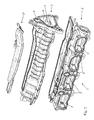
- FIGS. 1 to 5 show a distributor or intake manifold 1 consisting of a hollow body formed by the assembly of at least two constituent parts 2, 2 ', 2 "come from molding thermoplastic material (s) or metal.
- This hollow body comprises, on the one hand, a mixing / distribution or plenum chamber 3 with at least one feed opening 4 associated with a fixing plate 4 'or the like and, on the other hand, a plurality of tubes 5 connected to said chamber 3 and extending from the latter, said pipes 5 being provided or forming at their free ends a plate or flange 6 for fixing and sealing connection to the cylinder heads of an internal combustion engine.
- the pipes 5 may have valve receiving housings and their control shaft.
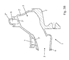
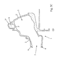
- said distributor 1 also comprises a separate or separated circuit 7, 8 for recovering and evacuating gases, in particular unburned combustion gases emanating from the casing and charged with oil or gas called "blow-by", this circuit 7, 8 being integrated in the structure of said distributor 1.
- the distributor 1 performs a second function in addition to its power function, namely a crankcase evacuation function.
- the integrated recovery and evacuation circuit further comprises, on the one hand, at least a first portion of recovery duct 7 having an inlet opening 7 'intended to be connected to an orifice of emptying present at a cylinder head, during assembly of the distributor 1 on the engine, and, secondly, a second portion of collection conduit and / or discharge 8 fluidly connected to the or each recovery portion 7 .
- the or each first portion of duct 7 is at least partially contiguous to a pipe 5, with which it shares a common wall portion 5 ', in particular near its inlet opening 7', and the second conduit portion 8 is at least partially contiguous to the mixing / distribution chamber 3, with which it shares a common wall portion 3 '.
- each portion 7 and 8 at least partially follows, preferably in all, the conformation and the configuration of the basic structure of the distributor 1, in particular the tubes 5 and the chamber 3, so as to generate a minimum of space additional, to make the most of the walls of the pipes 5 and the chamber 3 and to create the least possible parts protruding.
- the general shape of the distributor 1 is not substantially modified (with respect to a distributor 1 without circuit 7, 8) and its size is not substantially increased.
- the number of duct portions 7 and the location of the openings 7 'of these can be easily modified for the realization of a suitable distributor 1, without substantially changing the structure of the latter.
- each first portion of conduit 7 has a proximal portion of the second conduit portion 8, which is attached to the mixing / distribution chamber 3, with which it shares a common wall portion 3 ".
- the inlet opening 7 'of the or each recovery conduit portion 7 is located substantially in the connection plane of the tubing 5 to the cylinder heads, at the mounting and connection plate 6.
- the outlet opening 8 ' may be adjacent to one or to the supply opening (s) 4 of the mixing / distribution chamber 3 and is located substantially in the connection plane of this supply opening 4.
- the splitter 1 may have only one portion of conduit 7 if such a configuration is sufficient.
- the integrated circuit 7, 8 recovery and removal of unburned gases from the housing comprises at least two portions of recovery ducts 7 associated with two different pipes 5.
- the recovery pipe 7 and discharge 8 portions consist of tubular parts formed on the pipes 5 and the mixing chamber 3 / distribution, for example partially in one piece and partially by cooperation of the constituent parts 2, 2 ', 2 "forming said distributor or collector 1, these tubular portions or fragments of tubular parts being integral with these constituent parts 2 , 2 ', 2 ".
- the distributor 1 may consist of an assembly of three constituent parts 2, 2 'and 2 "in the form of separate parts integrally integrally molded, namely, a first part 2 comprising the tubes 5, a lower portion of the wall of the mixing / distribution chamber 3 and the tubular ends of the recovery pipe portions 7 defining the inlet openings 7 ', a second part 2' comprising the upper portion complementary to the wall of the mixing chamber 3 distribution, the complementary portion of the recovery pipe portions 7, a lower longitudinal portion of the portion discharge duct 8 and the connection interface of the feed opening 4 and a third portion 2 "forming the complementary upper longitudinal portion of the discharge portion 8.
- the distributor 1 may consist of an assembly of two constituent parts 2 and 2 'in the form of separate parts integrally integrally molded, namely on the one hand, a first part 2 comprising the tubes 5, the plate 6 fixing the pipes 5, a lower portion of the wall of the mixing / distribution chamber 3, the lower portions of the recovery pipe portions 7 and their tubular ends defining the inlet openings 7 'and, on the other hand, a second part 2 'comprising the upper complementary portion of the wall of the mixing / distribution chamber 3, the supply opening 4 thereof and its fixing plate 4', the exhaust duct portion 8, the complementary upper parts of recovery ducts 7.
- the constituent parts 2, 2 'and 2 " are molded parts made of thermoplastic material and their assembly is performed by vibration welding.
- the invention also relates to a motor vehicle with an internal combustion engine, characterized in that its air / fuel mixture supply system comprises an intake distributor as described above, the internal combustion engine comprising at least one gas evacuation orifice in the housing, located (s) near at least one injection port of the air / fuel mixture of a cylinder head.
Landscapes
- Engineering & Computer Science (AREA)
- Mechanical Engineering (AREA)
- General Engineering & Computer Science (AREA)
- Chemical & Material Sciences (AREA)
- Combustion & Propulsion (AREA)
- Manufacturing & Machinery (AREA)
- Lubrication Details And Ventilation Of Internal Combustion Engines (AREA)
Applications Claiming Priority (1)
| Application Number | Priority Date | Filing Date | Title |
|---|---|---|---|
| FR0956042A FR2949823B1 (fr) | 2009-09-04 | 2009-09-04 | Repartiteur integrant un circuit d'evacuation des gaz du carter et vehicule comportant un tel repartiteur |
Publications (2)
| Publication Number | Publication Date |
|---|---|
| EP2299100A1 true EP2299100A1 (de) | 2011-03-23 |
| EP2299100B1 EP2299100B1 (de) | 2012-10-24 |
Family
ID=42060548
Family Applications (1)
| Application Number | Title | Priority Date | Filing Date |
|---|---|---|---|
| EP20100305957 Active EP2299100B1 (de) | 2009-09-04 | 2010-09-06 | Saugrohr mit integrierter Kurbelgehäuseentlüftung und Fahrzeug mit einem solchen Saugrohr |
Country Status (2)
| Country | Link |
|---|---|
| EP (1) | EP2299100B1 (de) |
| FR (1) | FR2949823B1 (de) |
Cited By (1)
| Publication number | Priority date | Publication date | Assignee | Title |
|---|---|---|---|---|
| EP3043061A1 (de) * | 2015-01-08 | 2016-07-13 | Aisin Seiki Kabushiki Kaisha | Ansaugsystem für verbrennungsmotoren |
Citations (9)
| Publication number | Priority date | Publication date | Assignee | Title |
|---|---|---|---|---|
| US4602607A (en) * | 1985-02-25 | 1986-07-29 | General Motors Corporation | Internal crankcase ventilation system with easily accessible PCV valve |
| EP0454512A1 (de) | 1990-04-26 | 1991-10-30 | Automobiles Peugeot | Reinigungs- und Rezirkulationseinrichtung für die Durchblasgase einer Brennkraftmaschine und Brennkraftmaschine ausgerüstet mit dieser Einrichtung |
| DE10320493A1 (de) * | 2003-05-08 | 2004-12-02 | Volkswagen Ag | Brennkraftmaschine mit Kurbelgehäuseentlüftung |
| DE10330493A1 (de) | 2003-07-05 | 2005-02-10 | Hyperstone Ag | Verfahren zur Verwaltung von Speicherinformationen |
| DE102004012160A1 (de) * | 2004-03-12 | 2005-09-29 | Adam Opel Ag | Kurbelgehäuseentlüftung |
| EP1801369A1 (de) * | 2005-12-22 | 2007-06-27 | GM Global Technology Operations, Inc. | Saugrohr-Zylinderkopfanordnung |
| DE102006038831A1 (de) * | 2006-08-18 | 2008-02-21 | Volkswagen Ag | Brennkraftmaschine mit Rückführung von Blow-By-Gasen |
| EP2038520A1 (de) | 2006-05-09 | 2009-03-25 | Dayco Fluid Technologies S.p.A. | Durchblasgasabscheidervorrichtung für einen verbrennungsmotor eines kraftfahrzeugs |
| EP2050935A2 (de) | 2007-10-19 | 2009-04-22 | Nissan Motor Co., Ltd. | Blowby-Gas-Verarbeitungsvorrichtung für Verbrennungsmotor |
Family Cites Families (4)
| Publication number | Priority date | Publication date | Assignee | Title |
|---|---|---|---|---|
| DE3918785A1 (de) * | 1989-06-08 | 1990-12-13 | Bayerische Motoren Werke Ag | Sauganlage einer brennkraftmaschine |
| DE10105555B4 (de) * | 2001-02-06 | 2016-02-25 | Volkswagen Ag | Entlüftungsvorrichtung für ölbeladene Gase einer Brennkraftmaschine |
| FR2847307B1 (fr) * | 2002-11-20 | 2007-03-02 | Mark Iv Systemes Moteurs Sa | Collecteur d'admission en deux parties |
| KR20050047218A (ko) * | 2003-11-17 | 2005-05-20 | 현대자동차주식회사 | 내연기관 엔진의 포지티브 크랭크케이스 벤틸레이션 시스템 |
-
2009
- 2009-09-04 FR FR0956042A patent/FR2949823B1/fr not_active Expired - Fee Related
-
2010
- 2010-09-06 EP EP20100305957 patent/EP2299100B1/de active Active
Patent Citations (9)
| Publication number | Priority date | Publication date | Assignee | Title |
|---|---|---|---|---|
| US4602607A (en) * | 1985-02-25 | 1986-07-29 | General Motors Corporation | Internal crankcase ventilation system with easily accessible PCV valve |
| EP0454512A1 (de) | 1990-04-26 | 1991-10-30 | Automobiles Peugeot | Reinigungs- und Rezirkulationseinrichtung für die Durchblasgase einer Brennkraftmaschine und Brennkraftmaschine ausgerüstet mit dieser Einrichtung |
| DE10320493A1 (de) * | 2003-05-08 | 2004-12-02 | Volkswagen Ag | Brennkraftmaschine mit Kurbelgehäuseentlüftung |
| DE10330493A1 (de) | 2003-07-05 | 2005-02-10 | Hyperstone Ag | Verfahren zur Verwaltung von Speicherinformationen |
| DE102004012160A1 (de) * | 2004-03-12 | 2005-09-29 | Adam Opel Ag | Kurbelgehäuseentlüftung |
| EP1801369A1 (de) * | 2005-12-22 | 2007-06-27 | GM Global Technology Operations, Inc. | Saugrohr-Zylinderkopfanordnung |
| EP2038520A1 (de) | 2006-05-09 | 2009-03-25 | Dayco Fluid Technologies S.p.A. | Durchblasgasabscheidervorrichtung für einen verbrennungsmotor eines kraftfahrzeugs |
| DE102006038831A1 (de) * | 2006-08-18 | 2008-02-21 | Volkswagen Ag | Brennkraftmaschine mit Rückführung von Blow-By-Gasen |
| EP2050935A2 (de) | 2007-10-19 | 2009-04-22 | Nissan Motor Co., Ltd. | Blowby-Gas-Verarbeitungsvorrichtung für Verbrennungsmotor |
Cited By (2)
| Publication number | Priority date | Publication date | Assignee | Title |
|---|---|---|---|---|
| EP3043061A1 (de) * | 2015-01-08 | 2016-07-13 | Aisin Seiki Kabushiki Kaisha | Ansaugsystem für verbrennungsmotoren |
| CN105781821A (zh) * | 2015-01-08 | 2016-07-20 | 爱信精机株式会社 | 内燃发动机的进气系统 |
Also Published As
| Publication number | Publication date |
|---|---|
| FR2949823A1 (fr) | 2011-03-11 |
| FR2949823B1 (fr) | 2013-05-10 |
| EP2299100B1 (de) | 2012-10-24 |
Similar Documents
| Publication | Publication Date | Title |
|---|---|---|
| FR2705997A1 (fr) | Dispositif de tuyaux d'admission pour un moteur à combustion interne ayant des tuyaux d'admission arqués individuellement pour chaque cylindre. | |
| FR2660017A1 (fr) | Dispositif d'admission et de deshuilage des gaz dans un moteur a combustion interne et moteur equipe de ce dispositif. | |
| FR2926789A1 (fr) | Nacelle pour turboreacteur | |
| FR2518645A1 (fr) | Moteur a pistons et a combustion interne suralimente par des turbocompresseurs a gaz d'echappement | |
| EP2299100B1 (de) | Saugrohr mit integrierter Kurbelgehäuseentlüftung und Fahrzeug mit einem solchen Saugrohr | |
| FR2809772A1 (fr) | Collecteur d'admission perfectionne pour moteur hors bord | |
| EP1831535A1 (de) | Vorrichtung zum einschliessen von verbrennungsluft eines verbrennungsmotors | |
| FR2765631A1 (fr) | Installation d'aspiration d'air pour un moteur a combustion interne | |
| EP0846223B1 (de) | Ansaugkrümmer für brennkraftmaschine | |
| EP0470874A1 (de) | Brennkraftmaschine mit Lufteinlasseinrichtung integriert in einem Zylinderkopf | |
| EP2649283B1 (de) | Vorrichtung zur kanalisierung eines zufuhrgasstroms für einen verbrennungsmotor | |
| EP3839239B1 (de) | Verbrennungsmotor mit ansaugkrümmer mit integrierter kurbelgehäuseentlüftungsgaserücklaufleitung | |
| FR2932847A1 (fr) | Moteur a combustion interne equipe d'un turbocompresseur de suralimentation. | |
| EP2497936B1 (de) | Multifunkionsansaugleitung für einen Dieselmotor | |
| EP0768462B1 (de) | Kreisringförmiger Diffusor für Abgasrückführung für Brennkraftmaschine | |
| EP1795733B1 (de) | Schalldämpfer zur Verringerung von Luftgeräuschen, insbesondre für interne Brennkraftmaschinen | |
| EP3877632B1 (de) | Blow-by-diffusionsvorrichtung am einlass eines zylinderkopfes | |
| EP1215390A1 (de) | Brennstoffzufuhrvorrichtung für eine Brennkraftmaschine und Brennstoffilter für eine solche Vorrichtung | |
| FR3082241A1 (fr) | Repartiteur d'admission pour moteur thermique avec dispositif de melange de gaz recircules | |
| EP4069951B1 (de) | Öldekanter mit einer frischluftkammer | |
| FR2926852A1 (fr) | Ensemble moteur pour un vehicule automobile et vehicule automobile comprenant un tel ensemble moteur | |
| EP3999731B1 (de) | Verteiler mit halbintegrierter strömungstrennung | |
| EP3480439A1 (de) | Luftzufuhrkreislauf für motor mit gesteuerter zündung mit einer im zylinderkopf integrierten druckkammer | |
| FR2905422A1 (fr) | Systeme de refroidissement d'un vehicule automobile | |
| FR3098866A1 (fr) | Repartiteur avec séparation des flux et conduits intégrés |
Legal Events
| Date | Code | Title | Description |
|---|---|---|---|
| PUAI | Public reference made under article 153(3) epc to a published international application that has entered the european phase |
Free format text: ORIGINAL CODE: 0009012 |
|
| AK | Designated contracting states |
Kind code of ref document: A1 Designated state(s): AL AT BE BG CH CY CZ DE DK EE ES FI FR GB GR HR HU IE IS IT LI LT LU LV MC MK MT NL NO PL PT RO SE SI SK SM TR |
|
| AX | Request for extension of the european patent |
Extension state: BA ME RS |
|
| 17P | Request for examination filed |
Effective date: 20110922 |
|
| RIC1 | Information provided on ipc code assigned before grant |
Ipc: F02M 25/06 20060101ALN20120423BHEP Ipc: F02M 35/104 20060101AFI20120423BHEP Ipc: F02M 35/10 20060101ALN20120423BHEP Ipc: F01M 13/00 20060101ALI20120423BHEP |
|
| GRAP | Despatch of communication of intention to grant a patent |
Free format text: ORIGINAL CODE: EPIDOSNIGR1 |
|
| RIC1 | Information provided on ipc code assigned before grant |
Ipc: F02M 35/10 20060101ALN20120516BHEP Ipc: F01M 13/00 20060101ALI20120516BHEP Ipc: F02M 35/104 20060101AFI20120516BHEP Ipc: F02M 25/06 20060101ALN20120516BHEP |
|
| GRAS | Grant fee paid |
Free format text: ORIGINAL CODE: EPIDOSNIGR3 |
|
| GRAA | (expected) grant |
Free format text: ORIGINAL CODE: 0009210 |
|
| RAP1 | Party data changed (applicant data changed or rights of an application transferred) |
Owner name: SYSTEMES MOTEURS |
|
| AK | Designated contracting states |
Kind code of ref document: B1 Designated state(s): AL AT BE BG CH CY CZ DE DK EE ES FI FR GB GR HR HU IE IS IT LI LT LU LV MC MK MT NL NO PL PT RO SE SI SK SM TR |
|
| REG | Reference to a national code |
Ref country code: GB Ref legal event code: FG4D Free format text: NOT ENGLISH |
|
| REG | Reference to a national code |
Ref country code: CH Ref legal event code: EP |
|
| REG | Reference to a national code |
Ref country code: AT Ref legal event code: REF Ref document number: 581096 Country of ref document: AT Kind code of ref document: T Effective date: 20121115 |
|
| REG | Reference to a national code |
Ref country code: IE Ref legal event code: FG4D Free format text: LANGUAGE OF EP DOCUMENT: FRENCH |
|
| REG | Reference to a national code |
Ref country code: DE Ref legal event code: R096 Ref document number: 602010003342 Country of ref document: DE Effective date: 20121220 |
|
| REG | Reference to a national code |
Ref country code: AT Ref legal event code: MK05 Ref document number: 581096 Country of ref document: AT Kind code of ref document: T Effective date: 20121024 |
|
| REG | Reference to a national code |
Ref country code: NL Ref legal event code: VDEP Effective date: 20121024 |
|
| PG25 | Lapsed in a contracting state [announced via postgrant information from national office to epo] |
Ref country code: NO Free format text: LAPSE BECAUSE OF FAILURE TO SUBMIT A TRANSLATION OF THE DESCRIPTION OR TO PAY THE FEE WITHIN THE PRESCRIBED TIME-LIMIT Effective date: 20130124 Ref country code: HR Free format text: LAPSE BECAUSE OF FAILURE TO SUBMIT A TRANSLATION OF THE DESCRIPTION OR TO PAY THE FEE WITHIN THE PRESCRIBED TIME-LIMIT Effective date: 20121024 Ref country code: SE Free format text: LAPSE BECAUSE OF FAILURE TO SUBMIT A TRANSLATION OF THE DESCRIPTION OR TO PAY THE FEE WITHIN THE PRESCRIBED TIME-LIMIT Effective date: 20121024 Ref country code: IS Free format text: LAPSE BECAUSE OF FAILURE TO SUBMIT A TRANSLATION OF THE DESCRIPTION OR TO PAY THE FEE WITHIN THE PRESCRIBED TIME-LIMIT Effective date: 20130224 Ref country code: ES Free format text: LAPSE BECAUSE OF FAILURE TO SUBMIT A TRANSLATION OF THE DESCRIPTION OR TO PAY THE FEE WITHIN THE PRESCRIBED TIME-LIMIT Effective date: 20130204 Ref country code: NL Free format text: LAPSE BECAUSE OF FAILURE TO SUBMIT A TRANSLATION OF THE DESCRIPTION OR TO PAY THE FEE WITHIN THE PRESCRIBED TIME-LIMIT Effective date: 20121024 Ref country code: FI Free format text: LAPSE BECAUSE OF FAILURE TO SUBMIT A TRANSLATION OF THE DESCRIPTION OR TO PAY THE FEE WITHIN THE PRESCRIBED TIME-LIMIT Effective date: 20121024 |
|
| PG25 | Lapsed in a contracting state [announced via postgrant information from national office to epo] |
Ref country code: LV Free format text: LAPSE BECAUSE OF FAILURE TO SUBMIT A TRANSLATION OF THE DESCRIPTION OR TO PAY THE FEE WITHIN THE PRESCRIBED TIME-LIMIT Effective date: 20121024 Ref country code: SI Free format text: LAPSE BECAUSE OF FAILURE TO SUBMIT A TRANSLATION OF THE DESCRIPTION OR TO PAY THE FEE WITHIN THE PRESCRIBED TIME-LIMIT Effective date: 20121024 Ref country code: PT Free format text: LAPSE BECAUSE OF FAILURE TO SUBMIT A TRANSLATION OF THE DESCRIPTION OR TO PAY THE FEE WITHIN THE PRESCRIBED TIME-LIMIT Effective date: 20130225 Ref country code: GR Free format text: LAPSE BECAUSE OF FAILURE TO SUBMIT A TRANSLATION OF THE DESCRIPTION OR TO PAY THE FEE WITHIN THE PRESCRIBED TIME-LIMIT Effective date: 20130125 Ref country code: PL Free format text: LAPSE BECAUSE OF FAILURE TO SUBMIT A TRANSLATION OF THE DESCRIPTION OR TO PAY THE FEE WITHIN THE PRESCRIBED TIME-LIMIT Effective date: 20121024 |
|
| PG25 | Lapsed in a contracting state [announced via postgrant information from national office to epo] |
Ref country code: AT Free format text: LAPSE BECAUSE OF FAILURE TO SUBMIT A TRANSLATION OF THE DESCRIPTION OR TO PAY THE FEE WITHIN THE PRESCRIBED TIME-LIMIT Effective date: 20121024 |
|
| PG25 | Lapsed in a contracting state [announced via postgrant information from national office to epo] |
Ref country code: BG Free format text: LAPSE BECAUSE OF FAILURE TO SUBMIT A TRANSLATION OF THE DESCRIPTION OR TO PAY THE FEE WITHIN THE PRESCRIBED TIME-LIMIT Effective date: 20130124 Ref country code: CZ Free format text: LAPSE BECAUSE OF FAILURE TO SUBMIT A TRANSLATION OF THE DESCRIPTION OR TO PAY THE FEE WITHIN THE PRESCRIBED TIME-LIMIT Effective date: 20121024 Ref country code: SK Free format text: LAPSE BECAUSE OF FAILURE TO SUBMIT A TRANSLATION OF THE DESCRIPTION OR TO PAY THE FEE WITHIN THE PRESCRIBED TIME-LIMIT Effective date: 20121024 Ref country code: EE Free format text: LAPSE BECAUSE OF FAILURE TO SUBMIT A TRANSLATION OF THE DESCRIPTION OR TO PAY THE FEE WITHIN THE PRESCRIBED TIME-LIMIT Effective date: 20121024 Ref country code: DK Free format text: LAPSE BECAUSE OF FAILURE TO SUBMIT A TRANSLATION OF THE DESCRIPTION OR TO PAY THE FEE WITHIN THE PRESCRIBED TIME-LIMIT Effective date: 20121024 |
|
| PG25 | Lapsed in a contracting state [announced via postgrant information from national office to epo] |
Ref country code: RO Free format text: LAPSE BECAUSE OF FAILURE TO SUBMIT A TRANSLATION OF THE DESCRIPTION OR TO PAY THE FEE WITHIN THE PRESCRIBED TIME-LIMIT Effective date: 20121024 Ref country code: IT Free format text: LAPSE BECAUSE OF FAILURE TO SUBMIT A TRANSLATION OF THE DESCRIPTION OR TO PAY THE FEE WITHIN THE PRESCRIBED TIME-LIMIT Effective date: 20121024 |
|
| PLBE | No opposition filed within time limit |
Free format text: ORIGINAL CODE: 0009261 |
|
| STAA | Information on the status of an ep patent application or granted ep patent |
Free format text: STATUS: NO OPPOSITION FILED WITHIN TIME LIMIT |
|
| 26N | No opposition filed |
Effective date: 20130725 |
|
| REG | Reference to a national code |
Ref country code: DE Ref legal event code: R097 Ref document number: 602010003342 Country of ref document: DE Effective date: 20130725 |
|
| PG25 | Lapsed in a contracting state [announced via postgrant information from national office to epo] |
Ref country code: CY Free format text: LAPSE BECAUSE OF FAILURE TO SUBMIT A TRANSLATION OF THE DESCRIPTION OR TO PAY THE FEE WITHIN THE PRESCRIBED TIME-LIMIT Effective date: 20121024 |
|
| BERE | Be: lapsed |
Owner name: SYSTEMES MOTEURS Effective date: 20130930 |
|
| PG25 | Lapsed in a contracting state [announced via postgrant information from national office to epo] |
Ref country code: MC Free format text: LAPSE BECAUSE OF FAILURE TO SUBMIT A TRANSLATION OF THE DESCRIPTION OR TO PAY THE FEE WITHIN THE PRESCRIBED TIME-LIMIT Effective date: 20121024 |
|
| REG | Reference to a national code |
Ref country code: IE Ref legal event code: MM4A |
|
| PG25 | Lapsed in a contracting state [announced via postgrant information from national office to epo] |
Ref country code: IE Free format text: LAPSE BECAUSE OF NON-PAYMENT OF DUE FEES Effective date: 20130906 Ref country code: LT Free format text: LAPSE BECAUSE OF FAILURE TO SUBMIT A TRANSLATION OF THE DESCRIPTION OR TO PAY THE FEE WITHIN THE PRESCRIBED TIME-LIMIT Effective date: 20121024 Ref country code: BE Free format text: LAPSE BECAUSE OF NON-PAYMENT OF DUE FEES Effective date: 20130930 |
|
| REG | Reference to a national code |
Ref country code: CH Ref legal event code: PL |
|
| GBPC | Gb: european patent ceased through non-payment of renewal fee |
Effective date: 20140906 |
|
| PG25 | Lapsed in a contracting state [announced via postgrant information from national office to epo] |
Ref country code: SM Free format text: LAPSE BECAUSE OF FAILURE TO SUBMIT A TRANSLATION OF THE DESCRIPTION OR TO PAY THE FEE WITHIN THE PRESCRIBED TIME-LIMIT Effective date: 20121024 |
|
| PG25 | Lapsed in a contracting state [announced via postgrant information from national office to epo] |
Ref country code: TR Free format text: LAPSE BECAUSE OF FAILURE TO SUBMIT A TRANSLATION OF THE DESCRIPTION OR TO PAY THE FEE WITHIN THE PRESCRIBED TIME-LIMIT Effective date: 20121024 Ref country code: MT Free format text: LAPSE BECAUSE OF FAILURE TO SUBMIT A TRANSLATION OF THE DESCRIPTION OR TO PAY THE FEE WITHIN THE PRESCRIBED TIME-LIMIT Effective date: 20121024 |
|
| PG25 | Lapsed in a contracting state [announced via postgrant information from national office to epo] |
Ref country code: HU Free format text: LAPSE BECAUSE OF FAILURE TO SUBMIT A TRANSLATION OF THE DESCRIPTION OR TO PAY THE FEE WITHIN THE PRESCRIBED TIME-LIMIT; INVALID AB INITIO Effective date: 20100906 Ref country code: LI Free format text: LAPSE BECAUSE OF NON-PAYMENT OF DUE FEES Effective date: 20140930 Ref country code: MK Free format text: LAPSE BECAUSE OF FAILURE TO SUBMIT A TRANSLATION OF THE DESCRIPTION OR TO PAY THE FEE WITHIN THE PRESCRIBED TIME-LIMIT Effective date: 20121024 Ref country code: GB Free format text: LAPSE BECAUSE OF NON-PAYMENT OF DUE FEES Effective date: 20140906 Ref country code: CH Free format text: LAPSE BECAUSE OF NON-PAYMENT OF DUE FEES Effective date: 20140930 Ref country code: LU Free format text: LAPSE BECAUSE OF NON-PAYMENT OF DUE FEES Effective date: 20130906 |
|
| REG | Reference to a national code |
Ref country code: FR Ref legal event code: PLFP Year of fee payment: 7 |
|
| REG | Reference to a national code |
Ref country code: FR Ref legal event code: PLFP Year of fee payment: 8 |
|
| REG | Reference to a national code |
Ref country code: FR Ref legal event code: PLFP Year of fee payment: 9 |
|
| PG25 | Lapsed in a contracting state [announced via postgrant information from national office to epo] |
Ref country code: AL Free format text: LAPSE BECAUSE OF FAILURE TO SUBMIT A TRANSLATION OF THE DESCRIPTION OR TO PAY THE FEE WITHIN THE PRESCRIBED TIME-LIMIT Effective date: 20121024 |
|
| P01 | Opt-out of the competence of the unified patent court (upc) registered |
Effective date: 20230620 |
|
| PGFP | Annual fee paid to national office [announced via postgrant information from national office to epo] |
Ref country code: DE Payment date: 20240918 Year of fee payment: 15 |
|
| PGFP | Annual fee paid to national office [announced via postgrant information from national office to epo] |
Ref country code: FR Payment date: 20240925 Year of fee payment: 15 |