EP0455097B1 - Schiffssteuerungsvorrichtung - Google Patents
Schiffssteuerungsvorrichtung Download PDFInfo
- Publication number
- EP0455097B1 EP0455097B1 EP91106483A EP91106483A EP0455097B1 EP 0455097 B1 EP0455097 B1 EP 0455097B1 EP 91106483 A EP91106483 A EP 91106483A EP 91106483 A EP91106483 A EP 91106483A EP 0455097 B1 EP0455097 B1 EP 0455097B1
- Authority
- EP
- European Patent Office
- Prior art keywords
- coupling means
- driven member
- control system
- boat
- driving member
- Prior art date
- Legal status (The legal status is an assumption and is not a legal conclusion. Google has not performed a legal analysis and makes no representation as to the accuracy of the status listed.)
- Expired - Lifetime
Links
Images



Classifications
-
- G—PHYSICS
- G05—CONTROLLING; REGULATING
- G05G—CONTROL DEVICES OR SYSTEMS INSOFAR AS CHARACTERISED BY MECHANICAL FEATURES ONLY
- G05G5/00—Means for preventing, limiting or returning the movements of parts of a control mechanism, e.g. locking controlling member
- G05G5/12—Means for preventing, limiting or returning the movements of parts of a control mechanism, e.g. locking controlling member for holding members in an indefinite number of positions, e.g. by a toothed quadrant
- G05G5/14—Means for preventing, limiting or returning the movements of parts of a control mechanism, e.g. locking controlling member for holding members in an indefinite number of positions, e.g. by a toothed quadrant by locking a member with respect to a fixed quadrant, rod, or the like
- G05G5/16—Means for preventing, limiting or returning the movements of parts of a control mechanism, e.g. locking controlling member for holding members in an indefinite number of positions, e.g. by a toothed quadrant by locking a member with respect to a fixed quadrant, rod, or the like by friction
-
- B—PERFORMING OPERATIONS; TRANSPORTING
- B63—SHIPS OR OTHER WATERBORNE VESSELS; RELATED EQUIPMENT
- B63H—MARINE PROPULSION OR STEERING
- B63H21/00—Use of propulsion power plant or units on vessels
- B63H21/21—Control means for engine or transmission, specially adapted for use on marine vessels
- B63H21/213—Levers or the like for controlling the engine or the transmission, e.g. single hand control levers
Definitions
- This invention relates to helm, throttle and directional controls for such small craft as outboard, inboard, and inboard/outboard powered boats and in particular concerns a safety arrangement which fits between a driving member and a driven member in helm, throttle and directional controls.
- the driving member may be a control drive shaft connected to the steering wheel of a boat
- the driven member may be a driven shaft coupled to a control cable for the boat's steering device.
- the driving member may also be a control drive shaft connected to a throttle control lever and/or a reverse control lever for the boat's powerplant, and the driven member may be a driven shaft coupled to a throttle control cable and/or a reverse gear control cable.
- Powerplant controls also require that no undesired change be applied fortuitously to any pre-selected settings.
- a most widely employed method of preventing undesired and fortuitous changes to the setting of the driven member has been that of braking the rotational movement of the driving member as by means of a slip clutch between the driving and driven members.
- this tends to make the driving member stiffer and tiring to operate, and anyhow cannot provide failsafe unalterability of the setting where, for example, the forces acting on the driven member are large ones.
- FIG. 1 shown at 1 is the steering wheel of the helm of a boat, e.g. a motor boat.
- the steering wheel drive shaft 2 penetrates a box 3 accommodating a unit whereby the helm control cable 4 can be operated.
- this cable control unit may be any suitable type to convert the rotary movement of the steering wheel 1 into a linear movement of the cable 4, and may either be of the rack-and-pinion, or chain-and-sprocket, or other comparable types.
- the safety arrangement would be interposed between the shaft 2 and the input end of the cable 4 control unit.
- a stationary pin which may be affixed to the bottom of the box 3, for example. Tightly wound around this pin 5 is a cylindrical coil spring 6 having its ends 106 and 206 bent to project radially outwards, from diametrically opposite positions of the spring, as shown best in Figure 4. That end of the shaft 2 which extends into the box 3 is shaped as a half-cup 7, so as to embrace the pin 5 and the spring 6 wound thereon with some radial and axial clearance, and extends circumferentially around the pin 5 through an angle of 180°-2 ⁇ , as shown best in Figure 4.
- the radius for the half-cup shape 7 should be such that the latter engages, as the shaft 2 is rotated, with ends 106 and 206, respectively, of the spring 6, for purposes to be explained.
- the half-cup shape 7 is also formed, at the base thereof where it does not interfere with said ends of the spring 6, with two teeth or dogs 107, 207 which extend circumferentially and symmetrically from either sides through an angle alpha ( ⁇ ), thereby the half-cup shape will extend through 180° at the. location of said teeth.
- Referenced 8 is the driven shaft for operating the steering arrangement.
- this shaft 8 is a tubular shaft mounted for free rotation on the shaft 2 concentrically therewith.
- Said shaft 8 is terminated with a half-cup shape 9 having the same radius as the shape 7 and extending around the pin 5 through an angle of 180°-2 ⁇ .
- a pinion gear 10 Keyed on the other end of shaft 8 is a pinion gear 10 which may either mesh directly with the cable 4 where in helical form as shown in Figure 3, or with a rack connected to the cable 4.
- Shaft 2 forms the driving member for the helm system shown and shaft 8 its driven member.
- the half-cup shape 7 will be turned accordingly in that direction through the shaft 2 of the wheel 1.
- shape 7 will abut against the end 106 of the spring 6 and urge it in the opposite direction from the winding direction of the spring 6 around the pin 5.
- Figures 5 and 6 show a safety arrangement quite similar to that in Figures 2, 3 and 4, and similar or corresponding parts of this arrangement will be referenced, therefore, as in the previously described embodiment.
- the spring 6 is disposed with radial clearance around the two half-cup shapes 7 and 9, respectively unitary with the drive shaft 2 and the driven shaft 8, and is urged against a concentrical bush 5′ affixed to the helm box 3 in any suitable manner.
- the ends 106, 206 of the spring 6 are bent radially inwards so as to intervene between the half-cup shapes 7 and 9.
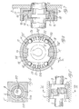
- Figures 7 and 8 show a further embodiment of the safety arrangement of the boat control system according to the invention.
- the drive shaft is terminated with two radial arms 11 and 12 projecting from radially opposite positions. Connected to those arms 11 and 12 are two cylinder segment elements 13 and 14 which extend over an arc of about 90° and are each provided with a tooth or dog 15 and 16, respectively, centrally thereon, the teeth or dogs extending radially toward the center.
- the two segments 13 and 14 are accommodated inside a cylindrical case 17 attached to the box 3 in a freely rotatable manner with a small radial clearance.
- an element 18 Located within the case 17, between the segments 13 and 14, is an element 18 connected to the driven shaft 8.
- This element 18 is formed, at diametrically opposite locations thereon, with two notches 118, 118′ engaging the teeth 15 and 16 with a backlash 2 ⁇ . It also has, at diametrically opposite Locations orthogonal to the notches 118, 118′, two substantially straight surfaces 218, 218′. Two spaces 23 and 24, bound by the surfaces 218, 218′, the inner wall of the cylindrical case 17, and the ends of the cylinder segments 13 and 14, accommodate two ball pairs 19, 19′ and 20, 20′ which are constantly biased in opposite directions toward the ends of the segments 13 and 14 by two springs 21 and 22. The diameters of the balls 19, 19′ and 20, 20′ are sized such that, in their rest position, the balls will wedge between the ends of the camming surfaces 218, 218′ and the inner wall of the case 17.
- any attempt at rotating the driven shaft 8 in either direction would be defeated by the balls 19, 19′ and 20, 20′ wedging themselves between the surfaces 218, 218′ and the inner wall of the case 17.
- a rotation of the drive shaft 2 will drive the elements 13 and 14 through a fraction of their stroke equivalent to the backlash angle alpha, thereby the ends of said elements are caused to act on two diametrically opposed balls, e.g. balls 19′ and 20 when the shaft 2 is turned counterclockwise, and pry them out of the angle between the wall of the case 17 and the corresponding surface 218, 218′ of element 18, thus enabling the shaft 2 to transfer rotary motion to the element 18 through the teeth 15 and 16, and thence to the driven shaft 8.
- the safety arrangement will be restored automatically to its locked condition by the action from the springs 21 and 22.
- a remote control box 25 of the single lever 26 type as commonly employed to control the speed and direction of boats powered with outboard motors, or inboard engines, or inboard/outboard units equipped with hydraulically operated reverse gears.
- control Lever 26 is keyed to one end of the drive shaft 2 relating to the safety arrangement shown in Figures 2, 3 and 4.
- the safety arrangement could be obviously embodied alternatively as shown in Figures 5 to 8.
- FIG 11 Depicted in Figure 11 is a situation where a helmsman, shown at 30, has fallen overboard from a water vehicle, shown at 31, having its helm or steering system equipped with a safety arrangement of the boat control system according to the invention.
- the boat 31, presently with no one at the helm will keep running in the same (straight, in the example) direction of its course before the helmsman fell overboard since the steering device 32 of the boat is locked by the safety arrangement in the same position as before the incident. Absent the safety arrangement, the water flow around the steering device 32 would gradually bring the steering device to a position of tightest turn of the boat, thereby the boat would close in toward the man in the water along a spiral course and endanger his safety.
Landscapes
- Engineering & Computer Science (AREA)
- Physics & Mathematics (AREA)
- General Physics & Mathematics (AREA)
- Automation & Control Theory (AREA)
- Chemical & Material Sciences (AREA)
- Combustion & Propulsion (AREA)
- Mechanical Engineering (AREA)
- Ocean & Marine Engineering (AREA)
- Mechanical Control Devices (AREA)
- Control Of Vehicle Engines Or Engines For Specific Uses (AREA)
- Toys (AREA)
- Output Control And Ontrol Of Special Type Engine (AREA)
Claims (15)
- Bootssteuerungsvorrichtung, die ein antreibendes Element (2) und ein angetriebenes Element (8) umfaßt, die drehbar durch eine mechanische Einweg-Kupplungseinrichtung verbunden sind, wobei das angetriebene Element (8) durch eine elastische Kraft konstant in einer arretierten Position gehalten wird, und Lösung automatisch ausgeführt wird, indem das antreibende Element (2) gegen die elastische Kraft bewegt wird, um Bewegung von dem antreibenden Element (2) auf das angetriebene Element (8) zu übertragen, dadurch gekennzeichnet, daß zwei im wesentlichen halbzylindrische Kupplungseinrichtungen (7, 9) vorhanden sind, wobei eine (7) von dem antreibenden Element (2) getragen wird, und die andere (9) von dem angetriebenen Element (8) getragen wird, wobei die Kupplungseinrichtungen (7, 9) Profilabschnitte umfassen, die im wesentlichen mit einem Betrag an Spiel aneinanderpassen, und eine einzelne Spiralfeder (6) vorhanden ist, die koaxial zu den kupplungseinrichtungen (7, 9) und in Reibungskontakt mit einem stationären Abschnitt (5; 5′) der Vorrichtung ist, wobei die Profilabschnitte der anderen Kupplungseinrichtung (9) an Teilen anliegen, die mit den Enden der Spiralfeder (6) verbunden sind, um Drehung des angetriebenen Elementes (8) zu verhindern, wobei die Profilabschnitte der einen Kupplungseinrichtung (7) mit den Teilen zusammenwirken, die mit den Enden der Spiralfeder (6) verbunden sind, um den Reibungskontakt der Spiralfeder (6) mit dem stationären Abschnitt (5; 5′) zu verringern oder aufzuheben und das angetriebene Element (8) zu entarretieren, wobei die eine Kupplungseinrichtung (7) die andere Kupplungseinrichtung (9) drehend mitführt, wenn das angetriebene Element (8) entarretiert ist, um Bewegung von dem antreibenden Element (2) auf das angetriebene Element (8) zu übertragen.
- Bootsseuerungsvorrichtung nach Anspruch 1, wobei die Spiralfeder (6) zusammengezogen wird, indem sie fest um ein Element gewunden wird, das aus einem Zapfen (5) des stationären Abschnitts der Vorrichtung besteht, und wobei die Enden (106, 206) der Sprialfeder (6) radial nach außen gebogen sind, so daß sie an den Profilabschnitten der anderen Kupplungseinrichtung (9) anliegen und mit den Profilabschnitten der einen Kupplungseinrichtung (7) in Eingriff sind.
- Bootssteuerungsvorrichtung nach Anspruch 1, wobei die Spiralfeder (6) in Kupplungseingriff mit den Wänden eines Elementes zusammengedrückt wird, das aus einer umschließenden Buchse (5′) des stationären Abschnitts der Vorrichtung besteht, und wobei die Enden (106, 206) der Spiralfeder (6) radial nach innen gebogen sind, so daß sie an den Profilabschnitten der anderen Kupplungseinrichtung (9) anliegen und mit den Profilabechnitten der einen Kupplungseinrichtung (7) in Eingriff sind.
- Bootssteuerungsvorrichtung nach Anspruch 2 oder 3, wobei die Spiralfeder (6) zylindrisch ist und an dem Element (5; 5′) des stationären Abschnitts der Vorrichtung so angebracht ist, daß die Wirkung der Profilabschnitte der anderen Kupplungseinrichtung (9) auf die Spiralfederenden (106, 206) den Reibungskontakt mit dem Element (5; 5′) des stationären Abschnitts verstärkt, während die Wirkung des Profilabschnitte der einen Kupplungseinrichtung (7) auf die Federenden (106, 206) den Reibungskontakt mit dem Element (5; 5′) des stationären Abschnitts verringert oder aufhebt.
- Bootssteuerungsvorrichtung nach Anspruch 4, wobei das antreibende Element und das angetriebene Element eine Antriebswelle (2) bzw. eine Abtriebswelle (8) sind, die koaxial zueinander sind, und wobei die beiden Kupplungseinrichtungen zwei Halbschalenformen (7, 9) mit gleichem Radius umfassen, die koaxial zu den Wellen (2, 8) sind und jeweils in Umfangsrichtung über einen Winkel erstrecken, der kleiner ist als 180°.
- Bootssteuerungsvorrichtung nach Anspruch 5, wobei zu beiden Seiten der Halbschalenform (7), die von der Antriebswelle (2) getragen wird, Zähne (107, 207) vorhanden sind, die sich an Positionen in Umfangsrichtung erstrecken, an denen sie nicht mit den Enden (106, 206) der Spiralfeder (6) in Kontakt kommen, wobei der durch die Zähne (102, 207) gebildete Winkel 180° beträgt.
- Bootssteuerungsvorrichtung, die ein antreibendes Element (2) und ein angetriebenes Element (8) umfaßt, die drehbar über eine mechanische Einweg-Kupplungseinrichtung miteinander verbunden sind, wobei das angetriebene Element (8) durch eine elastische Kraft konstant in einer arretierten Stellung gehalten wird, und Lösung automatisch ausgeführt wird, indem das antreibende Element (2) gegen die elastische Kraft bewegt wird, um Bewegung von dem antreibenden Element (2) auf das angetriebene Element (8) zu übertragen, dadurch gekenn zeichnet, daß zwei Kupplungseinrichtungen (11-16, 18) vorhanden sind, wobei eine (11-16) von dem antreibenden Element (2) getragen wird, und die andere (18) von dem angetriebenen Element (8) getragen wird, die koaxial in einem stationären Gehäuse (17) angebracht sind und Profilabschnitte aufweisen, die im wesentlichen mit einem Betrag an Spiel ineinanderpassen, so daß sie drehend miteinander in Kontakt kommen, und Rollelemente (19, 19′, 20, 20′) in dem Gehäuse (17) aufgenommen vorhanden sind, die durch elastische Einrichtungen (21, 22) gespannt werden, so daß sie zwischen der anderen Kupplungseinrichtung (18) und dem Gehäuse (17) verkeilt werden, um das angetriebene Element (8) zu arretieren, wobei die eine Kupplungseinrichtung (11-16) bei Drehung der Rollelemente (19, 19′, 20, 20′) die Rollelemente den elastischen Einrichtungen (21, 22) entgegenwirkend aus der verkeilten Position bewegt und so das angetriebene Element (8) entarretiert und die andere Kupplungseinrichtung (18), wenn das angetriebene Element (8) entarretiert ist, durch den Kontakt der Profilabschnitte der beiden Kupplungseinrichtungen (11-16, 18) mitführt, um Bewegung von dem antreibenden Element (2) auf das angetriebene Element (8) zu übertragen.
- Bootssteuerungsvorrichtung nach Anspruch 7, wobei das antreibende Element und das angetriebene Element eine Antriebswelle (2) bwz. eine Abtriebswelle (8) sind, die koaxial zueinander sind, und wobei das stationäre Gehäuse (17) zylindrisch ist, und wobei die eine Kupplungseinrichtung zwei Zylindersegmente (13, 14) umfaßt, die von der Antriebswelle (2) getragen werden und ins Innere des stationären Gehäuses (17) vorstehen, wobei der Außendurchmesser der Zylindersegmente (13, 14) im wesentlichen dem Innendurchmesser des stationären Gehäuses gleich ist, und wobei die andere Kupplungseinrichtung ein Profilelement (18) umfaßt, das eine Einheit mit der Abtriebswelle (8) bildet und in dem stationären Gehäuse (17) zwischen den Zylindersegmenten (13, 14) angeordnet ist, wobei das Profilelement (18) mit den Zylindersegmenten (13, 14) an zwei einander gegenüberliegenden Seiten mit einem Betrag an Spiel in Eingriff ist, und wobei die einander gegenüberliegenden Enden der Zylindersegmente (13, 14), die Wand des stationären Gehäuses (17) und zwei einander gegenüberliegende freie Seiten des Profilelementes (18) zwei Kammern (23, 24) dazwischen bilden, wobei jede Kammer (23; 24) zwei Rollelemente (19, 19′; 20, 20′) aufnimmt, die durch entsprechende Federeinrichtungen (21; 22) konstant in einander entgegengesetzte Richtungen gedrückt werden, so daß sie an den Enden der Zylindersegmente (13, 14) anliegen und zwischen den Wänden des stationären Gehäuses (17) und den damit zusammenwirkenden Seiten des Profilelementes (18) verkeilt werden.
- Bootssteuerungsvorrichtung nach Anspruch 7, wobei sich die Zylindersegmente (13, 14) über einen Kreisbogen von ungefähr 90° erstrecken.
- Bootssteuerungsvorrichtung nach Anspruch 7, wobei die Zylindersegmente (13, 14) und das Profilelement (18) mittels einer Klauenkupplung (15, 16, 118, 118′) mit einem Betrag an Spiel miteinander in Eingriff sind.
- Bootssteuerungsvorrichtung nach Anspruch 7, wobei die Rollelemente Kugeln (19, 19′, 20, 20′) sind.
- Bootssteuerungsvorrichtung nach Anspruch 7, wobei die Rollelemente Walzen sind.
- Bootssteuerungsvorrichtung nach Anspruch 7, wobei die Federeinrichtungen zylindrische Spiralfedern (21, 22) sind.
- Bootssteuerungsvorrichtung nach Anspruch 1 oder 7, wobei das antreibende Element (2) mit einem Lenkrad (1) des Bootes (31) verbunden ist, und das angetriebene Element (8) mit einem Steuerseil (4) des Bootsruders (32) verbunden ist.
- Bootssteuerungsvorrichtung nach Anspruch 1 oder 7, wobei das antreibende Element (2) mit einem Drosselklappen- und/oder Rückwärtsgang-Steuerhebel (26) eines Motors des Bootes verbunden ist, und das angetriebene Element (8) mit einem Drosselklappen- und/oder Rückwärtsgang-Steuerkabel (4) des Motors des Bootes verbunden ist.
Applications Claiming Priority (2)
| Application Number | Priority Date | Filing Date | Title |
|---|---|---|---|
| IT1245590 | 1990-05-03 | ||
| IT12455A IT1238752B (it) | 1990-05-03 | 1990-05-03 | Dispositivo anti-ritorno per sistemi di guida e comando,in particolaresistemi di guida e comando del motore di veicoli nautici. |
Publications (2)
| Publication Number | Publication Date |
|---|---|
| EP0455097A1 EP0455097A1 (de) | 1991-11-06 |
| EP0455097B1 true EP0455097B1 (de) | 1995-05-24 |
Family
ID=11140362
Family Applications (1)
| Application Number | Title | Priority Date | Filing Date |
|---|---|---|---|
| EP91106483A Expired - Lifetime EP0455097B1 (de) | 1990-05-03 | 1991-04-23 | Schiffssteuerungsvorrichtung |
Country Status (6)
| Country | Link |
|---|---|
| US (1) | US5327843A (de) |
| EP (1) | EP0455097B1 (de) |
| JP (1) | JPH0585481A (de) |
| AT (1) | ATE123160T1 (de) |
| DE (1) | DE69109931D1 (de) |
| IT (1) | IT1238752B (de) |
Families Citing this family (1)
| Publication number | Priority date | Publication date | Assignee | Title |
|---|---|---|---|---|
| IT1391422B1 (it) * | 2008-08-01 | 2011-12-23 | Ultraflex Spa | Comando monoleva per il controllo combinato della alimentazione di motori marini e dell'invertitore |
Family Cites Families (12)
| Publication number | Priority date | Publication date | Assignee | Title |
|---|---|---|---|---|
| US3169505A (en) * | 1962-11-14 | 1965-02-16 | Spraragen Louis | Adjustable dial for shafts |
| US3796292A (en) * | 1972-04-13 | 1974-03-12 | Nemo Corp | Steering system |
| US4106426A (en) * | 1976-10-14 | 1978-08-15 | Daniel Elanzo Wertz | Boat and steering apparatus therefor |
| DE2709642A1 (de) * | 1977-03-05 | 1978-09-07 | Fritz Jobst | Gesperre mit einem gesperrten abtriebsorgan, das mittels der antriebskraft loesbar ist |
| PL208615A1 (de) * | 1978-07-24 | 1980-04-08 | Zaklady Mechaniczne Przemyslu | |
| US4263994A (en) * | 1979-10-09 | 1981-04-28 | Polytechniques, Inc. | Steering mechanism |
| JPS598596A (ja) * | 1982-07-05 | 1984-01-17 | Nippon Cable Syst Inc | 舶用操舵装置 |
| DE3432736A1 (de) * | 1984-05-05 | 1985-11-14 | Losenhausen Maschinenbau AG & Co KG, 4000 Düsseldorf | Durch reibschluss gehaltene stellvorrichtung |
| US4710141A (en) * | 1984-05-29 | 1987-12-01 | Outboard Marine Corporation | Marine propulsion device power steering system |
| US4632232A (en) * | 1984-07-02 | 1986-12-30 | Outboard Marine Corporation | Single lever remote control-throttle dwell and friction mechanism |
| DE3819346A1 (de) * | 1988-06-07 | 1989-12-14 | Keiper Recaro Gmbh Co | Bremsfederkupplung fuer stellgetriebe, insbesondere von sitzstellvorrichtungen, vorzugsweise in kraftfahrzeugen |
| US5105924A (en) * | 1990-06-26 | 1992-04-21 | Teleflex Incorporated | No feedback steering system |
-
1990
- 1990-05-03 IT IT12455A patent/IT1238752B/it active IP Right Grant
-
1991
- 1991-04-23 AT AT91106483T patent/ATE123160T1/de not_active IP Right Cessation
- 1991-04-23 DE DE69109931T patent/DE69109931D1/de not_active Expired - Lifetime
- 1991-04-23 EP EP91106483A patent/EP0455097B1/de not_active Expired - Lifetime
- 1991-05-02 US US07/694,939 patent/US5327843A/en not_active Expired - Lifetime
- 1991-05-02 JP JP3130591A patent/JPH0585481A/ja active Pending
Also Published As
| Publication number | Publication date |
|---|---|
| IT9012455A0 (it) | 1990-05-03 |
| DE69109931D1 (de) | 1995-06-29 |
| IT9012455A1 (it) | 1991-11-03 |
| EP0455097A1 (de) | 1991-11-06 |
| ATE123160T1 (de) | 1995-06-15 |
| JPH0585481A (ja) | 1993-04-06 |
| IT1238752B (it) | 1993-09-03 |
| US5327843A (en) | 1994-07-12 |
Similar Documents
| Publication | Publication Date | Title |
|---|---|---|
| EP0761350B1 (de) | Arretierungseinrichtung | |
| US5423277A (en) | Safety device for helm throttle and directional controls of water vehicles | |
| CN114174700B (zh) | 用于操纵机动车的自动变速箱中的驻车锁止机构的装置 | |
| EP0464999B1 (de) | Rückstossfreies Steuersystem | |
| KR20080013767A (ko) | 자동 변속 장치용 시프트-바이-와이어 제어 시스템 및 그조작 방법 | |
| JP2005538323A (ja) | 自動車の自動変速機用駆動ギヤセレクタ装置 | |
| JPH08178119A (ja) | ばね復帰アクチュエータ | |
| US5398912A (en) | Hoist including brake cover and operating lever coupling | |
| US5088694A (en) | Lever type hoist | |
| CA1200808A (en) | Valve actuators | |
| US5979261A (en) | Positioning device for shifting gears in a transmission having an output component capable of two types of motion | |
| US6546889B1 (en) | Steering system | |
| EP0533468B1 (de) | Hebezeug | |
| US5327843A (en) | Safety device for helm, throttle and directional controls of water vehicles | |
| EP0646540B1 (de) | Freie Drehung-Steuerungsvorrichtung für ein Hebe- und Zuggerät | |
| WO2004108523A1 (en) | Steering mechanism for a ship | |
| US5466996A (en) | Electromechanical remote-control device | |
| SU620223A3 (ru) | Механический привод тормоза | |
| KR102145940B1 (ko) | 전기 기계식 조타 장치 | |
| JPH066209Y2 (ja) | 操作レバ−のロツク装置 | |
| JPS6030158Y2 (ja) | 操舵装置 | |
| US3782512A (en) | Shaft lock arrangement | |
| KR20150134695A (ko) | 선박용 엔진 컨트롤 시스템 | |
| HK1014180B (en) | Free rotation control apparatus of hoist and traction machine | |
| WO2011055400A1 (en) | Bidirectional coupling member with helical spring and friction trigger motion transmission mechanism |
Legal Events
| Date | Code | Title | Description |
|---|---|---|---|
| PUAI | Public reference made under article 153(3) epc to a published international application that has entered the european phase |
Free format text: ORIGINAL CODE: 0009012 |
|
| AK | Designated contracting states |
Kind code of ref document: A1 Designated state(s): AT BE CH DE DK ES FR GB GR IT LI LU NL SE |
|
| RIN1 | Information on inventor provided before grant (corrected) |
Inventor name: GAI, GIORGIO |
|
| 17P | Request for examination filed |
Effective date: 19920505 |
|
| 17Q | First examination report despatched |
Effective date: 19921112 |
|
| GRAA | (expected) grant |
Free format text: ORIGINAL CODE: 0009210 |
|
| RAP1 | Party data changed (applicant data changed or rights of an application transferred) |
Owner name: ULTRAFLEX S.R.L. |
|
| AK | Designated contracting states |
Kind code of ref document: B1 Designated state(s): AT BE CH DE DK ES FR GB GR IT LI LU NL SE |
|
| PG25 | Lapsed in a contracting state [announced via postgrant information from national office to epo] |
Ref country code: GR Free format text: LAPSE BECAUSE OF FAILURE TO SUBMIT A TRANSLATION OF THE DESCRIPTION OR TO PAY THE FEE WITHIN THE PRESCRIBED TIME-LIMIT Effective date: 19950524 Ref country code: NL Free format text: LAPSE BECAUSE OF FAILURE TO SUBMIT A TRANSLATION OF THE DESCRIPTION OR TO PAY THE FEE WITHIN THE PRESCRIBED TIME-LIMIT Effective date: 19950524 Ref country code: ES Free format text: THE PATENT HAS BEEN ANNULLED BY A DECISION OF A NATIONAL AUTHORITY Effective date: 19950524 Ref country code: DK Effective date: 19950524 Ref country code: BE Effective date: 19950524 Ref country code: CH Effective date: 19950524 Ref country code: LI Effective date: 19950524 Ref country code: AT Effective date: 19950524 |
|
| REF | Corresponds to: |
Ref document number: 123160 Country of ref document: AT Date of ref document: 19950615 Kind code of ref document: T |
|
| REF | Corresponds to: |
Ref document number: 69109931 Country of ref document: DE Date of ref document: 19950629 |
|
| ITF | It: translation for a ep patent filed | ||
| PG25 | Lapsed in a contracting state [announced via postgrant information from national office to epo] |
Ref country code: DE Effective date: 19950825 |
|
| REG | Reference to a national code |
Ref country code: CH Ref legal event code: PL |
|
| ET | Fr: translation filed | ||
| NLV1 | Nl: lapsed or annulled due to failure to fulfill the requirements of art. 29p and 29m of the patents act | ||
| PLBE | No opposition filed within time limit |
Free format text: ORIGINAL CODE: 0009261 |
|
| STAA | Information on the status of an ep patent application or granted ep patent |
Free format text: STATUS: NO OPPOSITION FILED WITHIN TIME LIMIT |
|
| PG25 | Lapsed in a contracting state [announced via postgrant information from national office to epo] |
Ref country code: LU Free format text: LAPSE BECAUSE OF NON-PAYMENT OF DUE FEES Effective date: 19960430 |
|
| 26N | No opposition filed | ||
| REG | Reference to a national code |
Ref country code: GB Ref legal event code: IF02 |
|
| PG25 | Lapsed in a contracting state [announced via postgrant information from national office to epo] |
Ref country code: IT Free format text: LAPSE BECAUSE OF NON-PAYMENT OF DUE FEES;WARNING: LAPSES OF ITALIAN PATENTS WITH EFFECTIVE DATE BEFORE 2007 MAY HAVE OCCURRED AT ANY TIME BEFORE 2007. THE CORRECT EFFECTIVE DATE MAY BE DIFFERENT FROM THE ONE RECORDED. Effective date: 20050423 |
|
| PGRI | Patent reinstated in contracting state [announced from national office to epo] |
Ref country code: IT Effective date: 20091201 |
|
| PGFP | Annual fee paid to national office [announced via postgrant information from national office to epo] |
Ref country code: GB Payment date: 20100330 Year of fee payment: 20 |
|
| PGFP | Annual fee paid to national office [announced via postgrant information from national office to epo] |
Ref country code: FR Payment date: 20100519 Year of fee payment: 20 |
|
| PGFP | Annual fee paid to national office [announced via postgrant information from national office to epo] |
Ref country code: IT Payment date: 20100421 Year of fee payment: 20 |
|
| PGFP | Annual fee paid to national office [announced via postgrant information from national office to epo] |
Ref country code: SE Payment date: 20100423 Year of fee payment: 20 |
|
| REG | Reference to a national code |
Ref country code: GB Ref legal event code: PE20 Expiry date: 20110422 |
|
| PG25 | Lapsed in a contracting state [announced via postgrant information from national office to epo] |
Ref country code: GB Free format text: LAPSE BECAUSE OF EXPIRATION OF PROTECTION Effective date: 20110422 |