EP0455181B1 - Procédé pour la régulation de la tension continue d'un redresseur - Google Patents
Procédé pour la régulation de la tension continue d'un redresseur Download PDFInfo
- Publication number
- EP0455181B1 EP0455181B1 EP91106880A EP91106880A EP0455181B1 EP 0455181 B1 EP0455181 B1 EP 0455181B1 EP 91106880 A EP91106880 A EP 91106880A EP 91106880 A EP91106880 A EP 91106880A EP 0455181 B1 EP0455181 B1 EP 0455181B1
- Authority
- EP
- European Patent Office
- Prior art keywords
- vector
- localized
- voltage
- voltages
- phase
- Prior art date
- Legal status (The legal status is an assumption and is not a legal conclusion. Google has not performed a legal analysis and makes no representation as to the accuracy of the status listed.)
- Expired - Lifetime
Links
Images


Classifications
-
- H—ELECTRICITY
- H02—GENERATION; CONVERSION OR DISTRIBUTION OF ELECTRIC POWER
- H02M—APPARATUS FOR CONVERSION BETWEEN AC AND AC, BETWEEN AC AND DC, OR BETWEEN DC AND DC, AND FOR USE WITH MAINS OR SIMILAR POWER SUPPLY SYSTEMS; CONVERSION OF DC OR AC INPUT POWER INTO SURGE OUTPUT POWER; CONTROL OR REGULATION THEREOF
- H02M7/00—Conversion of AC power input into DC power output; Conversion of DC power input into AC power output
- H02M7/02—Conversion of AC power input into DC power output without possibility of reversal
- H02M7/04—Conversion of AC power input into DC power output without possibility of reversal by static converters
- H02M7/12—Conversion of AC power input into DC power output without possibility of reversal by static converters using discharge tubes with control electrode or semiconductor devices with control electrode
- H02M7/21—Conversion of AC power input into DC power output without possibility of reversal by static converters using discharge tubes with control electrode or semiconductor devices with control electrode using devices of a triode or transistor type requiring continuous application of a control signal
- H02M7/217—Conversion of AC power input into DC power output without possibility of reversal by static converters using discharge tubes with control electrode or semiconductor devices with control electrode using devices of a triode or transistor type requiring continuous application of a control signal using semiconductor devices only
- H02M7/219—Conversion of AC power input into DC power output without possibility of reversal by static converters using discharge tubes with control electrode or semiconductor devices with control electrode using devices of a triode or transistor type requiring continuous application of a control signal using semiconductor devices only in a bridge configuration
Definitions
- the present invention relates to a procedure for regulating the d.c. voltage of a pulse-width modulated rectifier bridge controlled by self-commutated semiconductor components.
- Pulse-width modulated mains rectifier bridges are used to feed a constant-voltage load, which is connected to the d.c. terminals of the rectifier.
- a load may be e.g. an inverter provided with a constant-voltage intermediate circuit, used to feed an elevator motor.
- the characteristic features of such rectifiers include two-way power flow and, thanks to pulse-width modulation (PWM), low distortion levels of the currents in the supplying network.
- PWM pulse-width modulation
- phase voltage curves measured via transformer circuits to produce either the current references for a rectifier working on the principle of two-position control or the voltage references for a PWM rectifier.
- disturbances occurring in the phase voltages are directly transmitted to the modulation references and therefore to the currents taken from the network.
- two-position control has the effect that the rectifier voltages and currents contain harmonics which extend over a large frequency range and are therefore difficult to filter out.
- each phase voltage requires its own regulation circuits, thus adding to the complexity of the systems.
- the EP-A-0 143 405 discloses a phase detecting apparatus wherein three-phase input voltages are transformed into direct-quadratur component vectors which are in phase with the three-phase signals.
- the vectors are fed to a PLL, which addresses ROM tables containing sine cosine values.
- the phase detector processes a phase difference signal which corresponds to the phase difference between the above quadratur component vectors and the vector containing sine cosine values outputted by the ROM.
- a digital signal is outputted, which is indicative of the phase angle between the three-phase input signals.
- the invention ensures that mains voltage distortions will have no effect, via the modulation references, on the mains currents.
- the regulation is effected in a coordinate system tied to the localized vector of the mains voltages, allowing regulation of the d.c. components.
- it is not necessary to provide separate regulation arrangements for each phase as in previously known procedures.
- Among the advantages gained are also a reduced number of regulation components required, faster regulation (shorter response times) and a lower level of mains current distortion.
- Fig. 1 presents a mains rectifier and a basic control system used for its regulation as provided by the invention.
- Fig. 2 presents a mains rectifier and another control system used for its regulation as provided by the invention.
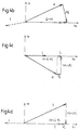
- Figs. 3a and 3b present voltage and current vectors clarifying the basic regulation of the systems, the filter coils being assumed to be ideal.
- Figs. 4a and 4b present the current and voltage vectors obtained when the resistances of the filter coils are taken into account.
- the mains rectifier shown in Fig. 1 is connected to a three-phase mains network L1 - L3 and comprises a pulse-width modulated (PWM) rectifier bridge 1 consisting of self-commutated power components, such as transistors T1 - T6, and diodes D1 - D6 connected in inverse-parallel with them, and the filtering components L and Cs of the mains and d.c. sides.
- PWM pulse-width modulated
- the measured voltages Er, Es and Et of the phases L1 - L3 of the supplying network are attenuated in an amplifier unit 2 to a level suited for the regulation electronics.
- the attenuated voltage signals are passed to a unit 11 where the real and imaginary components Ea and Eb of the spatial vector are calculated in a stationary coordinate system.
- the calculation is effected using generally known conversion formulas, which are also shown in the block representing unit 11 (e.g. Bühler:chip Quant geregelter Drehstromantriebe, Band 1, S. 49-50), and summing operational amplifier circuits.
- the imaginary component Eb is passed to a zero-point indicator 3 which outputs an inverted square wave synchronized with the voltage in question.
- This wave is applied to one input of the phase comparator 19 of a phase-locked loop PLL1 consisting of a phase comparator 19, PI-controller 20, voltage-controlled oscillator (VCO) 4 and a counter 5.
- the output of the phase comparator is applied to the input of the PI-controller 20, whose output determines the output frequency of the voltage-controlled oscillator (VCO) 4.
- the output of the oscillator (VCO) 4 is passed further to the counter 5, whose output is used as the address of a ROM unit 6.
- the ROM unit contains either one or two ROM circuits holding the pure sine or cosine curves. In the first alternative, the sine and cosine values are read in succession, and in the latter alternative, in parallel.
- the most-significant bit (msb) of the counter is applied to the other input of the phase comparator 19, and the sine and cosine curves are synchronized with the zero point of the imaginary component Eb of the localized voltage vector at which point the localized vector is on the real axis of the calculation coordinates.
- the sine and cosine values obtained from the ROM unit 6 are also the sine and cosine values of the phase angle of the spatial voltage vector in the stationary coordinate system.
- This equation is implemented using two multiplying D/A converters 12 and 13 and a summing operational amplifier 14.
- the procedure is simple and fast and it reduces the total response time, i.e. e.g. the time required for a change in the mains voltage to produce an effect on the control of the rectifier bridge 1.
- the real part Ea of the localized vector, obtained from block 11 is multiplied by the cosine, obtained from the ROM unit 6, of the new coordinate angle, and, similarly, in circuit 13 the imaginary part Eb is multiplied by the sine of the coordinate angle.
- the summer 14 performs the addition required by the conversion equation.
- the effective power taken by the mains rectifier can be directly influenced by the imaginary part or q-component of the localized vector of the rectifier voltages Ur, Us and Ut when a coordinate system tied to the mains voltage vector is used for reference.
- the reactive power is influenced by the real part or d-component of the localized vector.
- a system containing only an ideal mains filter coil L has a power factor of one.
- the d.c. voltage to be regulated is measured by an attenuating differential amplifier 7, and the measured voltage Udca thus obtained is compared in a difference circuit 9 to a voltage Udcr obtained from a reference unit 8.
- the difference quantity is fed into a controller 10 with a limited output providing the q-component Uq of the localized vector of the rectifier voltages.
- This component together with the d-component Ud , which is equal to the d-component Ed of the mains voltages, unambiguously determines the direction and magnitude of the localized vector describing the rectifier voltages.
- the real and imaginary localized vector components thus obtained are further converted in block 18 into three-phase modulation references Umr, Ums and Umt.
- the conversion is effected using summing operational amplifier circuits implementing the commonly known conversion equations presented in block 18.
- the modulation references Umr, Ums and Umt are compared by a comparator unit 22 to a triangular wave obtained from a carrier generator 21, the triangular wave being synchronized with the voltage-controlled oscillator (VCO) 4 in the phase-locked loop. This ensures that the modulation pulse references obtained from the comparator unit 22 contain no subharmonic components.
- the modulation pulse references obtained from the comparator unit 22 are passed via a base current amplifier unit 23 to the power components of the mains rectifier, which produce the desired rectifier voltages Ur, Us and Ut.
- Fig. illustrates another embodiment of the control system of the invention. It differs from the system in Fig. 1 as follows:
- Figures 3a and 3b show the current and voltage vectors I and U , which are used to clarify the principle of regulation of the effective and reactive powers of the system.
- Figures 4a - 4d show the current and voltage vectors in different cases when the resistances of the filtering coils L are taken into account.
- the magnitude of the d-component Ud must be changed by an amount equal to the vector R I , as shown by Figs. 4c and 4d.
- Fig. 4c represents a situation where power is flowing from the mains to the load, and Fig.
Landscapes
- Engineering & Computer Science (AREA)
- Power Engineering (AREA)
- Rectifiers (AREA)
- Control Of Motors That Do Not Use Commutators (AREA)
- Control Of Eletrric Generators (AREA)
Claims (10)
- Procédé pour la régulation de la tension continue d'un pont redresseur à modulation de largeur d'impulsion commandé par des composants semiconducteurs auto-commutés (T1-T6) et comportant des enroulements de filtrage (L), dans lequel les tensions de phase (Er,Es, Et) du réseau triphasé d'alimentation (L1,L2,L3) et la tension continue (Udc) du redresseur sont mesurées, dans lequel les références de modulation (Umr,Ums,Umt) utilisées dans la modulation de largeur d'impulsion sont synchronisées avec les tensions de réseau, avec des vecteurs localisés formés à partir de ces tensions ou avec des composantes de ces vecteurs, et dans lequel la régulation est effectuée dans un système de coordonnées lié au vecteur spatial (E) des tensions de réseau, les références de modulation (Umr,Ums,Umt) pour la modulation de largeur d'impulsion étant produites par utilisation de courbes de sinus et cosinus purs synchronisées avec les tensions de réseau, avec les vecteurs localisés formés à partir de ces tensions ou avec des composantes de ces vecteurs,au moyen d'une ou plusieurs boucles à blocage de phase (PLL1,PLL2),
caractérisé en ce que lesdites courbes de sinus et cosinus sont synchronisées par comparaison de l'angle de phase entre ledit vecteur localisé (E) des tensions de réseau et les coordonnées calculées au point zéro de la composante imaginaire (Eb) dudit vecteur localisé (E) de la tension de réseau, ou continuellement par ajustement de la composante imaginaire du vecteur de tension localisé à zéro dans le système de coordonnées utilisé. - Procédé suivant la revendication 1, caractérisé en ce que la composante imaginaire (Eb) du vecteur localisé est calculée à partir des tensions de phase (Er,Es,Et) dans un système de coordonnées fixe, en ce que ladite composante imaginaire est utilisée pour produire une onde rectangulaire synchronisée avec son point zéro et utilisée pour la commande de la boucle à blocage de phase (PLL1), et en ce que ladite boucle à blocage de phase (PLL1) produit les adresses d'un ou plusieurs circuits de mémoire dans lesquels sont stockées lesdites courbes de sinus et de cosinus.
- Procédé suivant la revendication 1, caractérisé en ce que la composante imaginaire (Eq) dudit vecteur localisé (E) de la tension de réseau est ajustée à zéro par calcul de la valeur effective (Eqa) de ladite composante (Eq), multiplication des composantes réelle et imaginaire (Ea,Eb) d'un système de coordonnées fixe correspondant à la tension de réseau (Er,Es,Et) par les valeurs de cosinus et de sinus de l'angle de coordonnées fournies par une boucle à blocage de phase (PLL2) conformément à des équations de conversion connues en elles-mêmes, comparaison de ladite valeur effective (Eqa) à une reférence de zéro (Eqr), introduction de la quantité différentielle ainsi obtenue dans une unité de commande (20) dont la sortie commande un oscillateur commandé par tension (4), et comptage des impulsions dudit oscillateur au moyen d'un compteur (5) dont la sortie estutilisée comme adresse d'une unité de mémoire (6) contenant les courbes de sinus et cosinus purs, et en ce que les valeurs de sinus et cosinus correspondant à l'adresse de ladite unité de mémoire sont utilisés pour le calcul de la valeur effective (Eqa) de ladite composante imaginaire.
- Procédé suivant la revendication 1, caractérisé en ce que la partie réelle (Ed) du vecteur de tension localisé correspondant à la valeur absolue des indicateurs de tension de phase, ladite partie réelle (Ed) étant la même que la composante réelle (Udr) du vecteur localisé (U) des tensions de redresseur, est calculée dans un système de coordonnées lié audit vecteur à partir des composantes réelle et imaginaire (Ea,Eb) du vecteur de tension localisé, d'une manière connue en elle-même, en ce que la tension continue (Udca) du redresseur est comparée à une référence (Udcr) et la quantité différentielle ainsi obtenue est introduite dans une unité de commande (10) qui fournit la composante imaginaire (Uqr) du vecteur localisé (U) des tensions de redresseur, en ce que lesdites composantes (Udr,Uqr) déterminent la direction et la grandeur du vecteur localisé décrivant les tensions de redresseur, et en ce que le vecteur localisé (U) correspondant aux tensions de.redresseur désirées (Ur,Us,Ut) est converti à un système de coordonnées fixe et les composantes réelle et imaginaire (Ua,Ub) du vecteur localisé ainsi obtenues sont ensuite converties en signaux de référence de modulation triphasés (Umr,Ums,Umt).
- Procédé suivant une quelconque des revendications précédentes, caractérisé en ce que la formation de la composante réelle (Udr) du dit vecteur localisé des tensions de redresseur (Ur,Us,Ut) est effectuée par déplacement vers l'avant ( 27) en fonction de la quantité différentielle entre la valeur mesurée de la tension continue (Udca) du pont redresseur et sa référence (Udcr).
- Procédé suivant une quelconque des revendications précédentes, caractérisé en ce que l'effet des résistances internes (R) des enroulements de filtrage (L) connectés aux tensions de réseau (Er,Es,Et) est éliminé au moyen d'une référence additionnelle proportionnelle à la composante imaginaire (Uqr).
- Procédé suivant une quelconque des revendications précédentes, caractérisé en ce que la valeur maximale permise de la composante réelle (Udr) dudit vecteur localisé des tensions de redresseur (Ur,Us,Ut) est diminuée lorsque la valeur absolue de la composante imaginaire (Uqr) augmente.
- Procédé suivant la revendication 3, caractérisé en ce que la multiplication des composantes réelle et imaginaire (Ea,Eb) dudit système de coordonnées fixe par les valeurs de cosinus et de sinus de l'angle obtenu à partir d'une boucle à blocage de phase (PLL2) est effectuée au moyen d'un ou plusieurs convertisseurs N/A (12′ ,13′).
- Procédé suivant la revendication 4, caractérisé en ce que le calcul de la partie réelle (Ed) dudit vecteur de tension localisé, cette partie réelle (Ed) étant la même que la composante réelle (Udr) du vecteur localisé (U) des tensions de redresseur, est effectué au moyen d'un ou plusieurs convertisseurs N/A de multiplication (12,13,12′,13′).
- Procédé suivant la revendication 4, caractérisé en ce que la conversion desdites tensions de redresseur désirées (Ur,Us,Ut) à un système de coordonnées fixe est effectuée au moyen d'un ou plusieurs convertisseurs N/A (15,16).
Applications Claiming Priority (2)
| Application Number | Priority Date | Filing Date | Title |
|---|---|---|---|
| FI902226A FI90294C (fi) | 1990-05-03 | 1990-05-03 | Menetelmä tasasuuntaajan tasajännitteen säätämiseksi |
| FI902226 | 1990-05-03 |
Publications (3)
| Publication Number | Publication Date |
|---|---|
| EP0455181A2 EP0455181A2 (fr) | 1991-11-06 |
| EP0455181A3 EP0455181A3 (en) | 1992-04-15 |
| EP0455181B1 true EP0455181B1 (fr) | 1995-07-05 |
Family
ID=8530370
Family Applications (1)
| Application Number | Title | Priority Date | Filing Date |
|---|---|---|---|
| EP91106880A Expired - Lifetime EP0455181B1 (fr) | 1990-05-03 | 1991-04-27 | Procédé pour la régulation de la tension continue d'un redresseur |
Country Status (8)
| Country | Link |
|---|---|
| US (1) | US5140514A (fr) |
| EP (1) | EP0455181B1 (fr) |
| AT (1) | ATE124827T1 (fr) |
| AU (1) | AU646038B2 (fr) |
| CA (1) | CA2041753C (fr) |
| DE (1) | DE69110966T2 (fr) |
| ES (1) | ES2074190T3 (fr) |
| FI (1) | FI90294C (fr) |
Cited By (1)
| Publication number | Priority date | Publication date | Assignee | Title |
|---|---|---|---|---|
| US8014181B2 (en) | 2009-09-29 | 2011-09-06 | General Electric Company | Power conversion control system |
Families Citing this family (22)
| Publication number | Priority date | Publication date | Assignee | Title |
|---|---|---|---|---|
| US5309078A (en) * | 1991-07-11 | 1994-05-03 | Sgs-Thomson Microelectronics, Inc. | Synchronous rectification method for reducing power dissipation in motor drivers in PWM mode |
| WO1995001670A1 (fr) * | 1993-06-29 | 1995-01-12 | Square D Company | Systeme de conversion de puissance ac-cc |
| US5428283A (en) * | 1994-05-26 | 1995-06-27 | Alliedsignal Inc. | Power factor control of pulse width modulated inverter supplied permanent magnet motor |
| JP2889133B2 (ja) * | 1994-11-02 | 1999-05-10 | 関西電力株式会社 | 電力変換器の制御装置 |
| JP3221828B2 (ja) * | 1996-02-16 | 2001-10-22 | 株式会社日立製作所 | 電力変換方法及び電力変換装置 |
| US7269034B2 (en) | 1997-01-24 | 2007-09-11 | Synqor, Inc. | High efficiency power converter |
| US5999417A (en) | 1997-01-24 | 1999-12-07 | Fische, Llc | High efficiency power converter |
| US6038152A (en) * | 1998-12-03 | 2000-03-14 | Baker; Donal E. | Active rectifier utilizing a fixed switching pattern |
| AT411414B (de) * | 2000-09-11 | 2003-12-29 | Kolar Johann W Dr Techn | Vorrichtung zur erzeugung der sollwerte der eingangsströme und der netzspannungsvorsteuersignale der eingangsstromregelung eines dreiphasen-dreipunkt- pulsgleichrichtersystems bei unsymmetrie des speisenden netzes |
| US6850426B2 (en) | 2002-04-30 | 2005-02-01 | Honeywell International Inc. | Synchronous and bi-directional variable frequency power conversion systems |
| US7308614B2 (en) | 2002-04-30 | 2007-12-11 | Honeywell International Inc. | Control sequencing and prognostics health monitoring for digital power conversion and load management |
| CN100433494C (zh) * | 2003-11-26 | 2008-11-12 | 力博特公司 | 不间断电源中整流器的矢量控制方法 |
| US7129677B2 (en) * | 2004-03-16 | 2006-10-31 | Tyco Electronics Power Systems, Inc. | Vector controller, a polyphase synchronous rectifier, and a method of vector-controlling thereof |
| US7190143B2 (en) * | 2005-05-27 | 2007-03-13 | Rockwell Automation Technologies, Inc. | Pulse width modulation (PWM) rectifier with variable switching frequency |
| DE102006015031A1 (de) | 2006-03-31 | 2007-10-11 | Siemens Ag | Verfahren zur Verringerung des Blindleistungsbedarfs eines grundfrequent getakteten netzseitigen Stromrichters im Leerlauf sowie bei geringer motorischer Belastung |
| US7542315B2 (en) * | 2006-11-30 | 2009-06-02 | Celis Semiconductor Corporation | Active rectifier |
| JP5259077B2 (ja) * | 2006-12-04 | 2013-08-07 | 株式会社京三製作所 | 瞬時電圧低下補償回路、電力変換装置、瞬時電圧低下補償方法及び瞬時電圧低下補償プログラム |
| FI119493B (fi) * | 2006-12-21 | 2008-11-28 | Vacon Oyj | Taajuusmuuttajan virran mittausjärjestely |
| IT1393871B1 (it) * | 2009-04-22 | 2012-05-11 | Ansaldo Energia Spa | Metodo di controllo vettoriale per motori elettrici |
| US10199950B1 (en) | 2013-07-02 | 2019-02-05 | Vlt, Inc. | Power distribution architecture with series-connected bus converter |
| CN109617550B (zh) * | 2018-11-27 | 2023-07-07 | 深圳市鼎泰佳创科技有限公司 | 基于二阶广义积分器的单相锁相环的控制方法 |
| CN110492472A (zh) * | 2019-07-16 | 2019-11-22 | 国网上海市电力公司 | 一种用于大型舰船的脉冲宽度调制岸电系统功率控制方法 |
Family Cites Families (7)
| Publication number | Priority date | Publication date | Assignee | Title |
|---|---|---|---|---|
| CH531272A (de) * | 1970-08-18 | 1972-11-30 | Siemens Ag | Einrichtung zur Steuerung netzgeführter Stromrichter, insbesondere für Anlagen zur Hochspannungs-Gleichstromübertragung |
| JPS60113663A (ja) * | 1983-11-25 | 1985-06-20 | Toshiba Corp | 位相検出装置 |
| DE3346291A1 (de) * | 1983-12-21 | 1985-07-04 | Siemens Ag | Verfahren und vorrichtung zum schnellen ermitteln einer netzsynchronen referenzspannung fuer einen netzgefuehrten stromrichter nach einer netzstoerung |
| DE3738181A1 (de) * | 1987-11-10 | 1989-05-18 | Siemens Ag | Vorrichtung zur regelung der gleichspannung eines netzgefuehrten stromrichters |
| JP2624793B2 (ja) * | 1988-08-12 | 1997-06-25 | 株式会社東芝 | Pwm昇圧コンバータの制御装置 |
| JPH02299471A (ja) * | 1989-05-12 | 1990-12-11 | Mitsubishi Electric Corp | Pwmコンバータ装置の制御方法 |
| JPH0710174B2 (ja) * | 1989-05-29 | 1995-02-01 | 三菱電機株式会社 | Pwmコンバータ装置 |
-
1990
- 1990-05-03 FI FI902226A patent/FI90294C/fi not_active IP Right Cessation
-
1991
- 1991-04-27 EP EP91106880A patent/EP0455181B1/fr not_active Expired - Lifetime
- 1991-04-27 AT AT91106880T patent/ATE124827T1/de not_active IP Right Cessation
- 1991-04-27 ES ES91106880T patent/ES2074190T3/es not_active Expired - Lifetime
- 1991-04-27 DE DE69110966T patent/DE69110966T2/de not_active Expired - Fee Related
- 1991-05-01 AU AU76322/91A patent/AU646038B2/en not_active Ceased
- 1991-05-02 CA CA002041753A patent/CA2041753C/fr not_active Expired - Fee Related
- 1991-05-03 US US07/695,057 patent/US5140514A/en not_active Expired - Lifetime
Cited By (1)
| Publication number | Priority date | Publication date | Assignee | Title |
|---|---|---|---|---|
| US8014181B2 (en) | 2009-09-29 | 2011-09-06 | General Electric Company | Power conversion control system |
Also Published As
| Publication number | Publication date |
|---|---|
| DE69110966T2 (de) | 1995-11-16 |
| FI90294B (fi) | 1993-09-30 |
| US5140514A (en) | 1992-08-18 |
| AU646038B2 (en) | 1994-02-03 |
| ES2074190T3 (es) | 1995-09-01 |
| AU7632291A (en) | 1991-11-07 |
| FI90294C (fi) | 1994-01-10 |
| EP0455181A2 (fr) | 1991-11-06 |
| DE69110966D1 (de) | 1995-08-10 |
| ATE124827T1 (de) | 1995-07-15 |
| CA2041753C (fr) | 1996-03-26 |
| CA2041753A1 (fr) | 1991-11-04 |
| FI902226A7 (fi) | 1991-11-04 |
| EP0455181A3 (en) | 1992-04-15 |
| FI902226A0 (fi) | 1990-05-03 |
Similar Documents
| Publication | Publication Date | Title |
|---|---|---|
| CA2041753C (fr) | Dispositif de regulation de la tension continue d'un redresseur | |
| US4729082A (en) | Control device for power converter | |
| US6771522B2 (en) | Inverter parallel operation system | |
| US6075350A (en) | Power line conditioner using cascade multilevel inverters for voltage regulation, reactive power correction, and harmonic filtering | |
| US5001619A (en) | Harmonics suppression control circuit for a PWM inverter | |
| US6166929A (en) | CSI based drive having active damping control | |
| US4459534A (en) | Method for controlling induction motor and apparatus therefor | |
| US5450029A (en) | Circuit for estimating a peak or RMS value of a sinusoidal voltage waveform | |
| US20090244937A1 (en) | Dc bus voltage harmonics reduction | |
| US6194864B1 (en) | Control device for induction motor | |
| US5594630A (en) | Add-on distortion scrubber for AC power systems | |
| US5065304A (en) | Controller for AC power converter | |
| Le Roux et al. | Integrated active rectifier and power quality compensator with reduced current measurement | |
| JPS58141699A (ja) | 電動機制御装置 | |
| US4764859A (en) | Method and apparatus for controlling circulating-current type cycloconverter | |
| JPS6038960B2 (ja) | インバ−タの電圧制御装置 | |
| JPH0432621B2 (fr) | ||
| EP0237012B1 (fr) | Appareil de commande pour convertisseurs de puissance à modulation de largeur d'impulsion | |
| JPH0698469A (ja) | 電圧検出形無効電力補償装置の制御方式 | |
| JPS63274374A (ja) | 電力変換器の制御回路 | |
| JPH01283085A (ja) | 変換装置の負荷角調節装置 | |
| JPH03212162A (ja) | パルス幅変調制御整流器の制御回路 | |
| JP2609229B2 (ja) | 循環電流形サイクロコンバータにおける制御装置 | |
| JP2607337Y2 (ja) | 電力変換回路の出力リミッタ回路 | |
| JP3230987B2 (ja) | 電力変換器の制御装置 |
Legal Events
| Date | Code | Title | Description |
|---|---|---|---|
| PUAI | Public reference made under article 153(3) epc to a published international application that has entered the european phase |
Free format text: ORIGINAL CODE: 0009012 |
|
| AK | Designated contracting states |
Kind code of ref document: A2 Designated state(s): AT BE DE ES FR GB IT NL SE |
|
| PUAL | Search report despatched |
Free format text: ORIGINAL CODE: 0009013 |
|
| AK | Designated contracting states |
Kind code of ref document: A3 Designated state(s): AT BE DE ES FR GB IT NL SE |
|
| 17P | Request for examination filed |
Effective date: 19921009 |
|
| 17Q | First examination report despatched |
Effective date: 19940428 |
|
| GRAA | (expected) grant |
Free format text: ORIGINAL CODE: 0009210 |
|
| AK | Designated contracting states |
Kind code of ref document: B1 Designated state(s): AT BE DE ES FR GB IT NL SE |
|
| REF | Corresponds to: |
Ref document number: 124827 Country of ref document: AT Date of ref document: 19950715 Kind code of ref document: T |
|
| REF | Corresponds to: |
Ref document number: 69110966 Country of ref document: DE Date of ref document: 19950810 |
|
| REG | Reference to a national code |
Ref country code: ES Ref legal event code: FG2A Ref document number: 2074190 Country of ref document: ES Kind code of ref document: T3 |
|
| ITF | It: translation for a ep patent filed | ||
| ET | Fr: translation filed | ||
| PLBE | No opposition filed within time limit |
Free format text: ORIGINAL CODE: 0009261 |
|
| STAA | Information on the status of an ep patent application or granted ep patent |
Free format text: STATUS: NO OPPOSITION FILED WITHIN TIME LIMIT |
|
| 26N | No opposition filed | ||
| REG | Reference to a national code |
Ref country code: GB Ref legal event code: IF02 |
|
| PGFP | Annual fee paid to national office [announced via postgrant information from national office to epo] |
Ref country code: AT Payment date: 20020307 Year of fee payment: 12 |
|
| PGFP | Annual fee paid to national office [announced via postgrant information from national office to epo] |
Ref country code: SE Payment date: 20030319 Year of fee payment: 13 |
|
| PGFP | Annual fee paid to national office [announced via postgrant information from national office to epo] |
Ref country code: BE Payment date: 20030402 Year of fee payment: 13 |
|
| REG | Reference to a national code |
Ref country code: GB Ref legal event code: 732E |
|
| PG25 | Lapsed in a contracting state [announced via postgrant information from national office to epo] |
Ref country code: AT Free format text: LAPSE BECAUSE OF NON-PAYMENT OF DUE FEES Effective date: 20030427 |
|
| REG | Reference to a national code |
Ref country code: FR Ref legal event code: CA Ref country code: FR Ref legal event code: TP |
|
| PG25 | Lapsed in a contracting state [announced via postgrant information from national office to epo] |
Ref country code: SE Free format text: LAPSE BECAUSE OF NON-PAYMENT OF DUE FEES Effective date: 20040428 |
|
| PG25 | Lapsed in a contracting state [announced via postgrant information from national office to epo] |
Ref country code: BE Free format text: LAPSE BECAUSE OF NON-PAYMENT OF DUE FEES Effective date: 20040430 |
|
| BERE | Be: lapsed |
Owner name: *KONE ELEVATOR G.M.B.H. Effective date: 20040430 |
|
| EUG | Se: european patent has lapsed | ||
| PGFP | Annual fee paid to national office [announced via postgrant information from national office to epo] |
Ref country code: FR Payment date: 20060313 Year of fee payment: 16 |
|
| PGFP | Annual fee paid to national office [announced via postgrant information from national office to epo] |
Ref country code: NL Payment date: 20060315 Year of fee payment: 16 |
|
| PGFP | Annual fee paid to national office [announced via postgrant information from national office to epo] |
Ref country code: ES Payment date: 20060405 Year of fee payment: 16 |
|
| NLV4 | Nl: lapsed or anulled due to non-payment of the annual fee |
Effective date: 20071101 |
|
| PG25 | Lapsed in a contracting state [announced via postgrant information from national office to epo] |
Ref country code: NL Free format text: LAPSE BECAUSE OF NON-PAYMENT OF DUE FEES Effective date: 20071101 |
|
| PGFP | Annual fee paid to national office [announced via postgrant information from national office to epo] |
Ref country code: GB Payment date: 20080320 Year of fee payment: 18 |
|
| REG | Reference to a national code |
Ref country code: ES Ref legal event code: FD2A Effective date: 20070428 |
|
| PG25 | Lapsed in a contracting state [announced via postgrant information from national office to epo] |
Ref country code: FR Free format text: LAPSE BECAUSE OF NON-PAYMENT OF DUE FEES Effective date: 20070430 |
|
| PGFP | Annual fee paid to national office [announced via postgrant information from national office to epo] |
Ref country code: DE Payment date: 20080320 Year of fee payment: 18 |
|
| PGFP | Annual fee paid to national office [announced via postgrant information from national office to epo] |
Ref country code: IT Payment date: 20080329 Year of fee payment: 18 |
|
| PG25 | Lapsed in a contracting state [announced via postgrant information from national office to epo] |
Ref country code: ES Free format text: LAPSE BECAUSE OF NON-PAYMENT OF DUE FEES Effective date: 20070428 |
|
| GBPC | Gb: european patent ceased through non-payment of renewal fee |
Effective date: 20090427 |
|
| PG25 | Lapsed in a contracting state [announced via postgrant information from national office to epo] |
Ref country code: DE Free format text: LAPSE BECAUSE OF NON-PAYMENT OF DUE FEES Effective date: 20091103 |
|
| PG25 | Lapsed in a contracting state [announced via postgrant information from national office to epo] |
Ref country code: GB Free format text: LAPSE BECAUSE OF NON-PAYMENT OF DUE FEES Effective date: 20090427 |
|
| PG25 | Lapsed in a contracting state [announced via postgrant information from national office to epo] |
Ref country code: IT Free format text: LAPSE BECAUSE OF NON-PAYMENT OF DUE FEES Effective date: 20090427 |