EP0456007B1 - Dispositif pour installation et adaptation des moyens de signalisation et/ou des moyens d'illumination routières - Google Patents
Dispositif pour installation et adaptation des moyens de signalisation et/ou des moyens d'illumination routières Download PDFInfo
- Publication number
- EP0456007B1 EP0456007B1 EP91105944A EP91105944A EP0456007B1 EP 0456007 B1 EP0456007 B1 EP 0456007B1 EP 91105944 A EP91105944 A EP 91105944A EP 91105944 A EP91105944 A EP 91105944A EP 0456007 B1 EP0456007 B1 EP 0456007B1
- Authority
- EP
- European Patent Office
- Prior art keywords
- traffic
- telescope
- functional part
- base part
- members
- Prior art date
- Legal status (The legal status is an assumption and is not a legal conclusion. Google has not performed a legal analysis and makes no representation as to the accuracy of the status listed.)
- Expired - Lifetime
Links
- 238000005286 illumination Methods 0.000 title claims description 6
- 230000003287 optical effect Effects 0.000 claims abstract description 10
- 238000010276 construction Methods 0.000 claims abstract description 9
- 239000011324 bead Substances 0.000 claims description 8
- 238000007789 sealing Methods 0.000 claims description 2
- 239000012858 resilient material Substances 0.000 claims 1
- 230000000717 retained effect Effects 0.000 claims 1
- 238000009434 installation Methods 0.000 abstract description 7
- 230000004888 barrier function Effects 0.000 description 15
- 230000005855 radiation Effects 0.000 description 5
- 238000000034 method Methods 0.000 description 4
- 230000000694 effects Effects 0.000 description 2
- 230000005540 biological transmission Effects 0.000 description 1
- 230000015572 biosynthetic process Effects 0.000 description 1
- 238000004040 coloring Methods 0.000 description 1
- 238000001514 detection method Methods 0.000 description 1
- 239000013013 elastic material Substances 0.000 description 1
- 229910052736 halogen Inorganic materials 0.000 description 1
- 150000002367 halogens Chemical class 0.000 description 1
- 230000007774 longterm Effects 0.000 description 1
Images





Classifications
-
- F—MECHANICAL ENGINEERING; LIGHTING; HEATING; WEAPONS; BLASTING
- F21—LIGHTING
- F21V—FUNCTIONAL FEATURES OR DETAILS OF LIGHTING DEVICES OR SYSTEMS THEREOF; STRUCTURAL COMBINATIONS OF LIGHTING DEVICES WITH OTHER ARTICLES, NOT OTHERWISE PROVIDED FOR
- F21V21/00—Supporting, suspending, or attaching arrangements for lighting devices; Hand grips
- F21V21/14—Adjustable mountings
- F21V21/24—Lazy-tongs
-
- B—PERFORMING OPERATIONS; TRANSPORTING
- B60—VEHICLES IN GENERAL
- B60Q—ARRANGEMENT OF SIGNALLING OR LIGHTING DEVICES, THE MOUNTING OR SUPPORTING THEREOF OR CIRCUITS THEREFOR, FOR VEHICLES IN GENERAL
- B60Q7/00—Arrangement or adaptation of portable emergency signal devices on vehicles
-
- E—FIXED CONSTRUCTIONS
- E01—CONSTRUCTION OF ROADS, RAILWAYS, OR BRIDGES
- E01F—ADDITIONAL WORK, SUCH AS EQUIPPING ROADS OR THE CONSTRUCTION OF PLATFORMS, HELICOPTER LANDING STAGES, SIGNS, SNOW FENCES, OR THE LIKE
- E01F9/00—Arrangement of road signs or traffic signals; Arrangements for enforcing caution
- E01F9/60—Upright bodies, e.g. marker posts or bollards; Supports for road signs
- E01F9/623—Upright bodies, e.g. marker posts or bollards; Supports for road signs characterised by form or by structural features, e.g. for enabling displacement or deflection
- E01F9/646—Upright bodies, e.g. marker posts or bollards; Supports for road signs characterised by form or by structural features, e.g. for enabling displacement or deflection extensible, collapsible or pivotable
-
- F—MECHANICAL ENGINEERING; LIGHTING; HEATING; WEAPONS; BLASTING
- F16—ENGINEERING ELEMENTS AND UNITS; GENERAL MEASURES FOR PRODUCING AND MAINTAINING EFFECTIVE FUNCTIONING OF MACHINES OR INSTALLATIONS; THERMAL INSULATION IN GENERAL
- F16M—FRAMES, CASINGS OR BEDS OF ENGINES, MACHINES OR APPARATUS, NOT SPECIFIC TO ENGINES, MACHINES OR APPARATUS PROVIDED FOR ELSEWHERE; STANDS; SUPPORTS
- F16M11/00—Stands or trestles as supports for apparatus or articles placed thereon ; Stands for scientific apparatus such as gravitational force meters
- F16M11/02—Heads
- F16M11/04—Means for attachment of apparatus; Means allowing adjustment of the apparatus relatively to the stand
- F16M11/043—Allowing translations
- F16M11/046—Allowing translations adapted to upward-downward translation movement
-
- F—MECHANICAL ENGINEERING; LIGHTING; HEATING; WEAPONS; BLASTING
- F16—ENGINEERING ELEMENTS AND UNITS; GENERAL MEASURES FOR PRODUCING AND MAINTAINING EFFECTIVE FUNCTIONING OF MACHINES OR INSTALLATIONS; THERMAL INSULATION IN GENERAL
- F16M—FRAMES, CASINGS OR BEDS OF ENGINES, MACHINES OR APPARATUS, NOT SPECIFIC TO ENGINES, MACHINES OR APPARATUS PROVIDED FOR ELSEWHERE; STANDS; SUPPORTS
- F16M11/00—Stands or trestles as supports for apparatus or articles placed thereon ; Stands for scientific apparatus such as gravitational force meters
- F16M11/20—Undercarriages with or without wheels
- F16M11/24—Undercarriages with or without wheels changeable in height or length of legs, also for transport only, e.g. by means of tubes screwed into each other
- F16M11/26—Undercarriages with or without wheels changeable in height or length of legs, also for transport only, e.g. by means of tubes screwed into each other by telescoping, with or without folding
- F16M11/28—Undercarriages for supports with one single telescoping pillar
-
- F—MECHANICAL ENGINEERING; LIGHTING; HEATING; WEAPONS; BLASTING
- F16—ENGINEERING ELEMENTS AND UNITS; GENERAL MEASURES FOR PRODUCING AND MAINTAINING EFFECTIVE FUNCTIONING OF MACHINES OR INSTALLATIONS; THERMAL INSULATION IN GENERAL
- F16M—FRAMES, CASINGS OR BEDS OF ENGINES, MACHINES OR APPARATUS, NOT SPECIFIC TO ENGINES, MACHINES OR APPARATUS PROVIDED FOR ELSEWHERE; STANDS; SUPPORTS
- F16M11/00—Stands or trestles as supports for apparatus or articles placed thereon ; Stands for scientific apparatus such as gravitational force meters
- F16M11/20—Undercarriages with or without wheels
- F16M11/24—Undercarriages with or without wheels changeable in height or length of legs, also for transport only, e.g. by means of tubes screwed into each other
- F16M11/38—Undercarriages with or without wheels changeable in height or length of legs, also for transport only, e.g. by means of tubes screwed into each other by folding, e.g. pivoting or scissors tong mechanisms
-
- F—MECHANICAL ENGINEERING; LIGHTING; HEATING; WEAPONS; BLASTING
- F16—ENGINEERING ELEMENTS AND UNITS; GENERAL MEASURES FOR PRODUCING AND MAINTAINING EFFECTIVE FUNCTIONING OF MACHINES OR INSTALLATIONS; THERMAL INSULATION IN GENERAL
- F16M—FRAMES, CASINGS OR BEDS OF ENGINES, MACHINES OR APPARATUS, NOT SPECIFIC TO ENGINES, MACHINES OR APPARATUS PROVIDED FOR ELSEWHERE; STANDS; SUPPORTS
- F16M13/00—Other supports for positioning apparatus or articles; Means for steadying hand-held apparatus or articles
- F16M13/02—Other supports for positioning apparatus or articles; Means for steadying hand-held apparatus or articles for supporting on, or attaching to, an object, e.g. tree, gate, window-frame, cycle
-
- G—PHYSICS
- G09—EDUCATION; CRYPTOGRAPHY; DISPLAY; ADVERTISING; SEALS
- G09F—DISPLAYING; ADVERTISING; SIGNS; LABELS OR NAME-PLATES; SEALS
- G09F13/00—Illuminated signs; Luminous advertising
- G09F13/02—Signs, boards, or panels, illuminated by artificial light sources positioned in front of the insignia
-
- G—PHYSICS
- G09—EDUCATION; CRYPTOGRAPHY; DISPLAY; ADVERTISING; SEALS
- G09F—DISPLAYING; ADVERTISING; SIGNS; LABELS OR NAME-PLATES; SEALS
- G09F13/00—Illuminated signs; Luminous advertising
- G09F13/04—Signs, boards or panels, illuminated from behind the insignia
- G09F13/0418—Constructional details
- G09F13/0472—Traffic signs
-
- F—MECHANICAL ENGINEERING; LIGHTING; HEATING; WEAPONS; BLASTING
- F16—ENGINEERING ELEMENTS AND UNITS; GENERAL MEASURES FOR PRODUCING AND MAINTAINING EFFECTIVE FUNCTIONING OF MACHINES OR INSTALLATIONS; THERMAL INSULATION IN GENERAL
- F16M—FRAMES, CASINGS OR BEDS OF ENGINES, MACHINES OR APPARATUS, NOT SPECIFIC TO ENGINES, MACHINES OR APPARATUS PROVIDED FOR ELSEWHERE; STANDS; SUPPORTS
- F16M2200/00—Details of stands or supports
- F16M2200/02—Locking means
- F16M2200/025—Locking means for translational movement
- F16M2200/027—Locking means for translational movement by friction
-
- F—MECHANICAL ENGINEERING; LIGHTING; HEATING; WEAPONS; BLASTING
- F16—ENGINEERING ELEMENTS AND UNITS; GENERAL MEASURES FOR PRODUCING AND MAINTAINING EFFECTIVE FUNCTIONING OF MACHINES OR INSTALLATIONS; THERMAL INSULATION IN GENERAL
- F16M—FRAMES, CASINGS OR BEDS OF ENGINES, MACHINES OR APPARATUS, NOT SPECIFIC TO ENGINES, MACHINES OR APPARATUS PROVIDED FOR ELSEWHERE; STANDS; SUPPORTS
- F16M2200/00—Details of stands or supports
- F16M2200/06—Arms
- F16M2200/061—Scissors arms
Definitions
- the invention relates to a device for attaching and aligning traffic facilities, including traffic signs and warning lights, and / or lighting devices on traffic areas, for example for securing traffic at construction or hazard locations, the actual traffic device and / or lighting device as a functional part on one of the Base part to be attached or set up traffic area is worn.
- Traffic devices and lighting devices of this type are known in a wide variety of designs and with a wide variety of information contents, for example as traffic signs, signposts, signposts, traffic control boards, barrier gates, barrier boards, etc.
- traffic signs are usually permanently attached to traffic areas, for example streets. However, they are also required for temporary attachment to construction sites and special danger spots.Lighting and warning devices are known both for the permanently installed traffic facilities and for the temporary traffic facilities that facilitate the detection of the respective traffic facilities in the dark and better attract the attention of road users to direct the respective traffic facilities.
- Warning lights are known as a special group of such traffic and lighting devices, which are used in particular at danger points and construction sites both during the day and at night. Such warning lights are often for short-term and quick use, for example Accident sites etc. known.
- the functional part containing the optical devices and the base part containing the electrical supply devices and switching devices are connected to one another to form a fixed unit of a warning light which is carried in motor vehicles of the police, fire service, technical aid agency, etc. and directly in the event of accidents or special operations removed from the vehicle and used for protection.
- Flash or halogen light is mainly used to improve the warning effect. Because of the limited space in the motor vehicle, such warning lights have to be kept as small and compact as possible. In the event of use, these warning lights are placed on the traffic area, for example on the street, and aligned with the incoming traffic. The mounting height is very low due to the necessary compact design of such warning lights, which means the lack that the first vehicle can only see the light, whereas the next and all other drivers can no longer see the light directly, i.e. the warning effect no longer exists or is insecure.
- warning lights In another known embodiment of the warning lights mentioned above, it is known in particular for use on construction sites to design the functional part and the base part of the warning light as two separate units, the functional part being placed on a shut-off part, for example on a beacon or barrier, and the base part on Foot of the shut-off part is parked. It then only extends from the connecting cable Base part for the functional part of the warning light. Warning lights of this design are only suitable to a limited extent for carrying in police, fire service etc. vehicles and for use on a case-by-case basis in the event of accidents or special operations, because the mounting parts carrying such shut-off parts are too bulky for this.
- the object of the invention is therefore to provide a device for attaching and aligning traffic facilities, including traffic signs and warning lights and / or lighting devices on traffic areas, which on the one hand have a compact design to be carried in emergency vehicles of the police, fire service, etc. and on the other hand the Create the possibility of being able to set up such traffic facilities or lighting facilities quickly and easily without any significant need for personnel and at the same time to install the functional part with the relevant information and warning content continuously in an effective position, for example at a suitable viewing height for the driver of motor vehicles, especially if such vehicles are approaching in a vehicle queue .
- a warning lamp with an upper part for receiving the optics and a lower part for receiving the power supply is known, in which a scissor gear is arranged between the upper and lower part.
- This warning light is transported in the compressed state of the scissor gear, so that its dimensions are not significantly larger than the usual warning lights during transport.
- the upper part with the light source is pulled out with the help of the scissors gear, so that the light source can be positioned in an effective position above the road surface.
- a disadvantage of this known warning light is that the scissor gear does not have sufficient rigidity and, for example, due to wind, the light source can oscillate back and forth.
- the scissors-type transmission can only be locked in this known warning light in the retracted or extended position, or at intermediate, fixed predetermined locking points, so that the upper part can not be continuously adjusted with respect to the lower part.
- EP-A-0 135 756 a hazard warning lamp which has an upper part which is height-adjustable relative to a lower part, the height being adjusted by telescopes which are accommodated in the lower part in the pushed-together state.
- the telescopes are designed such that they are locked in the extended position Condition can be held by a pawl.
- the pawl snaps onto a shoulder of the lower telescope, with one shoulder of the upper telescope reaching under the shoulder of the lower telescope.
- a major disadvantage of this hazard warning light is that a continuous adjustment of the upper part relative to the lower part is also not possible, since due to this configuration the telescopes can only be locked in the retracted or extended position.
- the invention proposes that the movable and changeable connecting device is provided in the manner of a telescopic rod between the base part and the functional part of the traffic device or lighting device.
- friction elements in the form of rings made of rubber-elastic material are inserted in such a way that the telescopic members can be moved axially relative to one another, but are held sufficiently firmly in a mutually set position for the transfer of the load of the functional part, so that the functional part can be selected in Desired position is adjustable relative to the base part, the friction elements between the adjacent telescopic members of the telescopic rod can be rolled.
- the invention provides a particularly advantageous method of assembly for the traffic facilities, including traffic signs and lighting devices, which are permanently or long-term installed on traffic areas.
- the invention offers particular advantage for temporarily used traffic facilities and lighting devices, in particular for warning lights.
- the invention provides a temporary warning light that can be set up at danger spots, construction sites, accident sites, etc. and that can be carried in emergency vehicles without requiring particular space.
- the base part should be designed in the manner of a foot part to be set up on the respective traffic area and that for supplying the any electrical devices or switching devices required in or on the functional part contain necessary.
- Such a unit with the base part designed as a foot part is to be set up at the point of use, while the functional part is brought into a suitable position by means of the movable and changeable connecting device. This work is simple, quick and can be carried out by a single person.
- the functional part can contain optical devices in the form of a light-beaming headlight to be aligned with the incoming traffic, the radiation direction of which can be set or adjusted essentially parallel to the traffic area.
- the functional part is adjustable up to approximately the driver's height and the light beam emanating from it is directed substantially at a constant height along the traffic area, for example a street.
- Such a warning light can thus be reliably recognized along a roadway and through the windows of the vehicles for the drivers of a plurality of vehicles arriving in a queue in a row.
- the telescopic members of the telescopic rod are concentrically fitting pieces of tube, all of which have the same length, such that the telescopic rod can be pushed together to the length of a single telescopic member.
- the telescopic rod is so low when pushed together that the overall height of the previous warning lamp units is not exceeded.
- the other dimensions, such as the length and width of the warning light, are no larger than those of the previous warning light units when the telescopic rod is pushed together.
- the warning light according to the invention in this embodiment fits into the receiving boxes present in emergency vehicles.
- the device according to the invention also offers the possibility of carrying other traffic devices and lighting devices in emergency vehicles, since the shield-shaped traffic signs, beacons, barriers and boards take up little space due to their flat design in vehicles and instead of the previous bulky assembly frames, a plurality of pushed together Telescopic poles can be carried easily.
- Two or more telescopic poles can be used for the installation of barrier barriers and larger barrier panels, which has the advantage that differences in height can also be compensated for when installing on sloping sites, for example road embankments, and horizontal arrangement of barriers etc. can be easily achieved.
- Conventional telescopic rods cannot be used for the assembly of traffic and lighting devices because only through the inventive installation of the locking devices or friction elements between the telescopic members of the telescopic rod have the requirements for the complete merging of the telescopic rod to the size of a single telescopic member been created.
- a particularly simple and surprising possibility for the design of the friction elements has emerged in the context of the invention that the telescopic members of the telescopic rod have a rounded cross-sectional shape and the friction elements are rings with a circular cross-section.
- the ring-shaped friction elements can be more easily rolled off if the ring has regions of greater thickness and regions of smaller thickness on its ring circumference in an essentially uniform spacing distribution.
- the areas of greater thickness can be substantially spherical.
- the telescopic members of the telescopic rod can be pipe sections which have, at one end - preferably the lower - a protruding bead or edge with a groove adjoining the pipe section and at the other end a stepped section with a reduced outer section compared to the pipe section - Have and inner diameter, such that the protruding bead or edge can still slide into the next larger pipe section, but not in its stepped section.
- the two elastic pieces of tube inserted are inserted into the annular groove before the telescopic rod is installed.
- the smaller piece of pipe is then inserted into the next larger piece of pipe and can be pushed through until the elastic ring comes to a stop against the shoulder formed at the beginning of the stepped section.
- the elastic ring emerges from the ring groove and is pressed between the inner surface of the larger pipe piece and the outer surface of the smaller pipe piece during the movement process so that a force is necessary to axially move the pipe pieces against one another.
- This avoids any unwanted mobility between the pipe sections in the telescopic rod, with the result that the telescopic rod automatically stops at any extension height and does not wobble. There is thus an automatic locking of the pipe sections of the telescopic rod in any position.
- the inserted rubber-elastic rings ensure sufficient friction of the pipe pieces against each other in any position of the telescopic rod, not only in the axial but also in the radial direction, so that there is also sufficient protection against rotation against accidental rotary movements.
- the anti-twist protection can be reinforced by choosing a non-circular but at least rounded, for example elliptical, cross-sectional shape instead of a circular cross-section of the pipe sections. It is also conceivable that the individual telescopic members of the telescopic rod have axially extending profiles in the manner of a tongue and groove combination that run into one another.
- the pipe sections can be designed to be slightly expanded just below the end position by increasing the inside diameter.
- the rubber-elastic ring is relieved here. There is no more friction and the pipe pieces practically collapse. Then no more force has to be used. Conversely, when the telescopic rod is pulled apart, force only has to be applied in a more or less long area before the end position.
- the traffic device according to the invention is particularly advantageous for the user when the same optical effect as with a traffic cone is achieved by alternately coloring the telescopic members of the telescopic rod in white and red.
- the warning light fulfills a double function: light + traffic cone.
- movable feet can be provided on the base part to enlarge the footprint. For example, such feet can be pivoted or pulled out in the base region of the base part.
- a omnidirectional emitter instead of a directional emitter with a warning light.
- the warning lamp can therefore be equipped with interchangeable lamp upper parts. This is made possible by the fact that the functional part containing the light source and the optical devices is detachably and / or interchangeably attached to the movable and changeable connecting device.
- a traffic or lighting device in particular a warning light
- a traffic or lighting device for special applications in its compact state, i.e. to be used with the connecting device pushed together between the functional part and the base part.
- the connecting device pushed together between the functional part and the base part.
- a switch can be provided which can be actuated by turning the functional part relative to the base part and / or the connecting device to switch the lamp on and off.
- the warning light shown in Figure 1 for comparison is a conventional design. It has a functional part 1 with a light source not visible here, e.g. a light bulb or a flash tube, which is in the focus of a light-bundling optical device 2.
- the base part 3 which is a power supply device e.g. Contains batteries or accumulators and an electrical or electronic circuit.
- This known warning light according to FIG. 1 is placed on the road as a unit in use and warns only the driver of a first vehicle in oncoming dense traffic, while it is not visible to the drivers of vehicles immediately behind.
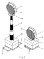
- a functional part 1 in the manner of a Headlight light-bundling optical device 2 and a base part 3 are provided.
- a connecting device is attached between the functional part 1 and the base part 3, by means of which the height of the functional part 1 can be adjusted in relation to the set-up base part.
- the direction of radiation of the headlamp can be set in the desired height position in a direction of radiation running essentially parallel to the traffic area.
- the lateral setting of the radiation direction along a street or the like is carried out by correspondingly setting up the warning lamp with its base part designed as a lamp base.
- the movable connecting device contains between the functional part 1 and the base part 3, a length-adjustable carrier for the functional part 1, which is designed in the manner of a telescopic rod 5.
- the base part 3 has extendable feet 6 which increase the stability of the warning light. Instead of the extendable feet 6, pivotable levers could also be provided as additional feet in the corner areas of the housing of the base part 3.
- parts 18 and 19 of a locking device are provided, which can be fixed by rotating the functional part 1 relative to the base part 3 such that the telescopic rod 5 cannot be pulled out.
- Figure 3 shows a section through the telescopic rod 5 in a preferred embodiment.
- the telescopic rod 5 is composed of tubular telescopic members 7, 8, 9, 10 of the same length, which have a round cross section can.
- the telescopic members 7, 8, 9, 10 have different diameters such that they can be arranged one inside the other. They are also shaped so that at one end - preferably the lower - a protruding bead 11 or edge with an annular groove 12 adjoining the tube and at the other end a stepped section 13 with a reduced outer and inner diameter compared to the tube is provided.
- the outer diameter of the protruding bead 11 is such that it can still slide in the tube section of the next largest telescopic member.
- a rubber-elastic ring 14 for example made of rubber or plastic, is provided, which is inserted into the annular groove 12 of each telescopic member 7, 8, 9, 10 before the assembly of the telescopic rod 5, after which the respective telescopic member with the next smallest diameter together with the ring 14 is inserted into the next largest telescopic member and pushed through until the ring comes to a stop on the shoulder formed by the section 13.
- the rubber-elastic rings 14 are moved out of their respective annular groove 12 and pressed and rolled between the inner surface of the larger and the outer surface of the respectively smaller tubular telescopic member of the telescopic rod 5 during the movement process. that a force is necessary to move the telescopic members 7, 8, 9, 10 against each other.
- the telescopic rod 5 remains at any extension height and does not tend to wobble its telescopic members 7, 8, 9, 10.
- the telescopic members 7 and 8 of the telescopic rod 5 shown there, for example, are in an intermediate position.
- the rubber-elastic ring 14 is pressed between the two telescopic members 7 and 8 and generates sufficient friction to hold the telescopic members 7 and 8 in a mutual position. Furthermore, the ring 14 forms a seal between the telescopic members 7 and 8.
- the telescopic members 7, 8, 9 and 10 are designed such that the lower bead 11 has changed directly into the tube shape without the formation of an annular groove above the bead 11.
- the ring is 14 even in the upper end position of the telescopic members under full pressure, so that the locking of the telescopic members 7, 8, 9, 10 in their end position should be even more secure.
- the introduction of the respective thinner tubes into the thicker tubes, that is, the assembly of the telescopic rod 5, is more difficult.
- the tubular telescopic members 7, 8, 9, 10 provided in the upper part of their main tubular section with a smaller outer diameter 15.
- the telescopic members 7, 8, 9, 10 can practically coincide when the rubber-elastic ring 14 reaches the area of smaller outside diameter.
- the telescopic rod 5 can be pulled out practically without force, as long as the rubber-elastic ring 14 is located in this area with a reduced outer diameter 15.
- the telescopic rod 5 is then no longer locked over its entire extension length in each extension position.
- FIG. 8 shows a modified embodiment of the rubber-elastic ring 14 used as the friction element.
- the ring 14 has a substantially uniform spacing on its circumference, spherically thickened regions 20 and regions 21 of reduced thickness in between. However, these areas of reduced thickness also have a circular cross section.
- the ring 14 is more easily movable between two adjacent telescopic members 7, 8, 9, 10 of the telescopic rod 5, even at lower temperatures.
- FIGS. 9 to 11 show details of the telescope, wherein axial profiles are provided in the manner of tongue and groove combinations, namely in the form of an axial groove or groove 16 and an axial rib or spring 17. These parts run with axial relative movement of the tubular telescopic members 7, 8, 9, 10 of the telescopic rod 5 into each other and prevent the telescopic members 7, 8, 9, 10 can be rotated against each other.
- a switch that can be actuated in a simplified manner for switching the warning light on and off can be provided, which can be actuated by rotating the functional part 1 relative to the connecting device and / or the base part 3.
- FIGS. 12 to 13 show another possible application of the connecting device between functional part 1 and base part 3 in its embodiment as a telescopic rod 5.
- the functional part 1 of the traffic device is a shut-off bar 22, which can be equipped with a number of optical devices 2 in the manner of warning lights on its upper side.
- the barrier bar 1 is attached to two telescopic rods 5. Each of these telescopic rods 5 sits on a base part 3.
- the power supply devices and switching devices required for the operation of the optical devices 2 can be accommodated in the base parts.
- the construction of the barrier with barrier bars 22 and telescopic rods 5 and base parts 3 offers the advantage that the telescopic rods 5 not only allow a desired height adjustment of the barrier beam 22, but also the compensation of differences in height of the sites caused by the terrain.
- the shut-off bar 22 can thereby be aligned horizontally at any time.
- the example in FIG. 13 is a Traffic board 23, which is set up permanently or temporarily on traffic areas by means of a conventional mounting frame 24.
- a lighting device 25 is arranged above and in front of the traffic board 23 on the mounting frame 24.
- This lighting device 25 is fastened to the mounting frame by means of a telescopic rod 5.
- the mounting frame 24 represents the common base part 3 for the traffic sign 23 and the lighting device 25.
- a further base part can also be provided which carries the telescopic rod 5 and the power supply devices and switching devices required for the lighting device 25 contains.
- the attachment of the lighting device 25 by means of a telescopic rod 5 arranged horizontally in this case offers the advantage that the distance of the lighting device 25 in front of the traffic sign 23 can be adjusted and thus the angle of incidence of the light beams hitting the traffic sign 23. This is of particular importance for traffic signs with a reflective surface.
- the optimal direction of radiation of the light reflected by the traffic sign 23 with respect to the road users moving towards the traffic sign can be set.
- a large number of other possible uses of the movable, changeable connecting device on traffic devices and lighting devices to be used in traffic are possible, in particular in their embodiment as a telescopic rod 5.
Landscapes
- Engineering & Computer Science (AREA)
- General Engineering & Computer Science (AREA)
- Mechanical Engineering (AREA)
- Physics & Mathematics (AREA)
- General Physics & Mathematics (AREA)
- Theoretical Computer Science (AREA)
- Architecture (AREA)
- Civil Engineering (AREA)
- Structural Engineering (AREA)
- Road Signs Or Road Markings (AREA)
- Traffic Control Systems (AREA)
- Non-Portable Lighting Devices Or Systems Thereof (AREA)
Claims (20)
- Dispositif pour installer et orienter des équipements pour la circulation, y compris des signaux routiers et des lampes de signalisation et d'avertissement, et/ou des systèmes d'éclairage dans des zones de circulation, par exemple pour la sécurité de la circulation à proximité des chantiers et des endroits dangereux, l'équipement pour la circulation et/ou le système d'éclairage proprement dit étant supporté en tant que partie fonctionnelle (1) sur un élément de base (3) à placer ou à installer dans la zone de circulation, et un dispositif de liaison mobile et modifiable étant prévu entre l'élément de base (3) et la partie fonctionnelle (1) de l'équipement pour la circulation ou du système d'éclairage,
caractérisé en ce que le dispositif de liaison mobile est réalisé sous la forme d'une tige télescopique (5), et entre les éléments télescopiques (7, 8, 9, 10) coulissant les uns dans les autres et constituant la tige télescopique (5), sont insérés des éléments de frottement sous la forme de bagues (14) à base de matériau en caoutchouc élastique de telle façon que les éléments télescopiques soient mobiles axialement les uns par rapport aux autres, mais soient maintenus suffisamment solidement dans la position réciproque réglée pour le support de la charge de la partie fonctionnelle (1), de sorte que la partie fonctionnelle (1) puisse être réglée au choix dans la position souhaitée par rapport à l'élément de base (3), les éléments de frottement pouvant être déroulés entre les éléments télescopiques respectivement voisins de la tige télescopique (5). - Dispositif selon la revendication 1, caractérisé en ce que les éléments de frottement sont réalisés en même temps comme des éléments d'étanchéité élastiques et agissant entre les éléments télescopiques (7, 8, 9, 10) respectivement voisins de la tige télescopique (5).
- Dispositif selon la revendication 1 ou 2, caractérisé en ce que les éléments télescopiques (7, 8, 9, 10) de la tige télescopique (5) sont des tronçons de tubes adaptés de façon concentrique qui présentent tous la même longueur, de telle sorte que la tige télescopique (5) puisse être télescopée sur la longueur d'un seul élément télescopique.
- Dispositif selon l'une quelconque des revendications 1 à 3, caractérisé en ce que les éléments télescopiques (7, 8, 9, 10) de la tige télescopique (5) présentent une forme de section arrondie et les éléments de frottement sont des bagues (14) de section circulaire.
- Dispositif selon la revendication 4, caractérisé en ce que la bague (14) présente à sa périphérie des zones (20) d'épaisseur plus importante et des zones (21) d'épaisseur plus faible réparties à des intervalles sensiblement réguliers.
- Dispositif selon la revendication 5, caractérisé en ce que les zones (20) d'épaisseur assez importante sont réalisées avec une forme pratiquement sphérique.
- Dispositif selon la revendication 4, caractérisé en ce que les éléments télescopiques (7, 8, 9, 10) de la tige télescopique (5) sont des tronçons de tubes qui présentent à une extrémité, de préférence l'extrémité inférieure, un renflement (11) saillant ou un bord avec une rainure (12) faisant suite en direction du tronçon de tube et à l'autre extrémité un tronçon (15) en déport avec un diamètre extérieur et un diamètre intérieur réduits par rapport au bout de tuyau, de telle sorte que le renflement (11) saillant ou le bord puisse glisser encore dans le bout de tuyau de l'élément télescopique immédiatement supérieur, mais pas dans son tronçon (15) en déport.
- Dispositif selon l'une quelconque des revendications 1 à 7, caractérisé en ce qu'un élément télescopique terminal, de préférence l'élément extrême (10), de la tige télescopique (5) est relié de façon fixe au corps de l'élément de base (3).
- Dispositif selon l'une quelconque des revendications 1 à 8, caractérisé en ce que le corps de l'élément de base (3) est réalisé pour recevoir la tige télescopique (5) repliée dans sa partie intérieure.
- Dispositif selon l'une quelconque des revendications 1 à 9, caractérisé en ce que les éléments télescopiques (7, 8, 9, 10) de la tige télescopique (5) sont protégés contre une torsion réciproque autour de leur axe longitudinal.
- Dispositif selon la revendication 10, caractérisé en ce que les éléments télescopiques (7, 8, 9, 10) de la tige télescopique (5) ont une forme de section non circulaire.
- Dispositif selon la revendication 10, caractérisé en ce que les différents éléments télescopiques (7, 8, 9, 10) de la tige télescopique (5) présentent des profilages (16, 17) s'étendant axialement sous la forme d'une combinaison de languettes et de rainures qui coulissent les unes dans les autres.
- Dispositif selon l'une quelconque des revendications 1 à 12, caractérisé en ce que les éléments télescopiques (7, 8, 9, 10) de la tige télescopique (5) sont colorés alternativement en rouge et en blanc.
- Dispositif selon l'une quelconque des revendications 1 à 13, pour des équipements de circulation et des systèmes d'éclairage pouvant être mis en place provisoirement, par exemple des lampes de signalisation, caractérisé en ce que l'élément de base (3) se présente sous la forme d'une partie avec pied à installer dans la zone de circulation respective et contient les dispositifs d'alimentation électrique et les dispositifs de commutation nécessaires pour l'alimentation des équipements électriques éventuellement installés dans ou sur la partie fonctionnelle (1).
- Dispositif selon la revendication 14, caractérisé en ce que la partie fonctionnelle (1) contient des dispositifs optiques (2) sous la forme d'un projecteur à orienter vers le trafic d'arrivée et focalisant la lumière, dont le sens d'éclairage est réglé ou peut être réglé sensiblement parallèlement à la zone de circulation.
- Dispositif selon la revendication 14, caractérisé en ce que sont prévus, sur l'élément de base (3), des pieds (6) mobiles vers l'extérieur pour agrandir la surface d'assise.
- Dispositif selon la revendication 16, caractérisé en ce que les pieds (6) sont disposés de façon à pouvoir pivoter vers l'extérieur ou à être étirés à partir de la zone de fond de l'élément de base (3).
- Dispositif selon l'une quelconque des revendications 1 à 17, caractérisé en ce que la partie fonctionnelle (1) est disposée de façon amovible et/ou interchangeable sur le dispositif de liaison mobile et modifiable.
- Dispositif selon l'une quelconque des revendications 1 à 18, caractérisé en ce que la partie fonctionnelle (1), l'élément de base (3) et/ou le dispositif de liaison sont équipés de systèmes de blocage (18, 19) empêchant l'extraction du dispositif de liaison, qui peuvent être réglés par la rotation de la partie fonctionnelle par rapport à l'élément de base dans et à partir de la position d'arrêt.
- Dispositif selon l'une quelconque des revendications 1 à 19, caractérisé en ce qu'est prévu un interrupteur qui peut être actionné par le mouvement de rotation de la partie fonctionnelle (1) par rapport à l'élément de base (3) et/ou du dispositif de liaison pour la connexion et la déconnexion des équipements électriques éventuellement contenus dans la partie fonctionnelle (1).
Applications Claiming Priority (2)
| Application Number | Priority Date | Filing Date | Title |
|---|---|---|---|
| DE4012459A DE4012459A1 (de) | 1990-04-19 | 1990-04-19 | Warnleuchte |
| DE4012459 | 1990-04-19 |
Publications (3)
| Publication Number | Publication Date |
|---|---|
| EP0456007A2 EP0456007A2 (fr) | 1991-11-13 |
| EP0456007A3 EP0456007A3 (en) | 1992-04-15 |
| EP0456007B1 true EP0456007B1 (fr) | 1996-02-07 |
Family
ID=6404649
Family Applications (1)
| Application Number | Title | Priority Date | Filing Date |
|---|---|---|---|
| EP91105944A Expired - Lifetime EP0456007B1 (fr) | 1990-04-19 | 1991-04-14 | Dispositif pour installation et adaptation des moyens de signalisation et/ou des moyens d'illumination routières |
Country Status (3)
| Country | Link |
|---|---|
| EP (1) | EP0456007B1 (fr) |
| AT (1) | ATE134011T1 (fr) |
| DE (2) | DE4012459A1 (fr) |
Families Citing this family (15)
| Publication number | Priority date | Publication date | Assignee | Title |
|---|---|---|---|---|
| IT233754Y1 (it) * | 1994-12-16 | 2000-02-03 | Bruno Biasci | Elemento di segnalazione luminoso di veicoloi fermo, collassabile con ulteriore segnale luminoso inmtermittente |
| US6769380B1 (en) * | 2002-07-05 | 2004-08-03 | Producciones Generales-Progen S.A. | Modular marker |
| ES2279662B2 (es) * | 2004-12-02 | 2008-05-16 | Juan Carlos Huercano De La Orden | Señalizacion provisional ensamblable. |
| HRP20171132T1 (hr) * | 2007-04-16 | 2017-12-15 | Falck Schmidt Defence Systems A/S | Teleskopski stup |
| DE102014204976A1 (de) * | 2014-01-10 | 2015-07-16 | Adolf Nissen Elektrobau Gmbh + Co. Kg | Verkehrsbake |
| CN106436606B (zh) * | 2016-08-31 | 2018-10-30 | 无锡优萌模塑制造有限公司 | 一种可折叠塑料路锥 |
| CN107326825B (zh) * | 2017-07-16 | 2019-10-25 | 东阳市新意工业产品设计有限公司 | 一种高速公路广告牌 |
| CN109204128A (zh) * | 2018-09-28 | 2019-01-15 | 安徽省中车科技有限公司 | 一种可调节高度的汽车三脚架 |
| CN109210332A (zh) * | 2018-10-19 | 2019-01-15 | 东营职业学院 | 一种机械教学用多功能拆装台 |
| CN109267511B (zh) * | 2018-10-23 | 2020-11-20 | 东阳市晨旭建筑工程设计有限公司 | 桥梁施工用安全警示装置 |
| CN109253361B (zh) * | 2018-11-19 | 2021-02-09 | 佛山科学技术学院 | 一种基于智能交通管理系统控制的交通信息显示装置 |
| CN110726103B (zh) * | 2019-10-21 | 2021-08-13 | 常州机电职业技术学院 | 便携式可升降折叠台灯 |
| CN111048011A (zh) * | 2020-02-21 | 2020-04-21 | 广州进观智能设备有限公司 | 一种基于人工智能的三角警示牌放置装置 |
| CN114542865A (zh) * | 2022-01-28 | 2022-05-27 | 浙江天璇智控科技有限公司 | 一种信标安装座及安装组件 |
| US11935434B1 (en) * | 2023-05-16 | 2024-03-19 | Tekky | Pop-up prop module and apparatus |
Family Cites Families (5)
| Publication number | Priority date | Publication date | Assignee | Title |
|---|---|---|---|---|
| DE1534581C3 (de) * | 1965-12-10 | 1974-10-17 | Erich 8011 Ingelsberg Weichenrieder | Leitpfosten für Straßen mit einem ausziehbaren Schneezeichen |
| US4083033A (en) * | 1976-05-07 | 1978-04-04 | Royal Industries, Inc. | Traffic control element |
| GB2067236A (en) * | 1980-01-10 | 1981-07-22 | Topley D M | Portable crossing sign |
| US4613847A (en) * | 1983-08-08 | 1986-09-23 | Life Light Systems | Emergency signal |
| DE8528823U1 (de) * | 1985-10-10 | 1987-02-12 | Horizont Gerätewerk GmbH, 3540 Korbach | Warnleuchte |
-
1990
- 1990-04-19 DE DE4012459A patent/DE4012459A1/de not_active Withdrawn
-
1991
- 1991-04-14 DE DE59107370T patent/DE59107370D1/de not_active Expired - Fee Related
- 1991-04-14 AT AT91105944T patent/ATE134011T1/de not_active IP Right Cessation
- 1991-04-14 EP EP91105944A patent/EP0456007B1/fr not_active Expired - Lifetime
Also Published As
| Publication number | Publication date |
|---|---|
| DE59107370D1 (de) | 1996-03-21 |
| DE4012459A1 (de) | 1991-10-24 |
| EP0456007A3 (en) | 1992-04-15 |
| EP0456007A2 (fr) | 1991-11-13 |
| ATE134011T1 (de) | 1996-02-15 |
Similar Documents
| Publication | Publication Date | Title |
|---|---|---|
| EP0456007B1 (fr) | Dispositif pour installation et adaptation des moyens de signalisation et/ou des moyens d'illumination routières | |
| EP1066188B1 (fr) | Dispositif rotatif | |
| DE3341621A1 (de) | Schild mit zugehoerigem staender | |
| EP2637896A1 (fr) | Mât | |
| DE2410627A1 (de) | Traeger fuer hinweisschilder, insbesondere verkehrsschilder | |
| DE102009042257A1 (de) | Handlauf mit integrierten Leuchtmitteln | |
| DE2746367C2 (fr) | ||
| AT5157U1 (de) | Antennengehäuse | |
| DE69110469T2 (de) | Leuchtanlage zur bezeichnung der sperrung einer fahrbahn, und zur umleitung des verkehrs. | |
| EP1623154A1 (fr) | Dispositif d'eclairage | |
| DE102005048908A1 (de) | Gleitwinkelfeuer zur Anflugführung von Flugzeugen | |
| DE10060799C2 (de) | Anordnung zur Erfassung von sich nähernden Fahrzeugen, insbesondere von in falscher Richtung fahrenden Fahrzeugen | |
| EP3869095B1 (fr) | Point lumineux modulaire | |
| DE69836850T2 (de) | Umstellbare, auf dem Boden stehende, Verkehrsleiteinrichtung für Fahrspuren | |
| DE102010053005A1 (de) | Warnleuchte und mit einer Warnleuchte ausgerüsteter Teleskopmast | |
| EP3770486B1 (fr) | Luminaire d'éclairage public destiné à la prévention de la mortalité animale due aux véhicules | |
| DE202011051740U1 (de) | Lampenhalter für eine Einbauleuchte | |
| DE4116786A1 (de) | Anlage zur schnellen absicherung von gefahrenstellen auf schnellverkehrsstrassen und zur gleichzeitigen notrufausloesung | |
| DE2232817C3 (de) | Notwarnleuchte | |
| CH707968A2 (de) | Fussgängerlichtsignalanlage. | |
| AT517086B1 (de) | Leitpflock | |
| DE871582C (de) | Blendungsfreie Beleuchtungsweise sowie Beleuchtungsanlage fuer einander entgegenkommende Kraftfahrzeuge | |
| AT13948U1 (de) | Vorrichtung zum Anheben und Absenken von Lasten | |
| DE9202043U1 (de) | Verkehrswarnanlage | |
| DE202023101908U1 (de) | Brandschutzvorrichtung sowie Beförderungsfahrzeug hierfür |
Legal Events
| Date | Code | Title | Description |
|---|---|---|---|
| PUAI | Public reference made under article 153(3) epc to a published international application that has entered the european phase |
Free format text: ORIGINAL CODE: 0009012 |
|
| AK | Designated contracting states |
Kind code of ref document: A2 Designated state(s): AT BE CH DE DK FR GB IT LI NL SE |
|
| PUAL | Search report despatched |
Free format text: ORIGINAL CODE: 0009013 |
|
| AK | Designated contracting states |
Kind code of ref document: A3 Designated state(s): AT BE CH DE DK FR GB IT LI NL SE |
|
| 17P | Request for examination filed |
Effective date: 19920511 |
|
| 17Q | First examination report despatched |
Effective date: 19930422 |
|
| RBV | Designated contracting states (corrected) |
Designated state(s): AT CH DE FR GB LI |
|
| GRAA | (expected) grant |
Free format text: ORIGINAL CODE: 0009210 |
|
| AK | Designated contracting states |
Kind code of ref document: B1 Designated state(s): AT CH DE FR GB LI |
|
| REF | Corresponds to: |
Ref document number: 134011 Country of ref document: AT Date of ref document: 19960215 Kind code of ref document: T |
|
| REF | Corresponds to: |
Ref document number: 59107370 Country of ref document: DE Date of ref document: 19960321 |
|
| GBT | Gb: translation of ep patent filed (gb section 77(6)(a)/1977) |
Effective date: 19960222 |
|
| REG | Reference to a national code |
Ref country code: CH Ref legal event code: NV Representative=s name: E. BLUM & CO. PATENTANWAELTE |
|
| PG25 | Lapsed in a contracting state [announced via postgrant information from national office to epo] |
Ref country code: AT Effective date: 19960414 |
|
| PG25 | Lapsed in a contracting state [announced via postgrant information from national office to epo] |
Ref country code: LI Effective date: 19960430 Ref country code: CH Effective date: 19960430 |
|
| ET | Fr: translation filed | ||
| REG | Reference to a national code |
Ref country code: CH Ref legal event code: PL |
|
| PLBE | No opposition filed within time limit |
Free format text: ORIGINAL CODE: 0009261 |
|
| STAA | Information on the status of an ep patent application or granted ep patent |
Free format text: STATUS: NO OPPOSITION FILED WITHIN TIME LIMIT |
|
| 26N | No opposition filed | ||
| PGFP | Annual fee paid to national office [announced via postgrant information from national office to epo] |
Ref country code: GB Payment date: 19970318 Year of fee payment: 7 |
|
| PGFP | Annual fee paid to national office [announced via postgrant information from national office to epo] |
Ref country code: FR Payment date: 19980216 Year of fee payment: 8 |
|
| PG25 | Lapsed in a contracting state [announced via postgrant information from national office to epo] |
Ref country code: GB Free format text: LAPSE BECAUSE OF NON-PAYMENT OF DUE FEES Effective date: 19980414 |
|
| GBPC | Gb: european patent ceased through non-payment of renewal fee |
Effective date: 19980414 |
|
| PG25 | Lapsed in a contracting state [announced via postgrant information from national office to epo] |
Ref country code: FR Free format text: LAPSE BECAUSE OF NON-PAYMENT OF DUE FEES Effective date: 19991231 |
|
| REG | Reference to a national code |
Ref country code: FR Ref legal event code: ST |
|
| PGFP | Annual fee paid to national office [announced via postgrant information from national office to epo] |
Ref country code: DE Payment date: 20010615 Year of fee payment: 11 |
|
| PG25 | Lapsed in a contracting state [announced via postgrant information from national office to epo] |
Ref country code: DE Free format text: LAPSE BECAUSE OF NON-PAYMENT OF DUE FEES Effective date: 20021101 |