EP0456523A2 - Niederdruck-Spritzpistole - Google Patents
Niederdruck-Spritzpistole Download PDFInfo
- Publication number
- EP0456523A2 EP0456523A2 EP91304286A EP91304286A EP0456523A2 EP 0456523 A2 EP0456523 A2 EP 0456523A2 EP 91304286 A EP91304286 A EP 91304286A EP 91304286 A EP91304286 A EP 91304286A EP 0456523 A2 EP0456523 A2 EP 0456523A2
- Authority
- EP
- European Patent Office
- Prior art keywords
- air
- paint
- bore
- nozzle
- spray gun
- Prior art date
- Legal status (The legal status is an assumption and is not a legal conclusion. Google has not performed a legal analysis and makes no representation as to the accuracy of the status listed.)
- Granted
Links
Images


Classifications
-
- B—PERFORMING OPERATIONS; TRANSPORTING
- B05—SPRAYING OR ATOMISING IN GENERAL; APPLYING FLUENT MATERIALS TO SURFACES, IN GENERAL
- B05B—SPRAYING APPARATUS; ATOMISING APPARATUS; NOZZLES
- B05B7/00—Spraying apparatus for discharge of liquids or other fluent materials from two or more sources, e.g. of liquid and air, of powder and gas
- B05B7/0081—Apparatus supplied with low pressure gas, e.g. "hvlp"-guns; air supplied by a fan
-
- B—PERFORMING OPERATIONS; TRANSPORTING
- B05—SPRAYING OR ATOMISING IN GENERAL; APPLYING FLUENT MATERIALS TO SURFACES, IN GENERAL
- B05B—SPRAYING APPARATUS; ATOMISING APPARATUS; NOZZLES
- B05B7/00—Spraying apparatus for discharge of liquids or other fluent materials from two or more sources, e.g. of liquid and air, of powder and gas
- B05B7/02—Spray pistols; Apparatus for discharge
- B05B7/08—Spray pistols; Apparatus for discharge with separate outlet orifices, e.g. to form parallel jets, i.e. the axis of the jets being parallel, to form intersecting jets, i.e. the axis of the jets converging but not necessarily intersecting at a point
- B05B7/0807—Spray pistols; Apparatus for discharge with separate outlet orifices, e.g. to form parallel jets, i.e. the axis of the jets being parallel, to form intersecting jets, i.e. the axis of the jets converging but not necessarily intersecting at a point to form intersecting jets
- B05B7/0815—Spray pistols; Apparatus for discharge with separate outlet orifices, e.g. to form parallel jets, i.e. the axis of the jets being parallel, to form intersecting jets, i.e. the axis of the jets converging but not necessarily intersecting at a point to form intersecting jets with at least one gas jet intersecting a jet constituted by a liquid or a mixture containing a liquid for controlling the shape of the latter
Definitions
- This invention relates to an air spray gun to be suitably used for atomizing and spraying paint by compressed air and more particularly it relates to an air spray gun capable of spraying paint under low air pressure to prevent generation and dissipation of misty paint and enhance the efficiency of painting.
- a known air spray gun for atomizing and spraying paint by compressed air typically comprises a round paint nozzle through which paint is ejected in a jet stream and a number of air nozzles annularly arranged around the paint nozzle through which compressed air is driven out in order to atomize the paint being ejected.
- the arrangement of the air nozzles may be modified to meet the specific requirements of painting at a given work site and maximize the effect of painting.
- the air pressure to be used for spraying paint by such an air spray gun is normally found between 2.5 and 5kgf/cm2 so that the paint may be ejected through the paint nozzle under the pressure of 0.5 to 3kgf/cm2 unless a highly viscous paint is involved.
- the Japanese Industrial Standard (JIS) provides that the bore of the paint nozzle should be between 0.5mm and 2.5mm ⁇ and most nozzles available in Japan have inner diameters found within this range.
- an airless spray gun designed to force out paint under high pressure so that the paint can be rendered to fine particles in the atmosphere without using compressed air.
- Such an airless spray gun normally comprises a spray nozzle having an oblong opening to produce a sector-like jet stream of paint. While it can considerably overcome the problem of dissipated paint, it requires a pressure as high as 100kgf/cm2 to be applied to the paint and a specially designed high pressure pump to produce such a high pressure. Since the paint should be ejected at a high rate, this technique cannot suitably used for low viscous paints and thin paint coatings. Moreover, such a spray gun cannot produce satisfactorily fine paint particles and the sector-shaped jet stream can accompany at the lateral edges tails which are detrimental to the effect of spraying.
- a paint atomizing apparatus that comprises a nozzle having an oblong opening and arranged within an air cap also having an oblong opening so that the paint ejected from said nozzle in the form of a flat jet stream is surrounded by an evenly flowing air stream and then forced out of the air cap under atomized condition.
- the air spray gun which is handy and can provide a fine and delicate finish is most conspicu- ously accompanied by the problem of paint dissipation and therefore most seriously requires improvements in terms of this problem.
- an air spray gun comprising a nozzle with a frusto-conically profiled tip, a cylindrical through bore, a pair of V-shaped grooves running along said through bore and an oblong opening for ejecting paint under a pressure of 1 to 6kgf/cm2 and atomizing said ejected paint by compressed air having a pressure of 0.5 to 2kgf/cm2, wherein an air cap is arranged to form an annular air outlet between the outer periphery of the nozzle tip and a central air outlet of the air cap and said nozzle tip is located within in a front central through bore of the air cap.
- An air spray gun preferably comprises at least a pair of auxiliary air outlets arranged in juxtaposition across the axis of the oblong opening to make the air jet streams from said air outlets to cross and crash the paint stream and at least a pair of angular air outlets to make the air jet streams from said angular air outlets to cross and crash the paint stream downstream the first crossing and perpendicular to the first air jet streams so that the paint may be atomized under relatively low air pressure to prevent paint dissipation and consequently enhance the efficiency of painting.
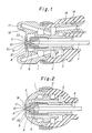
- Fig. 1 is a sectional view of a first preferred embodiment of the spray gun of the invention, showing only the atomizer thereof.
- Fig. 2 is another sectional view of the atomizer of Fig. 1 cut along a plane perpendicular to the plane of Fig. 1.
- Fig. 3 is a sectional view of the embodiment of Fig. 1, showing the entire spray gun.
- Fig. 4 is a front view of the air cap of the embodiment of Fig. 1.
- Fig. 5 is a sectional view of a second embodiment of the spray gun of the invention, showing only the atomizer thereof.
- the atomizer of the first embodiment of the invention comprises as principal components an air cap 1 and a paint nozzle 2, of which the latter or the paint nozzle 2 has a paint path 3 running along the axis of the nozzle 2, in which a needle valve 4 and a valve sheet 5 are arranged for ejection of paint and for stopping ejection of paint.
- the paint nozzle 2 comprises a nozzle tip 6 having a frusto-conical profile 7 and a through bore 8 accompanied at the front end by a pair of oppositely arranged V-shaped grooves 9 running along it so that the nozzle 2 shows an oblong opening 10.
- the air cap 1 is so designed that said nozzle tip 6 is located within the central bore 11 of the air cap 1 and the gap between the peripheral wall of the central bore 11 of the air cap 1 and the nozzle tip 6 defines a substantially annular air outlet 12.
- the front end 21 of the nozzle tip 6 is located inside the air cap 6 relative to the front end 22 of the latter so that the front end 22 of the air cap 6 shows a shallow recess. While the depth of the recess depends on the profile of the nozzle tip, it is always found within a given range where a substantially annular air outlet is appropriately defined by the front end 21 of the nozzle tip 6 and the peripheral wall of the central bore 11 of the air cap 2. In other words, the front end 21 should be always found within the thickness of the front end of the air cap 6.
- the central bore 11 is preferably cylindrical, it may be slightly tapered.
- the inside of the air cap 1 is in communication with the inside of the spray gun via an air valve 13 and an air path 14 of the spray gun and a pair of auxiliary air outlets 15 and another pair of auxiliary air outlets 16 are arranged outside the central bore 11, of which the air outlets 15 are symmetrically arranged and aligned to the axis of the oblong opening 10 while the air outlets 16 are symmetrically located at lateral sides of the opening 10.
- Each of the pairs of air outlets 15 and 16 may be multiplied and symmetrically arranged.
- Each of the auxiliary air outlets 16 on the lateral sides of the opening 16 ejects air to widely diverge around the axis, whereas each of the auxiliary air outlets 15 aligned with the axis of the opening 10 is designed to eject an air jet stream with a relatively small angle of divergence.
- a pair of projections are radially and symmetrically arranged outside the auxiliary air outlets 15, each being provided with an air outlet 18 to eject an air stream with a relatively large angle to the axis of the paint jet stream. While there are a pair of air outlets 18 are arranged in this embodiment, two or more than two pairs of air outlets 18 may be alternatively provided.
- These air outlets 18 are in communication of said air path 14 via an pattern adjuster valve 19 so that the air flow rate through the air outlets 18 and hence the pattern of the paint jet stream may be controlled by the extent of opening of the pattern adjuster valve 19.
- the diverging tendency of the paint jet stream is further suppressed by the air ejected from the air outlets 18 and the paint jet stream is caused to shown a desired pattern of painting.
- FIG. 5 of the accompanying drawings illustrates a second preferred embodiment of the invention.
- the components of this embodiment which are similar to those of the first embodiment are indicated by the same reference numerals.
- Nozzle tip 6 arranged at the front end of paint nozzle 2 has a frusto-conical profile 7 and comprises a through bore 8 accompanied at the front end by a pair of oppositely arranged V-shaped grooves 9 running along it so that the nozzle 2 shows an oblong opening 10.
- Air cap 1 is so designed that said nozzle tip 6 is located within a central bore 11 of air cap 1 of the embodiment and the gap between the peripheral wall of the central bore 11 of the air cap 1 and the nozzle tip 6 defines a substantially annular air outlet 12.
- the former differs from the latter in that the front end of the nozzle tip 6 is slightly projecting from the front end 22 of the central through bore 11.
- the paint of the paint jet stream ejected from the oblong opening 10 of the nozzle tip 6 and having, therefore, an oblong cross section is atomized by the compressed air ejected out of the annular air outlet 12 of the air cap 1 and the process of atomization is furthered by the compressed air coming out of auxiliary air outlets 16 particularly along the minor axis of the oblong cross section of the paint jet stream.
- the compressed air reduces the velocity with which the air jet stream is ejected.
- the diverging tendency of the paint jet stream is further suppressed by the air ejected from air outlets 18 arranged outside the auxiliary air outlets 15 and the paint jet stream is made to show a desired pattern of painting.
- paint can be well atomized when the paint is ejected at a rate of 100 to 300cc/min under a pressure of 1.56kgf/cm2 and air is forced out with a pressure of 0.3 to 0.5kgf/cm2 at the center, which respectively represent approximately one fifth of the air pressure and less than one twentieth of the paint pressure of known air spray guns.
- a low pressure pump or a low pressure tank for an ordinary air spray apparatus can be used for the purpose of the present invention as a paint pressure lower than 6kgf/cm2 is involved. It may be understood by those who are skilled in the art that an air pressure of less than 2kgf/cm2 also provides a major advantage for the present invention, representing less than a half of the air pressure involved in known air spray apparatus.
- the paint ejected from the paint nozzle under a pressure low but sufficient to form a paint jet stream shows a flat cross section as it comes out of an oblong opening.
- the air jet stream coming out of a substantially annular air outlet defined by the frusto-conical profile of the nozzle and the central through bore of the air cap collides the surface of the flat jet stream of paint to atomize the paint. Since the front end of the annular air outlet is located close to the paint outlet, the paint and the air collide when their velocities are maximal so that the atomization of paint is carried out effectively.
- the flat paint jet stream produces a surface area by far larger than that of a comparable round jet stream of a conventional air spray gun and therefore the collision of air and paint takes place very effectively. Moreover, since the lateral sides of the paint jet stream found at the ends of the major axis of the cross section where atomization tends to be deterred are subjected to the shearing resistance of an air jet stream so that the entire process of atomization is conducted very effectively.
- the paint is atomized in the initial stages within the central through bore and then, immediately thereafter the paint is ejected in a flat jet stream, further atomized by the air jet stream hitting the surface of the flat paint jest stream particularly in the area along the minor axis of its cross section. Then, at a downstream point, a pair of air streams ejected from the air outlets oppositely arranged along the major axis of the cross section of the flat paint stream thoroughly atomize the portion of the paint that has not been atomized and apply the paint in a desired paint pattern.
- a low pressure paint atomizer-air spray gun can sufficiently and satisfactorily atomize paint with relatively low air pressure without undesirably reducing the pressure and the velocity with which paint is ejected in a jet stream so that paint can be effectively applied in a desired paint pattern without loss through dissipation and consequently the efficiency of painting may be remarkably enhanced.
Landscapes
- Nozzles (AREA)
Applications Claiming Priority (2)
| Application Number | Priority Date | Filing Date | Title |
|---|---|---|---|
| JP122126/90 | 1990-05-11 | ||
| JP2122126A JPH0724796B2 (ja) | 1990-05-11 | 1990-05-11 | 低圧微粒化エアスプレーガン |
Publications (3)
| Publication Number | Publication Date |
|---|---|
| EP0456523A2 true EP0456523A2 (de) | 1991-11-13 |
| EP0456523A3 EP0456523A3 (en) | 1992-07-01 |
| EP0456523B1 EP0456523B1 (de) | 1996-11-06 |
Family
ID=14828262
Family Applications (1)
| Application Number | Title | Priority Date | Filing Date |
|---|---|---|---|
| EP91304286A Expired - Lifetime EP0456523B1 (de) | 1990-05-11 | 1991-05-13 | Niederdruck-Spritzpistole |
Country Status (4)
| Country | Link |
|---|---|
| US (1) | US5249746A (de) |
| EP (1) | EP0456523B1 (de) |
| JP (1) | JPH0724796B2 (de) |
| DE (1) | DE69122988T2 (de) |
Cited By (10)
| Publication number | Priority date | Publication date | Assignee | Title |
|---|---|---|---|---|
| US5322221A (en) * | 1992-11-09 | 1994-06-21 | Graco Inc. | Air nozzle |
| EP0609005A1 (de) * | 1993-01-27 | 1994-08-03 | ITW Limited | Luftkappe für Sprühpistolen |
| GB2281705A (en) * | 1993-09-08 | 1995-03-15 | Honda Motor Co Ltd | Ring-type painting gun with air atomizing nozzle |
| US5456414A (en) * | 1993-10-28 | 1995-10-10 | Ransburg Corporation | Suction feed nozzle assembly for HVLP spray gun |
| RU2171719C1 (ru) * | 2000-01-05 | 2001-08-10 | Военный автомобильный институт | Краскораспылитель |
| WO2003099449A1 (en) * | 2002-05-28 | 2003-12-04 | Kelsan Technologies Corp. | Spray nozzle assembly |
| EP1447139A3 (de) * | 2003-02-13 | 2006-04-12 | Illinois Tool Works Inc. | Auf einer Sammelleitung montierte automatische luftunterstützte Sprühpistole |
| EP2017010A3 (de) * | 2007-06-21 | 2009-05-20 | Industra Industrianlagen - Maschinen und Teile GmbH | Zerstäuberkopf für eine Spritzpistole |
| US7913938B2 (en) * | 2004-11-12 | 2011-03-29 | Mystic Tan, Inc. | Electrostatic spray nozzle with adjustable fluid tip and interchangeable components |
| EP1886739A4 (de) * | 2005-06-03 | 2013-07-10 | Fumin Corp | Beschichtungsverfahren zum bilden von ultraviolett- oder infrarot-schutzmitteln |
Families Citing this family (55)
| Publication number | Priority date | Publication date | Assignee | Title |
|---|---|---|---|---|
| JP2769962B2 (ja) * | 1993-04-21 | 1998-06-25 | アロイ工器株式会社 | 塗装に適する空気添加型噴霧装置 |
| US6019293A (en) * | 1997-05-15 | 2000-02-01 | Graco Inc | Domed air cap |
| US6085996A (en) * | 1998-03-05 | 2000-07-11 | Coating Atomization Technologies, Llc | Two-piece spray nozzle |
| US6685106B1 (en) | 2000-11-28 | 2004-02-03 | Efc Systems, Inc. | Paint spraying device |
| US6808122B2 (en) * | 2002-08-19 | 2004-10-26 | Illinois Tool Works, Inc. | Spray gun with improved pre-atomization fluid mixing and breakup |
| US7762476B2 (en) * | 2002-08-19 | 2010-07-27 | Illinois Tool Works Inc. | Spray gun with improved atomization |
| US6824074B2 (en) * | 2003-02-18 | 2004-11-30 | Spraying Systems Co. | Air assisted spray nozzle assembly for spraying viscous liquids |
| US6935577B2 (en) * | 2003-02-28 | 2005-08-30 | Illinois Tool Works Inc. | One-piece fluid nozzle |
| DE10314022A1 (de) * | 2003-03-28 | 2004-10-07 | Daimlerchrysler Ag | Sprühkopf für Hochdruckstrahlanwendungen |
| US7341630B1 (en) * | 2003-06-26 | 2008-03-11 | Advanced Cardiovascular Systems, Inc. | Stent coating system |
| US7926733B2 (en) * | 2004-06-30 | 2011-04-19 | Illinois Tool Works Inc. | Fluid atomizing system and method |
| US7883026B2 (en) | 2004-06-30 | 2011-02-08 | Illinois Tool Works Inc. | Fluid atomizing system and method |
| US7568635B2 (en) * | 2004-09-28 | 2009-08-04 | Illinois Tool Works Inc. | Turbo spray nozzle and spray coating device incorporating same |
| US8684281B2 (en) * | 2006-03-24 | 2014-04-01 | Finishing Brands Holdings Inc. | Spray device having removable hard coated tip |
| US20080017734A1 (en) * | 2006-07-10 | 2008-01-24 | Micheli Paul R | System and method of uniform spray coating |
| DE502007000825D1 (de) | 2006-12-05 | 2009-07-16 | Sata Gmbh & Co Kg | Belüftung für den Fließbecher einer Farbspritzpistole |
| CA2717749C (en) | 2008-03-12 | 2014-06-03 | Jeffrey D. Fox | Disposable spray gun cartridge |
| US9186881B2 (en) * | 2009-03-09 | 2015-11-17 | Illinois Tool Works Inc. | Thermally isolated liquid supply for web moistening |
| US20100224122A1 (en) * | 2009-03-09 | 2010-09-09 | Illinois Tool Works Inc. | Low pressure regulation for web moistening systems |
| US8979004B2 (en) * | 2009-03-09 | 2015-03-17 | Illinois Tool Works Inc. | Pneumatic atomization nozzle for web moistening |
| US20100224703A1 (en) * | 2009-03-09 | 2010-09-09 | Illinois Tool Works Inc. | Pneumatic Atomization Nozzle for Web Moistening |
| DE102009032399A1 (de) | 2009-07-08 | 2011-01-13 | Sata Gmbh & Co. Kg | Farbspritzpistole |
| US8276680B2 (en) * | 2009-08-19 | 2012-10-02 | Raytheon Company | Methods and apparatus for providing emergency fire escape path |
| CA2738522C (en) | 2010-05-03 | 2018-01-02 | Chapin Manufacturing, Inc. | Spray gun |
| DE202010007355U1 (de) | 2010-05-28 | 2011-10-20 | Sata Gmbh & Co. Kg | Düsenkopf für eine Spritzvorrichtung |
| EP2646166B1 (de) | 2010-12-02 | 2018-11-07 | SATA GmbH & Co. KG | Spritzpistole und zubehör |
| USD656220S1 (en) | 2011-06-23 | 2012-03-20 | Chapin Manufacturing, Inc. | Spray gun |
| CN103517765B (zh) | 2011-06-30 | 2017-09-12 | 萨塔有限两合公司 | 易清洗的喷枪、用于喷枪的附件及安装和拆卸方法 |
| US8524312B2 (en) | 2011-11-16 | 2013-09-03 | Csl Silicones Inc. | Applicator for spraying elastomeric materials |
| JP5787407B2 (ja) | 2012-08-03 | 2015-09-30 | アネスト岩田株式会社 | スプレーガン |
| JP5787408B2 (ja) | 2012-08-08 | 2015-09-30 | アネスト岩田株式会社 | スプレーガン |
| JP5787409B2 (ja) | 2012-08-10 | 2015-09-30 | アネスト岩田株式会社 | スプレーガン |
| JP5787410B2 (ja) | 2012-08-31 | 2015-09-30 | アネスト岩田株式会社 | スプレーガン |
| JP5787411B2 (ja) | 2012-08-31 | 2015-09-30 | アネスト岩田株式会社 | スプレーガン |
| DE102013003897B4 (de) | 2013-03-06 | 2017-08-03 | Audi Ag | Düsenträger für die Befestigung einer Lackierdüse an einer Lackzerstäubereinrichtung und Lackzerstäubereinrichtung mit einem solchen Düsenträger |
| CN105451824A (zh) * | 2013-06-07 | 2016-03-30 | 涂层国外知识产权有限公司 | 喷枪及喷涂方法 |
| DE202013105779U1 (de) | 2013-12-18 | 2015-03-19 | Sata Gmbh & Co. Kg | Luftdüsenabschluss für eine Lackierpistole |
| CN110560285B (zh) | 2014-07-31 | 2021-05-18 | 萨塔有限两合公司 | 喷枪及其制造方法 |
| CA159961S (en) | 2014-07-31 | 2015-07-17 | Sata Gmbh & Co Kg | Spray gun |
| USD768820S1 (en) | 2014-09-03 | 2016-10-11 | Sata Gmbh & Co. Kg | Paint spray gun with pattern |
| JP6444163B2 (ja) * | 2014-12-22 | 2018-12-26 | アネスト岩田株式会社 | スプレーガン |
| EP3265239B1 (de) | 2015-03-04 | 2022-05-04 | Martin Ruda 1. UG (haftungsbeschränkt). | Spritzpistole |
| JP6059274B2 (ja) * | 2015-03-06 | 2017-01-11 | アネスト岩田株式会社 | スプレーガン |
| JP1535002S (de) | 2015-03-17 | 2015-10-13 | ||
| DE102015006484A1 (de) | 2015-05-22 | 2016-11-24 | Sata Gmbh & Co. Kg | Düsenanordnung für eine Spritzpistole, insbesondere Farbspritzpistole und Spritzpistole, insbesondere Farbspritzpistole |
| DE102015016474A1 (de) | 2015-12-21 | 2017-06-22 | Sata Gmbh & Co. Kg | Luftkappe und Düsenanordnung für eine Spritzpistole und Spritzpistole |
| CN205966208U (zh) | 2016-08-19 | 2017-02-22 | 萨塔有限两合公司 | 风帽组件以及喷枪 |
| CN205995666U (zh) | 2016-08-19 | 2017-03-08 | 萨塔有限两合公司 | 喷枪及其扳机 |
| DE102018118737A1 (de) | 2018-08-01 | 2020-02-06 | Sata Gmbh & Co. Kg | Düse für eine Spritzpistole, Düsensatz für eine Spritzpistole, Spritzpistolen und Verfahren zur Herstellung einer Düse für eine Spritzpistole |
| DE112018007865A5 (de) | 2018-08-01 | 2021-07-15 | Sata Gmbh & Co. Kg | Düsensatz für eine Spritzpistole, Spritzpistolensystem, Verfahren zum Ausgestalten eines Düsen-Moduls, Verfahren zur Auswahl eines Düsen-Moduls aus einem Düsensatz für eine Lackieraufgabe, Auswahlsystem und Computerprogrammprodukt |
| DE102018118738A1 (de) | 2018-08-01 | 2020-02-06 | Sata Gmbh & Co. Kg | Grundkörper für eine Spritzpistole, Spritzpistolen, Spritzpistolen-Set, Verfahren zur Herstellung eines Grundkörpers für eine Spritzpistole und Verfahren zum Umrüsten einer Spritzpistole |
| DE102018122004A1 (de) | 2018-09-10 | 2020-03-12 | Sata Gmbh & Co. Kg | Lackierpistole, Materialauftragssystem und Verfahren zu dessen Betrieb |
| DE102020106172A1 (de) | 2020-03-06 | 2021-09-09 | Sata Gmbh & Co. Kg | Spritzpistole, insbesondere druckluftzerstäubende Farbspritzpistole, insbesondere handgeführte druckluftzerstäubende Farbspritzpistole |
| DE102020115837A1 (de) | 2020-06-16 | 2021-12-16 | Bayerische Motoren Werke Aktiengesellschaft | Sprühvorrichtung für eine Sprühpistole, Sprühpistole sowie Verwendung einer Sprühpistole |
| DE102020123769A1 (de) | 2020-09-11 | 2022-03-17 | Sata Gmbh & Co. Kg | Dichtelement zum Abdichten eines Übergangs zwischen einem Grundkörper einer Spritzpistole und einem Anbauteil einer Spritzpistole, Anbauteil, insbesondere Farbdüsenanordnung, für eine Spritzpistole und Spritzpistole, insbesondere Farbspritzpistole |
Family Cites Families (28)
| Publication number | Priority date | Publication date | Assignee | Title |
|---|---|---|---|---|
| US2070696A (en) * | 1935-12-11 | 1937-02-16 | Vilbiss Co | Spray head |
| GB522351A (en) * | 1938-08-20 | 1940-06-14 | Binks Mfg Co | Spray gun unit |
| DE727505C (de) * | 1940-06-07 | 1942-11-05 | Prea Ges Mueller & Neumann | Pressluftspritzpistole zum Spritzen mit Rund- und Flach- bzw. Breitstrahl |
| FR993854A (fr) * | 1944-10-17 | 1951-11-08 | Pistolet de peinture | |
| US2526405A (en) * | 1945-11-26 | 1950-10-17 | Vilbiss Co | Spray head |
| US2511356A (en) * | 1946-05-24 | 1950-06-13 | American Brake Shoe Co | Spray gun nozzle |
| US2646314A (en) * | 1950-10-19 | 1953-07-21 | Vilbiss Co | Spray nozzle |
| US2743963A (en) * | 1954-05-11 | 1956-05-01 | Vilbiss Co | Spray gun air cap |
| BE649073A (de) * | 1963-07-17 | 1964-10-01 | ||
| FR2229208A5 (de) * | 1973-05-10 | 1974-12-06 | Skm Sa | |
| FR2397885A2 (fr) * | 1977-03-10 | 1979-02-16 | Skm Sa | Pistolet de projection de peinture a pulverisation de peinture hydrostatique |
| GB1600631A (en) * | 1978-01-10 | 1981-10-21 | Binks Bullows Ltd | Spray nozzle |
| DE2841384A1 (de) * | 1978-09-22 | 1980-04-10 | Wagner J Ag | Zerstaeuberkopf fuer farbspritzpistolen |
| US4349153A (en) * | 1980-07-29 | 1982-09-14 | Champion Spark Plug Company | Spray nozzle |
| JPS58133854A (ja) * | 1982-02-05 | 1983-08-09 | Hiroshi Yanai | 塗装装置 |
| JPS6019063A (ja) * | 1983-07-13 | 1985-01-31 | Honda Motor Co Ltd | 2色塗装に適した塗装装置 |
| US4854504A (en) * | 1983-11-04 | 1989-08-08 | Graves Spray Supply Co., Inc. | Fiberglass spray nozzle |
| JPS6212438U (de) * | 1985-07-08 | 1987-01-26 | ||
| US4657184A (en) * | 1986-01-31 | 1987-04-14 | Champion Spark Plug Company | Fluid tip and air cap assembly |
| FR2595059B1 (fr) * | 1986-02-28 | 1988-06-17 | Sames Sa | Dispositif de pulverisation de liquide |
| JPS62204871A (ja) * | 1986-03-06 | 1987-09-09 | Meiji Kikai Seisakusho:Kk | スプレ−ガンのノズル |
| US4824017A (en) * | 1986-07-14 | 1989-04-25 | Glas-Craft, Inc. | External mix spraying system |
| JPH0445776Y2 (de) * | 1986-08-28 | 1992-10-28 | ||
| JPH0448823Y2 (de) * | 1986-09-27 | 1992-11-17 | ||
| US4934602A (en) * | 1987-05-22 | 1990-06-19 | Mattson Roy D | Adjustable fluid spray gun with air transition nozzle |
| US4915303A (en) * | 1987-09-28 | 1990-04-10 | Accuspray, Inc. | Paint spray gun |
| JPH082429B2 (ja) * | 1990-03-17 | 1996-01-17 | アロイ工器株式会社 | 塗装方法および塗装装置 |
| US5180104A (en) * | 1991-02-20 | 1993-01-19 | Binks Manufacturing Company | Hydraulically assisted high volume low pressure air spray gun |
-
1990
- 1990-05-11 JP JP2122126A patent/JPH0724796B2/ja not_active Expired - Lifetime
-
1991
- 1991-05-13 DE DE69122988T patent/DE69122988T2/de not_active Expired - Fee Related
- 1991-05-13 EP EP91304286A patent/EP0456523B1/de not_active Expired - Lifetime
- 1991-05-13 US US07/698,772 patent/US5249746A/en not_active Expired - Lifetime
Cited By (13)
| Publication number | Priority date | Publication date | Assignee | Title |
|---|---|---|---|---|
| US5322221A (en) * | 1992-11-09 | 1994-06-21 | Graco Inc. | Air nozzle |
| EP0609005A1 (de) * | 1993-01-27 | 1994-08-03 | ITW Limited | Luftkappe für Sprühpistolen |
| GB2281705A (en) * | 1993-09-08 | 1995-03-15 | Honda Motor Co Ltd | Ring-type painting gun with air atomizing nozzle |
| US5514420A (en) * | 1993-09-08 | 1996-05-07 | Honda Giken Kogyo Kabushiki Kaisha | Method of painting elongated workpiece |
| GB2281705B (en) * | 1993-09-08 | 1997-07-16 | Honda Motor Co Ltd | Method of painting elongated workpiece |
| US5456414A (en) * | 1993-10-28 | 1995-10-10 | Ransburg Corporation | Suction feed nozzle assembly for HVLP spray gun |
| RU2171719C1 (ru) * | 2000-01-05 | 2001-08-10 | Военный автомобильный институт | Краскораспылитель |
| WO2003099449A1 (en) * | 2002-05-28 | 2003-12-04 | Kelsan Technologies Corp. | Spray nozzle assembly |
| EP1447139A3 (de) * | 2003-02-13 | 2006-04-12 | Illinois Tool Works Inc. | Auf einer Sammelleitung montierte automatische luftunterstützte Sprühpistole |
| US7059545B2 (en) | 2003-02-13 | 2006-06-13 | Illinois Tool Works Inc. | Automatic air-assisted manifold mounted gun |
| US7913938B2 (en) * | 2004-11-12 | 2011-03-29 | Mystic Tan, Inc. | Electrostatic spray nozzle with adjustable fluid tip and interchangeable components |
| EP1886739A4 (de) * | 2005-06-03 | 2013-07-10 | Fumin Corp | Beschichtungsverfahren zum bilden von ultraviolett- oder infrarot-schutzmitteln |
| EP2017010A3 (de) * | 2007-06-21 | 2009-05-20 | Industra Industrianlagen - Maschinen und Teile GmbH | Zerstäuberkopf für eine Spritzpistole |
Also Published As
| Publication number | Publication date |
|---|---|
| DE69122988D1 (de) | 1996-12-12 |
| DE69122988T2 (de) | 1997-03-20 |
| JPH0418952A (ja) | 1992-01-23 |
| EP0456523B1 (de) | 1996-11-06 |
| US5249746A (en) | 1993-10-05 |
| JPH0724796B2 (ja) | 1995-03-22 |
| EP0456523A3 (en) | 1992-07-01 |
Similar Documents
| Publication | Publication Date | Title |
|---|---|---|
| EP0456523B1 (de) | Niederdruck-Spritzpistole | |
| US5456414A (en) | Suction feed nozzle assembly for HVLP spray gun | |
| JP2769962B2 (ja) | 塗装に適する空気添加型噴霧装置 | |
| US3764069A (en) | Method and apparatus for spraying | |
| AU2961089A (en) | Spray gun | |
| US4055300A (en) | Equipment for spraying paint and the like | |
| US5868321A (en) | Enhanced efficiency atomizing and spray nozzle | |
| KR100319431B1 (ko) | 분무기 | |
| JPS60232265A (ja) | エヤ式噴霧ノズル装置 | |
| JP2001017893A (ja) | 改良型エアキャップを有するエア式霧化ノズル組立体 | |
| US5553785A (en) | Enhanced efficiency apparatus for atomizing and spraying liquid | |
| JP2992760B2 (ja) | ノズル孔より流出する液体又は溶融体をその周辺よりの気体噴出流により偏向分配する方法 | |
| US5295628A (en) | Discharge nozzle for media | |
| JPH06226149A (ja) | 液体微粒化装置 | |
| JPS59206064A (ja) | エアレス塗装用ノズル | |
| JPS6355988B2 (de) | ||
| JPS635148B2 (de) | ||
| JPH0783846B2 (ja) | 低圧空気霧化内部混合エアースプレーガン | |
| JPS6058255A (ja) | 噴霧装置 | |
| JPH06106098A (ja) | 霧化装置 | |
| JPH07204538A (ja) | 境界縁部形成用塗装ノズル | |
| JPH04180859A (ja) | 高粘度材料吹付ガン | |
| JPS587347B2 (ja) | エアレスシキフンムソウチ | |
| JPH05285425A (ja) | 霧化装置 | |
| JPH0720565B2 (ja) | 内部混合エアースプレーガン |
Legal Events
| Date | Code | Title | Description |
|---|---|---|---|
| PUAI | Public reference made under article 153(3) epc to a published international application that has entered the european phase |
Free format text: ORIGINAL CODE: 0009012 |
|
| AK | Designated contracting states |
Kind code of ref document: A2 Designated state(s): DE FR GB IT |
|
| PUAL | Search report despatched |
Free format text: ORIGINAL CODE: 0009013 |
|
| AK | Designated contracting states |
Kind code of ref document: A3 Designated state(s): DE FR GB IT |
|
| 17P | Request for examination filed |
Effective date: 19921210 |
|
| 17Q | First examination report despatched |
Effective date: 19940502 |
|
| GRAG | Despatch of communication of intention to grant |
Free format text: ORIGINAL CODE: EPIDOS AGRA |
|
| GRAH | Despatch of communication of intention to grant a patent |
Free format text: ORIGINAL CODE: EPIDOS IGRA |
|
| GRAH | Despatch of communication of intention to grant a patent |
Free format text: ORIGINAL CODE: EPIDOS IGRA |
|
| GRAA | (expected) grant |
Free format text: ORIGINAL CODE: 0009210 |
|
| AK | Designated contracting states |
Kind code of ref document: B1 Designated state(s): DE FR GB IT |
|
| ITF | It: translation for a ep patent filed | ||
| REF | Corresponds to: |
Ref document number: 69122988 Country of ref document: DE Date of ref document: 19961212 |
|
| ET | Fr: translation filed | ||
| PGFP | Annual fee paid to national office [announced via postgrant information from national office to epo] |
Ref country code: DE Payment date: 19970620 Year of fee payment: 7 |
|
| PLBE | No opposition filed within time limit |
Free format text: ORIGINAL CODE: 0009261 |
|
| STAA | Information on the status of an ep patent application or granted ep patent |
Free format text: STATUS: NO OPPOSITION FILED WITHIN TIME LIMIT |
|
| 26N | No opposition filed | ||
| PG25 | Lapsed in a contracting state [announced via postgrant information from national office to epo] |
Ref country code: DE Free format text: LAPSE BECAUSE OF NON-PAYMENT OF DUE FEES Effective date: 19990302 |
|
| REG | Reference to a national code |
Ref country code: GB Ref legal event code: IF02 |
|
| PGFP | Annual fee paid to national office [announced via postgrant information from national office to epo] |
Ref country code: IT Payment date: 20080531 Year of fee payment: 18 |
|
| PGFP | Annual fee paid to national office [announced via postgrant information from national office to epo] |
Ref country code: GB Payment date: 20080514 Year of fee payment: 18 |
|
| GBPC | Gb: european patent ceased through non-payment of renewal fee |
Effective date: 20090513 |
|
| REG | Reference to a national code |
Ref country code: FR Ref legal event code: ST Effective date: 20100129 |
|
| PG25 | Lapsed in a contracting state [announced via postgrant information from national office to epo] |
Ref country code: FR Free format text: LAPSE BECAUSE OF NON-PAYMENT OF DUE FEES Effective date: 20090602 |
|
| PGFP | Annual fee paid to national office [announced via postgrant information from national office to epo] |
Ref country code: FR Payment date: 20080514 Year of fee payment: 18 |
|
| PG25 | Lapsed in a contracting state [announced via postgrant information from national office to epo] |
Ref country code: GB Free format text: LAPSE BECAUSE OF NON-PAYMENT OF DUE FEES Effective date: 20090513 |
|
| PG25 | Lapsed in a contracting state [announced via postgrant information from national office to epo] |
Ref country code: IT Free format text: LAPSE BECAUSE OF NON-PAYMENT OF DUE FEES Effective date: 20090513 |