EP0457192A1 - Festkörperbildaufnahmevorrichtung zur Beschleunigung elektrischer Ladungen von der photoelektrischen Konvertierungsregion mittels elektrischem Feld zum Transferregister - Google Patents
Festkörperbildaufnahmevorrichtung zur Beschleunigung elektrischer Ladungen von der photoelektrischen Konvertierungsregion mittels elektrischem Feld zum Transferregister Download PDFInfo
- Publication number
- EP0457192A1 EP0457192A1 EP91107540A EP91107540A EP0457192A1 EP 0457192 A1 EP0457192 A1 EP 0457192A1 EP 91107540 A EP91107540 A EP 91107540A EP 91107540 A EP91107540 A EP 91107540A EP 0457192 A1 EP0457192 A1 EP 0457192A1
- Authority
- EP
- European Patent Office
- Prior art keywords
- outlet
- channel forming
- regions
- image pick
- state image
- Prior art date
- Legal status (The legal status is an assumption and is not a legal conclusion. Google has not performed a legal analysis and makes no representation as to the accuracy of the status listed.)
- Granted
Links
- 230000005684 electric field Effects 0.000 title claims abstract description 13
- 239000012535 impurity Substances 0.000 claims abstract description 36
- 239000000758 substrate Substances 0.000 claims abstract description 20
- 239000004065 semiconductor Substances 0.000 claims abstract description 6
- 239000000969 carrier Substances 0.000 claims abstract description 3
- 230000003247 decreasing effect Effects 0.000 claims description 6
- 108091006146 Channels Proteins 0.000 description 35
- XUIMIQQOPSSXEZ-UHFFFAOYSA-N Silicon Chemical compound [Si] XUIMIQQOPSSXEZ-UHFFFAOYSA-N 0.000 description 14
- 206010047571 Visual impairment Diseases 0.000 description 14
- 229910052710 silicon Inorganic materials 0.000 description 14
- 239000010703 silicon Substances 0.000 description 14
- 230000005855 radiation Effects 0.000 description 9
- 238000010586 diagram Methods 0.000 description 6
- 108010075750 P-Type Calcium Channels Proteins 0.000 description 5
- 230000000694 effects Effects 0.000 description 5
- 238000005036 potential barrier Methods 0.000 description 4
- 102100040862 Dual specificity protein kinase CLK1 Human genes 0.000 description 3
- 102100040844 Dual specificity protein kinase CLK2 Human genes 0.000 description 3
- 101000749294 Homo sapiens Dual specificity protein kinase CLK1 Proteins 0.000 description 3
- 101000749291 Homo sapiens Dual specificity protein kinase CLK2 Proteins 0.000 description 3
- 230000008901 benefit Effects 0.000 description 2
- 238000005468 ion implantation Methods 0.000 description 1
- 238000004519 manufacturing process Methods 0.000 description 1
- 230000007246 mechanism Effects 0.000 description 1
- 238000000034 method Methods 0.000 description 1
- 238000012986 modification Methods 0.000 description 1
- 230000004048 modification Effects 0.000 description 1
- 230000008569 process Effects 0.000 description 1
- 230000001105 regulatory effect Effects 0.000 description 1
Images


Classifications
-
- H—ELECTRICITY
- H10—SEMICONDUCTOR DEVICES; ELECTRIC SOLID-STATE DEVICES NOT OTHERWISE PROVIDED FOR
- H10F—INORGANIC SEMICONDUCTOR DEVICES SENSITIVE TO INFRARED RADIATION, LIGHT, ELECTROMAGNETIC RADIATION OF SHORTER WAVELENGTH OR CORPUSCULAR RADIATION
- H10F39/00—Integrated devices, or assemblies of multiple devices, comprising at least one element covered by group H10F30/00, e.g. radiation detectors comprising photodiode arrays
- H10F39/10—Integrated devices
- H10F39/12—Image sensors
- H10F39/15—Charge-coupled device [CCD] image sensors
- H10F39/152—One-dimensional array CCD image sensors
-
- H—ELECTRICITY
- H10—SEMICONDUCTOR DEVICES; ELECTRIC SOLID-STATE DEVICES NOT OTHERWISE PROVIDED FOR
- H10F—INORGANIC SEMICONDUCTOR DEVICES SENSITIVE TO INFRARED RADIATION, LIGHT, ELECTROMAGNETIC RADIATION OF SHORTER WAVELENGTH OR CORPUSCULAR RADIATION
- H10F39/00—Integrated devices, or assemblies of multiple devices, comprising at least one element covered by group H10F30/00, e.g. radiation detectors comprising photodiode arrays
- H10F39/10—Integrated devices
- H10F39/12—Image sensors
- H10F39/15—Charge-coupled device [CCD] image sensors
- H10F39/153—Two-dimensional or three-dimensional array CCD image sensors
Definitions
- This invention relates to a solid-state image pick-up device and, more particularly, to an outlet region of a photo-electric converting region contiguous to a channel forming region associated with a shift register for creating an electric field accelerating electric charges.
- a solid-state image pick-up device has found a wide variety of application such as, for example, an image sensor incorporated in an automatic focusing mechanism of a camera or in a facsimile machine.
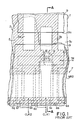
- a typical example of the solid-state image pick-up device is fabricated on a p-type silicon substrate 1.
- a thick oxide film 2 covers the entire surface of the silicon substrate 1, the thick oxide film 2 is partially removed from the silicon substrate 1 in Fig. 1 for better understanding.
- the silicon substrate 1 are formed a plurality of n-type rectangular regions NR1 arranged in staggered manner which provide photo-electric converting regions 3a, 3b and 3c together with p-type impurity regions PR1 overlapped therewith.
- Another n-type impurity region NR2 is formed in the silicon substrate 1, and is connectable to every other photo-electric converting region 3b through a p-type channel forming area of the silicon substrate 1.
- the n-type rectangular region 3b has an outlet subregion 4 which is contiguous to the channel forming area.
- the n-type rectangular regions NR1 and the n-type impurity region NR2 are surrounded by a heavily doped p-type channel stopper 5 which is hatched in the drawings so as to be easily discriminated from n-type impurity regions NR1 and NR2.
- a large number of gate electrodes 6a, 6b, 6c, 6d, 6e, 6f and 6g are provided over the n-type impurity region NR2, and each of the gate electrodes 6a to 6g is partially overlapped with those located on both sides thereof.
- a phase-one transferring clock signal CLK1 and a phase-two transferring clock signal CLK2 are selectively supplied to the gate electrodes 6a to 6g, and the n-type impurity region NR2 and the gate electrodes 6a to 6g as a whole constitute a multi-stage vertical shift register 7 of the CCD type.
- a strip of transfer gate electrode 8 extends over the channel forming areas, and is partially overlapped with the outlet subregion 4.
- a transfer signal TR is supplied to the transfer gate electrode 8, thereby allowing electric charges accumulated in the photo-electric converting region 3b to flow into the vertical shift register 7.
- the outlet subregion 4 beneath the transfer gate electrode 8 has a width W and a length L, and a problem inherent in the prior art solid-state image pick-up device will be hereinlater described in conjunction with the width W and the length L.
- the solid-state image pick-up device thus arranged is covered with a photo-shield plate 9, however, a slit 9a formed in the photo-shield plate 9 exposes the photo-electric converting regions 3a to 3c to photo radiation carrying images.
- the electric charges are conveyed from stage to stage in synchronism with the phase-one and phase-two clock signals CLK1 and CLK2, and are read out to the outside thereof as an image carrying signal through a horizontal shift register (not shown) in a case of area image pick-up device or directly in a case of linear image pick-up device.
- the prior art solid-state image pick-up device has a drawback in that after images tend to take place on a display unit supplied with the image carrying signal, and residual electric charges left in the outlet subregion 4 are causative of the after images.
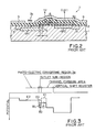
- the outlet subregion 4 and the associated channel forming area have the respective bottom edges E0 and E1 of the conduction bands indicated by broken lines, and the channel forming area provides a potential barrier against the electric charges accumulated in the photo-electric converting region 3b.
- the transfer signal TR goes up to the active high voltage level, the bottom edge E0 in the outlet subregion 4 becomes lower than the bottom edge E1 in the channel forming area indicated by real lines, and a potential well WL takes place in the outlet subregion 4.
- a narrow portion takes place in the n-type rectangular region NR1, and depletion regions extending from the p-type impurity region PR1 and the silicon substrate 1 deform the bottom edge in the narrow portion lower with respect to that in the outlet subregion 4 beneath the transfer gate electrode 8. This results in the potential barrier PB. Since the potential barrier PB blocks electric charges, the solid-state image pick-up device with the short length L also suffers from after images.
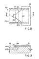
- FIGs. 7 and 8 shows an outlet subregion with a small width W, however, the thick oxide film 2 and the photo-shield plate 9 are removed from the solid-state image pick-up device. If the width W is decreased, the narrow outlet subregion 4 restricts the amount of electric charges passing therethrough, and all of the electric charges produced by photo radiation hardly diffuse over the narrow outlet subregion 4 into the vertical shift register 7 in the presence of the transfer signal TR of the active high voltage level. The residual electric charges in the photo-electric converting region 3b produce after images on an associated display unit.
- An outlet subregion 4 as wide as 10 microns as shown in Fig. 10A smoothly transfers electric charges, and the amount of after images is not increased even if the transfer signal TR is made short (see dots in Fig. 10C). However, since the wide outlet subregion 4 accumulates residual electric charges due to the potential well WL, the after images is maintained in a relatively high level. On the other hand, if the outlet subregion 4 is decreased to 5 microns as shown in Fig. 10B, the amount of after images is relatively small in so far as the transfer signal TR is equal to or greater than 1 microsecond. However, the amount of the after images is drastically increased in the presence of the transfer signal TR less than 1 microsecond (see bubbles in Fig. 10C).
- the present invention proposes to accelerate electric charges with electric field produced along an outlet subregion.
- a solid-state image pick-up device comprising a) a semiconductor substrate of a first conductivity type, b) a plurality of photo-electric converting regions having first impurity regions of a second conductivity type opposite to the first conductivity type, respectively, and formed in a surface portion of the semiconductor substrate at spacings, c) a shift register having a charge transfer region of the second conductivity type separated from the first impurity regions by respective channel forming regions of the first conductivity type, d) a thin insulating film covering the channel forming regions and outlet subregions of the first impurity regions, the outlet subregions being contiguous to the channel forming regions, respectively, and e) a transfer gate electrode extending on the thin insulating film and shaped in such a manner as to create an electric field over each outlet subregion and the associated channel forming region for accelerating carriers from aforesaid each outlet subregion through the associated channel forming region to the shift register.
- a solid-state image pick-up device embodying the present invention is fabricated on a lightly doped p-type silicon substrate 21.
- a thick oxide film 22 covers the entire surface of the silicon substrate 1, the thick oxide film 22 is partially removed from the silicon substrate 21 in Fig. 11 for better understanding.
- the thick oxide film 22 is perfectly removed in Figs. 12 and 13.
- n-type rectangular regions NR21 arranged in staggered manner which provide photo-electric converting regions 23a, 23b, 23c and 23d together with associated p-type impurity regions PR21 overlapped therewith as will be better seen from Figs. 12 and 13.
- Another n-type impurity region NR22 is formed in the silicon substrate 21, and is connectable to every other photo-electric converting region 23b/23d through a p-type channel forming area.
- the n-type impurity region NR22 serves as a charge transfer region.
- the n-type rectangular regions 23b and 23d have respective outlet subregions 24a and 24b, and the outlet subregions 24a and 24b are contiguous to the associated channel forming regions, respectively.
- the n-type rectangular regions NR21 and the n-type impurity region NR22 are surrounded by a heavily doped p-type channel stopper 25 which is hatched in the drawings so as to easily discriminated from n-type impurity regions NR21 and NR22.
- the n-type rectangular impurity regions NR21 serve as first impurity regions
- the p-type impurity region PR21 as a second impurity region.
- a large number of gate electrodes 26a, 26b, 26c, 26d, 26e, 26f, 26g and 26h are provided over the n-type impurity region NR22, and each of the gate electrodes 26a to 26h is partially overlapped with those located on both sides thereof.
- a phase-one transferring clock signal CLK1 and a phase-two transferring clock signal CLK2 are selectively supplied to the gate electrodes 26a to 26h, and the n-type impurity region NR22 and the gate electrodes 26a to 26h as a whole constitute a multi-stage vertical shift register 27 of the CCD type.
- the n-type rectangular impurity regions 23a and 23c have also respective outlet subregions and are associated with another vertical shift register, these outlet subregions and the vertical shift register are not shown in the drawings.
- the vertical shift registers are coupled to a horizontal shift register (not shown) in a case of area image pick-up device, and an image carrying signal is transferred from the photo-electric converting regions 23a to 23d through the vertical shift registers 27 and the horizontal shift register to an external device.
- the image carrying signal is transferred to an external device through onely one vertical shift register 27.
- the image carrying signal reproduces images on a display unit (not shown).
- a transfer gate electrode 8 extends over the p-type channel forming areas contiguous to the outlet subregions 24a and 24b, and has projections 28a and 28b overlapped with the outlet subregions 24a and24b, respectively.
- a transfer signal TR is supplied to the transfer gate electrode 28, and allows electric charges accumulated in the photo-electric converting region 23b and 23d to flow into the vertical shift register 27.
- each of the projections 28a and 28b projects from a boss portion 28c and is shaped into a trapezoidal configuration.
- Two parallel segments of the trapezoidal configuration are labeled with W1 and W2, respectively.
- the segment W2 is as long as the distance defined by the heavily doped channel stopper 25.
- the trapezoidal projection 28a or 28b causes a conductive channel to increase the width toward the vertical shift register 28, and narrow channel effect takes place in the conductive channel.
- Fig. 14 illustrates the narrow channel effect. If the channel width is increased from 3 microns to 10 microns, the potential of the conductive channel is increased from 2.5 volts to 4.0 volts in the presence of 5 volts at a gate electrode over the conductive channel.
- W1 and W2 are adjusted to about 3 microns and about 10 microns, respectively, and potential difference of about 1.5 volts takes place along the projection 28a or 28b in the presence of the transfer signal TR of about 5 volts.
- an electric field is produced over the outlet subregion 24a or 24b and the associated channel forming region, and the energy diagram is illustrated in Fig. 15.
- the oblique bottom edges E11 and E12 are representative of the electric field due to the narrow channel effect in the presence of the transfer signal TR of about 5 volts, and a potential discontinuity PD1 takes place therebetween.
- Electric charges EL produced by photo radiation are accelerated by the electric field, and the channel forming area allows a large amount of the electric charges to flow rather than the channel forming area of the prior art solid-state image pick-up device.
- the segment W1 is so small that a potential well WL can accumulate an extremely small amount of electric charges.
- the narrow segment W1 never leave electric charges, because the electric charges EL are accelerated in the presence of the electric field.
- the electric charges surely reaches the vertical shift register 27 while the transfer signal TR remains in the high voltage level of about 5 volts, and the solid-state image pick-up device surely improves the quality of images reproduced on the associated display unit.
- the solid-state image pick-up device thus arranged is covered with a photo-shield plate 29, and a slit 29a formed in the photo-shield plate 29 exposes the photo-electric converting regions 23a to 23d to photo radiation carrying images.
- the image pick-up operation carried out by the solid-state image pick-up device according to the present invention is similar to that of the prior art solid-state image pick-up device except for the amount of after images, and no further description is incorporated for the sake of simplicity.
- the ratio of W1 to W2 is regulated to a certain value for allowing the narrow channel phenomenon to take place.
- W2 is greater than 10 microns, the advantage of the present invention is hardly achieved, and, therefore, W2 is equal to or less than about 10 microns.
- W1 should be decreased for the narrow channel phenomenon. If W1 is 80 % of W2, the narrow channel phenomenon can be expected, and W1 may be decreased to the minimum dimension allowable through a lithographic process.
- W1 and W2 are adjusted to about 3 microns and about 8 microns, respectively.
- Figs. 16 and 17 an essential part of another solid-state image pick-up device embodying the present invention is illustrated, and is similar to the first embodiment except for a third p-type impurity region 31 formed through ion-implantation. For this reason, other regions and films are designated by the same references used in Figs. 12 and 13 without any detailed description.
- the third p-type impurity region 31 covers not only the outlet subregion 24a but also a part of the channel forming area, and two potential discontinuities PD2 and PD3 take place in the bottom edges of the conduction bands as shown in Fig. 18.
- the bottom edges of the conduction bands are representative of an electric field stronger than that of the first embodiment, and electric charges produced by photo radiation are accelerated by the strong electric field. This enhances the charge transfer efficiency of the channel forming area.
- the solid-state image pick-up device drastically reduces residual electric charges by virtue of the electric field created along the outlet subregion and the channel forming area, and after images are less liable to take place on a display unit.
Landscapes
- Solid State Image Pick-Up Elements (AREA)
- Transforming Light Signals Into Electric Signals (AREA)
- Facsimile Heads (AREA)
Applications Claiming Priority (2)
| Application Number | Priority Date | Filing Date | Title |
|---|---|---|---|
| JP123691/90 | 1990-05-14 | ||
| JP2123691A JP2697246B2 (ja) | 1990-05-14 | 1990-05-14 | 固体撮像素子 |
Publications (2)
| Publication Number | Publication Date |
|---|---|
| EP0457192A1 true EP0457192A1 (de) | 1991-11-21 |
| EP0457192B1 EP0457192B1 (de) | 1997-10-22 |
Family
ID=14866940
Family Applications (1)
| Application Number | Title | Priority Date | Filing Date |
|---|---|---|---|
| EP91107540A Expired - Lifetime EP0457192B1 (de) | 1990-05-14 | 1991-05-08 | Festkörperbildaufnahmevorrichtung zur Beschleunigung elektrischer Ladungen von der photoelektrischen Konvertierungsregion mittels elektrischem Feld zum Transferregister |
Country Status (3)
| Country | Link |
|---|---|
| EP (1) | EP0457192B1 (de) |
| JP (1) | JP2697246B2 (de) |
| DE (1) | DE69127995T2 (de) |
Cited By (3)
| Publication number | Priority date | Publication date | Assignee | Title |
|---|---|---|---|---|
| FR2704978A1 (fr) * | 1993-05-07 | 1994-11-10 | Thomson Csf Semiconducteurs | Dispositif à transfert de charges à grille d'étraînement. |
| EP1450410A3 (de) * | 2003-02-21 | 2006-04-12 | Matsushita Electric Industrial Co., Ltd. | Festkörperbildaufnahmevorrichtung, deren Verfahren zur Herstellung und CCD-Bildaufnahmevorrichtung mit Zwischenzeilenrasterübertragung |
| CN115361512A (zh) * | 2022-08-18 | 2022-11-18 | 中国电子科技集团公司第四十四研究所 | 低残留电荷ccd结构 |
Families Citing this family (1)
| Publication number | Priority date | Publication date | Assignee | Title |
|---|---|---|---|---|
| CN110996836B (zh) | 2017-07-27 | 2023-04-11 | 阿莱恩技术有限公司 | 用于通过光学相干断层扫描术来处理正畸矫正器的系统和方法 |
Citations (3)
| Publication number | Priority date | Publication date | Assignee | Title |
|---|---|---|---|---|
| EP0125732A1 (de) * | 1983-05-13 | 1984-11-21 | Koninklijke Philips Electronics N.V. | Ladungsverschiebeanordnung |
| EP0333260A1 (de) * | 1988-03-15 | 1989-09-20 | Koninklijke Philips Electronics N.V. | Ladungsgekoppelte Anordnung |
| EP0360595A2 (de) * | 1988-09-22 | 1990-03-28 | Matsushita Electronics Corporation | Festkörperbildsensor |
Family Cites Families (3)
| Publication number | Priority date | Publication date | Assignee | Title |
|---|---|---|---|---|
| JPS60119181A (ja) * | 1983-12-01 | 1985-06-26 | Nec Corp | 固体撮像装置 |
| JPS624362A (ja) * | 1985-07-01 | 1987-01-10 | Victor Co Of Japan Ltd | 固体撮像素子 |
| JPS6341071A (ja) * | 1986-08-06 | 1988-02-22 | Matsushita Electric Ind Co Ltd | 固体撮像素子 |
-
1990
- 1990-05-14 JP JP2123691A patent/JP2697246B2/ja not_active Expired - Fee Related
-
1991
- 1991-05-08 DE DE69127995T patent/DE69127995T2/de not_active Expired - Fee Related
- 1991-05-08 EP EP91107540A patent/EP0457192B1/de not_active Expired - Lifetime
Patent Citations (3)
| Publication number | Priority date | Publication date | Assignee | Title |
|---|---|---|---|---|
| EP0125732A1 (de) * | 1983-05-13 | 1984-11-21 | Koninklijke Philips Electronics N.V. | Ladungsverschiebeanordnung |
| EP0333260A1 (de) * | 1988-03-15 | 1989-09-20 | Koninklijke Philips Electronics N.V. | Ladungsgekoppelte Anordnung |
| EP0360595A2 (de) * | 1988-09-22 | 1990-03-28 | Matsushita Electronics Corporation | Festkörperbildsensor |
Non-Patent Citations (2)
| Title |
|---|
| PATENT ABSTRACTS OF JAPAN, vol. 10, no. 125 (E-402)[2182], 10th May 1986; & JP-A-60 257 574 (MATSUSHITA DENSHI KOGYO K.K.) 19-12-1985 * |
| PATENT ABSTRACTS OF JAPAN, vol. 12, no. 193 (E-617)[3040], 4th June 1988; & JP-A-62 296 463 (NEC CORP.) 23-12-1987 * |
Cited By (7)
| Publication number | Priority date | Publication date | Assignee | Title |
|---|---|---|---|---|
| FR2704978A1 (fr) * | 1993-05-07 | 1994-11-10 | Thomson Csf Semiconducteurs | Dispositif à transfert de charges à grille d'étraînement. |
| WO1994027322A1 (fr) * | 1993-05-07 | 1994-11-24 | Thomson-Csf Semiconducteurs Specifiques | Dispositif a transfert de charges a grille d'entrainement |
| US6091092A (en) * | 1993-05-07 | 2000-07-18 | Thomson-Csf Semiconducteurs Specifiques | Driving-gate charge-coupled device |
| EP1450410A3 (de) * | 2003-02-21 | 2006-04-12 | Matsushita Electric Industrial Co., Ltd. | Festkörperbildaufnahmevorrichtung, deren Verfahren zur Herstellung und CCD-Bildaufnahmevorrichtung mit Zwischenzeilenrasterübertragung |
| US7304286B2 (en) | 2003-02-21 | 2007-12-04 | Matsushita Electric Industrial Co., Ltd. | Solid-state imaging device, method for manufacturing the same and interline transfer CCD image sensor |
| CN115361512A (zh) * | 2022-08-18 | 2022-11-18 | 中国电子科技集团公司第四十四研究所 | 低残留电荷ccd结构 |
| CN115361512B (zh) * | 2022-08-18 | 2024-04-16 | 中国电子科技集团公司第四十四研究所 | 低残留电荷ccd结构 |
Also Published As
| Publication number | Publication date |
|---|---|
| JPH0423359A (ja) | 1992-01-27 |
| DE69127995D1 (de) | 1997-11-27 |
| DE69127995T2 (de) | 1998-05-20 |
| EP0457192B1 (de) | 1997-10-22 |
| JP2697246B2 (ja) | 1998-01-14 |
Similar Documents
| Publication | Publication Date | Title |
|---|---|---|
| US5517043A (en) | Split pixel interline transfer imaging device | |
| US4012759A (en) | Bulk channel charge transfer device | |
| JP2686914B2 (ja) | 線形固体撮像素子 | |
| WO1992010910A1 (en) | High resolution charge-coupled device (ccd) camera system | |
| US5196719A (en) | Solid-state image pick-up device having electric field for accelerating electric charges from photoelectric converting region to shift register | |
| US4236168A (en) | One-dimensional CCD sensor with overflow arrangement | |
| US6707495B1 (en) | Solid-state imaging device and a method of reading a signal charge in a solid-state imaging device which can reduce smear and can provide an excellent image characteristic | |
| US5365093A (en) | Solid-state imaging device with tapered channel regions | |
| EP0253330B1 (de) | Festkörperbildaufnahmeanordnung | |
| EP0457192B1 (de) | Festkörperbildaufnahmevorrichtung zur Beschleunigung elektrischer Ladungen von der photoelektrischen Konvertierungsregion mittels elektrischem Feld zum Transferregister | |
| US4649407A (en) | Charge coupled device for transferring electric charge | |
| EP0384286B1 (de) | Ladungsübertragungsvorrichtung, frei von Nachbildern auf Grund von elektrischen Restladungen | |
| US4901125A (en) | Charge coupled device capable of efficiently transferring charge | |
| US5066994A (en) | Image sensor | |
| US5294817A (en) | Output circuit for charged transfer device and having a high detection sensitivity | |
| JPH0666347B2 (ja) | 電荷結合装置 | |
| JPS60100477A (ja) | 放射線感応セミコンダクタ−装置 | |
| JPS6134263B2 (de) | ||
| JPS63313862A (ja) | 電荷転送装置 | |
| JPH0697416A (ja) | 固体撮像装置及びその製造方法 | |
| JPS61121582A (ja) | 固体撮像素子 | |
| JP2633240B2 (ja) | 固体撮像装置 | |
| JPH03116841A (ja) | 電荷結合素子 | |
| JPS6327057A (ja) | 固体撮像装置 | |
| JP2671151B2 (ja) | 半導体装置 |
Legal Events
| Date | Code | Title | Description |
|---|---|---|---|
| PUAI | Public reference made under article 153(3) epc to a published international application that has entered the european phase |
Free format text: ORIGINAL CODE: 0009012 |
|
| 17P | Request for examination filed |
Effective date: 19910508 |
|
| AK | Designated contracting states |
Kind code of ref document: A1 Designated state(s): DE FR GB NL |
|
| 17Q | First examination report despatched |
Effective date: 19950412 |
|
| GRAG | Despatch of communication of intention to grant |
Free format text: ORIGINAL CODE: EPIDOS AGRA |
|
| GRAH | Despatch of communication of intention to grant a patent |
Free format text: ORIGINAL CODE: EPIDOS IGRA |
|
| GRAH | Despatch of communication of intention to grant a patent |
Free format text: ORIGINAL CODE: EPIDOS IGRA |
|
| GRAA | (expected) grant |
Free format text: ORIGINAL CODE: 0009210 |
|
| RAP1 | Party data changed (applicant data changed or rights of an application transferred) |
Owner name: NEC CORPORATION |
|
| AK | Designated contracting states |
Kind code of ref document: B1 Designated state(s): DE FR GB NL |
|
| REF | Corresponds to: |
Ref document number: 69127995 Country of ref document: DE Date of ref document: 19971127 |
|
| ET | Fr: translation filed | ||
| PLBE | No opposition filed within time limit |
Free format text: ORIGINAL CODE: 0009261 |
|
| STAA | Information on the status of an ep patent application or granted ep patent |
Free format text: STATUS: NO OPPOSITION FILED WITHIN TIME LIMIT |
|
| 26N | No opposition filed | ||
| REG | Reference to a national code |
Ref country code: GB Ref legal event code: IF02 |
|
| REG | Reference to a national code |
Ref country code: GB Ref legal event code: 732E |
|
| NLS | Nl: assignments of ep-patents |
Owner name: NEC ELECTRONICS CORPORATION |
|
| REG | Reference to a national code |
Ref country code: FR Ref legal event code: TP |
|
| PGFP | Annual fee paid to national office [announced via postgrant information from national office to epo] |
Ref country code: NL Payment date: 20040505 Year of fee payment: 14 Ref country code: GB Payment date: 20040505 Year of fee payment: 14 |
|
| PGFP | Annual fee paid to national office [announced via postgrant information from national office to epo] |
Ref country code: FR Payment date: 20040510 Year of fee payment: 14 |
|
| PGFP | Annual fee paid to national office [announced via postgrant information from national office to epo] |
Ref country code: DE Payment date: 20040520 Year of fee payment: 14 |
|
| PG25 | Lapsed in a contracting state [announced via postgrant information from national office to epo] |
Ref country code: GB Free format text: LAPSE BECAUSE OF NON-PAYMENT OF DUE FEES Effective date: 20050508 |
|
| PG25 | Lapsed in a contracting state [announced via postgrant information from national office to epo] |
Ref country code: NL Free format text: LAPSE BECAUSE OF NON-PAYMENT OF DUE FEES Effective date: 20051201 Ref country code: DE Free format text: LAPSE BECAUSE OF NON-PAYMENT OF DUE FEES Effective date: 20051201 |
|
| GBPC | Gb: european patent ceased through non-payment of renewal fee |
Effective date: 20050508 |
|
| PG25 | Lapsed in a contracting state [announced via postgrant information from national office to epo] |
Ref country code: FR Free format text: LAPSE BECAUSE OF NON-PAYMENT OF DUE FEES Effective date: 20060131 |
|
| NLV4 | Nl: lapsed or anulled due to non-payment of the annual fee |
Effective date: 20051201 |
|
| REG | Reference to a national code |
Ref country code: FR Ref legal event code: ST Effective date: 20060131 |