EP0458260B1 - Bandantriebssystem - Google Patents
Bandantriebssystem Download PDFInfo
- Publication number
- EP0458260B1 EP0458260B1 EP91108174A EP91108174A EP0458260B1 EP 0458260 B1 EP0458260 B1 EP 0458260B1 EP 91108174 A EP91108174 A EP 91108174A EP 91108174 A EP91108174 A EP 91108174A EP 0458260 B1 EP0458260 B1 EP 0458260B1
- Authority
- EP
- European Patent Office
- Prior art keywords
- roller
- creep
- belt
- detecting means
- driving system
- Prior art date
- Legal status (The legal status is an assumption and is not a legal conclusion. Google has not performed a legal analysis and makes no representation as to the accuracy of the status listed.)
- Expired - Lifetime
Links
- 238000006073 displacement reaction Methods 0.000 claims abstract description 36
- 239000000835 fiber Substances 0.000 claims description 13
- 239000000463 material Substances 0.000 claims description 12
- 239000013598 vector Substances 0.000 claims description 10
- 238000004804 winding Methods 0.000 claims description 7
- 229920001971 elastomer Polymers 0.000 description 13
- 229920006231 aramid fiber Polymers 0.000 description 11
- 239000004760 aramid Substances 0.000 description 10
- 239000013013 elastic material Substances 0.000 description 7
- 238000012360 testing method Methods 0.000 description 7
- 239000004033 plastic Substances 0.000 description 6
- 229920003023 plastic Polymers 0.000 description 6
- 238000010276 construction Methods 0.000 description 5
- 230000003247 decreasing effect Effects 0.000 description 5
- 238000010586 diagram Methods 0.000 description 5
- 229910052751 metal Inorganic materials 0.000 description 4
- 239000002184 metal Substances 0.000 description 4
- 229920002943 EPDM rubber Polymers 0.000 description 3
- 229910052782 aluminium Inorganic materials 0.000 description 3
- XAGFODPZIPBFFR-UHFFFAOYSA-N aluminium Chemical compound [Al] XAGFODPZIPBFFR-UHFFFAOYSA-N 0.000 description 3
- UQSXHKLRYXJYBZ-UHFFFAOYSA-N Iron oxide Chemical compound [Fe]=O UQSXHKLRYXJYBZ-UHFFFAOYSA-N 0.000 description 2
- PXHVJJICTQNCMI-UHFFFAOYSA-N Nickel Chemical compound [Ni] PXHVJJICTQNCMI-UHFFFAOYSA-N 0.000 description 2
- 239000004677 Nylon Substances 0.000 description 2
- 238000004132 cross linking Methods 0.000 description 2
- 238000005470 impregnation Methods 0.000 description 2
- 239000000314 lubricant Substances 0.000 description 2
- 230000004048 modification Effects 0.000 description 2
- 238000012986 modification Methods 0.000 description 2
- 229920001778 nylon Polymers 0.000 description 2
- 229910052582 BN Inorganic materials 0.000 description 1
- PZNSFCLAULLKQX-UHFFFAOYSA-N Boron nitride Chemical compound N#B PZNSFCLAULLKQX-UHFFFAOYSA-N 0.000 description 1
- OKTJSMMVPCPJKN-UHFFFAOYSA-N Carbon Chemical compound [C] OKTJSMMVPCPJKN-UHFFFAOYSA-N 0.000 description 1
- 229920000049 Carbon (fiber) Polymers 0.000 description 1
- JOYRKODLDBILNP-UHFFFAOYSA-N Ethyl urethane Chemical compound CCOC(N)=O JOYRKODLDBILNP-UHFFFAOYSA-N 0.000 description 1
- 229930182556 Polyacetal Natural products 0.000 description 1
- 239000004698 Polyethylene Substances 0.000 description 1
- 229920006311 Urethane elastomer Polymers 0.000 description 1
- 238000005299 abrasion Methods 0.000 description 1
- 238000005452 bending Methods 0.000 description 1
- 239000004917 carbon fiber Substances 0.000 description 1
- 230000006835 compression Effects 0.000 description 1
- 238000007906 compression Methods 0.000 description 1
- 230000005489 elastic deformation Effects 0.000 description 1
- 239000000806 elastomer Substances 0.000 description 1
- 229910002804 graphite Inorganic materials 0.000 description 1
- 239000010439 graphite Substances 0.000 description 1
- 239000010687 lubricating oil Substances 0.000 description 1
- 229920002521 macromolecule Polymers 0.000 description 1
- 239000000203 mixture Substances 0.000 description 1
- CWQXQMHSOZUFJS-UHFFFAOYSA-N molybdenum disulfide Chemical compound S=[Mo]=S CWQXQMHSOZUFJS-UHFFFAOYSA-N 0.000 description 1
- 229910052982 molybdenum disulfide Inorganic materials 0.000 description 1
- 229910052759 nickel Inorganic materials 0.000 description 1
- 239000011368 organic material Substances 0.000 description 1
- 239000002985 plastic film Substances 0.000 description 1
- 229920006255 plastic film Polymers 0.000 description 1
- 229920000728 polyester Polymers 0.000 description 1
- -1 polyethylene Polymers 0.000 description 1
- 229920000573 polyethylene Polymers 0.000 description 1
- 229920006324 polyoxymethylene Polymers 0.000 description 1
- 230000002265 prevention Effects 0.000 description 1
- 239000011347 resin Substances 0.000 description 1
- 229920005989 resin Polymers 0.000 description 1
- HBMJWWWQQXIZIP-UHFFFAOYSA-N silicon carbide Chemical compound [Si+]#[C-] HBMJWWWQQXIZIP-UHFFFAOYSA-N 0.000 description 1
- 229910010271 silicon carbide Inorganic materials 0.000 description 1
- 239000007787 solid Substances 0.000 description 1
- RCYJPSGNXVLIBO-UHFFFAOYSA-N sulfanylidenetitanium Chemical compound [S].[Ti] RCYJPSGNXVLIBO-UHFFFAOYSA-N 0.000 description 1
- 230000004304 visual acuity Effects 0.000 description 1
Images




Classifications
-
- G—PHYSICS
- G03—PHOTOGRAPHY; CINEMATOGRAPHY; ANALOGOUS TECHNIQUES USING WAVES OTHER THAN OPTICAL WAVES; ELECTROGRAPHY; HOLOGRAPHY
- G03G—ELECTROGRAPHY; ELECTROPHOTOGRAPHY; MAGNETOGRAPHY
- G03G15/00—Apparatus for electrographic processes using a charge pattern
- G03G15/75—Details relating to xerographic drum, band or plate, e.g. replacing, testing
- G03G15/754—Details relating to xerographic drum, band or plate, e.g. replacing, testing relating to band, e.g. tensioning
- G03G15/755—Details relating to xerographic drum, band or plate, e.g. replacing, testing relating to band, e.g. tensioning for maintaining the lateral alignment of the band
-
- G—PHYSICS
- G03—PHOTOGRAPHY; CINEMATOGRAPHY; ANALOGOUS TECHNIQUES USING WAVES OTHER THAN OPTICAL WAVES; ELECTROGRAPHY; HOLOGRAPHY
- G03G—ELECTROGRAPHY; ELECTROPHOTOGRAPHY; MAGNETOGRAPHY
- G03G2215/00—Apparatus for electrophotographic processes
- G03G2215/00135—Handling of parts of the apparatus
- G03G2215/00139—Belt
- G03G2215/00143—Meandering prevention
- G03G2215/00151—Meandering prevention using edge limitations
Definitions
- the present invention relates to a belt driving system of the kind as referred to by the preamble of claim 1.
- a flat belt which includes photographic layer or dielectric layer thereon.
- the flat belt is wound round a plurality of parallel rollers so that the flat belt, instead of a photographic drum, performs as a photographic belt or a transcribing belt on the purpose of making the machine lightweighted and compacted.
- a base material of the flat belt used for the above usage is mostly material of less extension and high strength such as a plastic film and a metal leaf.
- elastic deformation of such belt is low. Accordingly, when the electrophotographic machine has errors such as dimensional errors of components, installing errors of rollers, unbalance of the belt tension, and uneven length of the belt, the belt cannot compensate such errors by its elasticity. Consequently, the flat belt creeps (moves laterally) to one side in the widthwise direction of the belt when it is running.
- Japanese Patent Publication Gazette Nos. 56-127501 and 59-205052 disclose a flat belt being provided with a guide for preventing creep
- No. 57-630347 discloses a flat belt which is provided with a restricting member in order to forcibly prevent the creep of the flat belt.
- Japanese Utility Model Registration Laying Open Gazette No. 58-110609 discloses one roller having a belt-position sensor as a creep detecting means for adjusting the creep.
- the belt-position sensor senses the creep of the belt
- the creep is adjusted by displacing the end of a creep adjusting roller.
- Japanese Utility Model Registration Laying Open Gazette No. 64-48457 discloses that when the flat belt creeps, a roller is moved in the direction of the rotating shaft, and the rotating shaft of the roller is moved by the movement of the roller. Thus, the creep is adjusted by moving the roller in the direction opposite to the creep.
- a guide or restricting member should be strong if a belt possesses large biasing force. Also, bending force resistance of the flat belt in the widthwise direction should be large and strength at the end of the belt should be high enough to avoid damages at side ends of the belt. Thus, the thicker the belt, the harder to apply the above embodiment. Moreover, the guide should be positioned accurately and forming the guide particularly in a seamless belt was hard.
- Such disadvantages are basically also to be found in a belt driving system of the kind as referred to by the preamble of claim 1 and disclosed for example in US-A-4 641 770.
- Such known belt driving system uses as a creep detecting means a disc which is arranged in the axis of a creep adjusting roller for rotating therewith and for being steadily held in contact with a lateral edge of the flat belt by means of a lever assembly which is biased by a compression spring that urges a disc-like roller which is supported for free rotation at a lever end towards said creep detecting disc.
- the creep detecting disc readily follows the lateral edge of the flat belt whereby its relative axial movement as caused by any creep of the flat belt is transmitted to said lever assembly which is designed such, that it finally causes a relocation of the creep adjusting roller such that the flat belt will then be moved opposite to its creeping direction.
- the present invention accordingly deals with the object of providing a belt driving system of the kind as referred in which any coming-up belt creep is counter-acted with more simple and at the same time more reliable and less expensive means.
- a belt driving system of the kind referred which in accordance with claim 1 has a creep detecting means which is supported axially immovable by an end of the creep adjusting roller and is rotatable independently therefrom; a roller-end displacing means is engaged with the creep detecting means such that any torque which is developed by the creep detecting means upon its contact with the flat belt when being moved in a creeping direction is converted into a movement for displacing the end of the creep adjusting roller towards a predetermined direction so as to incline the creep adjusting roller and to move the flat belt in a direction opposite to the creeping direction
- the creep detecting means will accordingly rotate by contact friction with the flat belt whenever the same comes into contact with the creep detecting means.
- the rotation of the creep detecting means is then converted into a displacement of the end of the roller for adjusting creep to a predetermined direction by the roller-end displacing means. If the end of the roller for adjusting the creep is displaced, a displacement in the direction opposite to the original creep is caused on the flat belt.
- the creep is adjusted.
- the flat belt is adjusted by being displaced at the end of the creep-adjusting roller according to the original creep. Therefore, stability of the flat belt and clear picture can be obtained if this belt driving system is applied to electrophotographic machine.
- FIG. 1-11 show a first embodiment, of which:
- Fig. 1 shows a belt driving system in the electrophotographic machine.
- reference numerals 1, 2, and 3 show the first, second, and third rollers, respectively.
- Each roller 1, 2, and 3 comprises a shaft member 1a, 2a, and 3a and a cylindrical portion 1b, 2b, and 3b, provided coaxially and rotatable integrally with each shaft member.
- Each cylinder portion 1b, 2b, and 3b is a size larger than the roller end and is formed essentially of a rubber such as EDPM cross-link rubber. It also could be any material such as resin and aluminum if it is not an elastic material.
- a photographic belt 4 having a photographic layer formed thereon performs as a flat belt in the present invention and is wound round the rollers 1, 2, and 3.
- the photographic belt 4 is used for the photographic material of an electrophotographic machine.
- Biaxial draw polyester is used for the base material of the photographic belt 4 and tension elasticity rate is set more than 200kg/mm 2 .
- the first roller 1 is connected to a driving motor 5 at the shaft member 1a, which means the first roller 1 is a drive roller.
- the second roller 2 is a driven roller and the axis of it is inclined with respect to the axis of the first roller 1, which means the end of the second roller 2 in direction A is displaced a little (for example, 1mm) to direction C with respect to the parallel line of the first roller.
- the third roller 3 is a creep adjusting roller and the axis of it is approximately parallel to the axis of the first roller 1.
- Springs 3c provided at the right and left ends of the third roller 3 possess supporting force for supporting the third roller 3 in the direction C. By this biasing force, tension of the photographic belt 4 is adjusted.
- a biasing means is formed by making the axis of the second roller 2 inclined with respect to the axis of the first roller 1.
- the end of the third roller 3 is, as shown in Figs. 2 and 3, supported rotatably by a lower frame 8a through a bush 7 which is a bearing member.
- This lower frame 8a engages with an upper frame 8b provided at a movable member 6 through a slide bearing 9.
- roller supporting member 8 for supporting an end of the third roller 3 movably toward a direction perpendicular to the axis of the roller is formed by the upper frame 8b, lower frame 8a, and the slide bearing 9.
- Creep detecting means 11 is supported coaxially with the third roller 3 and rotatably independently from the third roller 3 at the inner side of the lower frame 8a on the shaft member 3a of the third roller 3.
- a ring member 12 is mounted to an outer end, where the creep detecting means 11 is disposed, of the shaft member 3a.
- the above creep detecting means 11 is formed essentially of urethan elastomer and the like which has high friction coefficient between the surface of the photographic belt 4 and the creep detecting means 11 and has high friction resistency.
- the creep detecting means 11 is positioned close to the end of the cylinder portion 3b of the third roller 3 with a little space in between.
- the outer diameter of the creep detecting means 11 is the same as the outer diameter of the third roller 3 at the end facing the cylinder portion 3b of the third roller 3 and flares outwardly at the another end apart from the cylinder portion 3b, which means a surface 11a is tapered.
- the creep detecting means 11 is connected to one end of a string member 13 which is a windable means.
- This string member 13 is mounted to the fixed member S.
- the photographic belt 4 climbs the surface 11a and the creep detecting means 11 receives the torque.
- the string member 13 is wound into the creep detecting means 11 by its rotation.
- the end of the third roller 3 in the direction A is displaced in a direction which separates it from the end of the first roller 1 that is in the direction B in Fig. 1.
- the photographic belt 4 runs in the rotating direction of the third roller 3 wherein the third roller 3 is biased to the right with respect to the belt running direction. Then, the photographic belt 4 creeps in the direction opposite to the direction A.
- Roller-end displacing means 14 for displacing end of the third roller 3 in a given direction B when the creep detecting means 11 receives the torque is formed by the above construction.
- the photographic belt 4 runs, sliding to the direction contrary to the direction A.
- creeping force contrary to the original creeping force force in the direction A
- the end of the third roller 3 is displaced until the original creeping force is compensated.
- a spring 15 which is spring means is connected to the ring member 12 provided at the outer end of the shaft member 3a.
- This spring 15 biases the end of the third roller 3 in the direction opposite to the displacement caused by winding the string member 13.
- the displacement of the end of the third roller 3 is restricted within a predetermined level by this spring 15.
- a stopper 16 restricts the creep detecting means 11 to move to an outer side.
- the roller end of the third roller 3 where the creep detecting means 11 is positioned is displaced in the direction B by the winding of the string member 13.
- the photographic belt 4 runs, creeping in the direction opposite to the direction A by that displacement and therefore, displacement of the photographic belt 4 in the direction A is restricted.
- the spring 15 is extended by that displacement of the roller end and accordingly, biasing force is applied to the roller end of the third roller 3.
- the displacement of the third roller 3 is restricted and the side ends of the photographic belt 4 is kept within a confined area.
- creep of the photographic belt 4 is restricted, for example, to about 10 ⁇ m.
- the photographic belt 4 creeps in one direction first and that creep is compensated so that the creep is small. Consequently, stable running of the photographic belt 4 can be maintained and clear picture in the electrophotographic machine of the present invention can be maintained.
- the second roller is inclined with respect to the rollers 1 and 3 so that the photographic belt 4 creeps in the direction A.
- the third roller can be inclined with respect to the rollers 1 and 2 by the spring 15 in order to make photographic belt 4 creep in the direction A when the photographic belt 4 is not in contact with the creep detecting means 11.
- the string member 13 is used as a windable member at the roller-end displacing means 14.
- spiral spring can be used instead of it in order to eliminate the spring 15.
- an outer gear 21a instead of the string member 13, can be formed on an outer circumference of the creep detecting means 11 and the roller end is displaced by having the gear 21a mesh with a rack gear 22.
- friction force with a friction board 32 can be used for the string member 13 by raising friction coefficient of a part of the outer circumference of the creep detecting means 11.
- a rod 17, having one end thereof connected to a position spaced from the rotational center of the creep detecting means 11 and the other end connected to a fixed member S, can be used for the string member 13.
- a tapered surface 11a of the creep detecting means 11 is preferably formed for better transmitting the torque of the belt to the creep detecting means 11.
- this taper is not necessarily required, but the surface 11a can be a cylinder which has the same diameter of the third roller 3 all the way.
- the spring member 15 is used as spring means which biases the end of the third roller 3 in the direction opposite to the displacement caused by the roller-end displacing means 14.
- other means can be used if it accomplishes that object.
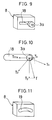
- the roller supporting member 8 of the present embodiment comprises a long hole 18, the roller end 3a of the third roller 3 extends therethrough.
- This long hole 18 extends to the direction in which the outer end of the shaft member 3a moves when the string member 13 is wound onto the creep detecting means 11. When the outer end of the shaft member 3a moves, the outer end moves inside the long hole 18.
- the tension vector T of the tension vectors T 1 and T 2 of the photographic belt 4 can be expressed by T X and T Y for X direction and Y direction as shown in Fig. 10.
- T X and T Y possess the following relationship: T X - ⁇ R T Y >0 where ⁇ R is a friction coefficient between the shaft member 3a and inner side of the long hole 18 and photographic belt 4 runs when the shaft member 3a is positioned as shown in Fig. 10.
- T X and T Y also possess the following relationship when the photographic belt 4 creeps and climbs the creep detecting means 11 and the creep detecting means 11 winds the string member 13, T MX - ⁇ S T Y > T X - ⁇ R T Y where T MX is a tension force of winding the string member in X direction by the torque of the creep detecting means 11 when the belt climbs the creep detecting means 11, and ⁇ S is a friction coefficient between the shaft member 3a and inner side of the long hole 18.
- roller end 3a moves to the left in Fig. 10 and adjusts the creep of the photographic belt 4.
- the outer end of the shaft member 3a of the third roller 3 extends through the long hole 18.
- the shaft member 3a moves along the long hole 18 and the shaft member 3a can be supported movably with simple construction, instead of using a slide bearing and the like.
- the friction coefficient of the inner side of this long hole 18 is preferably small and oilless bearing made of plastic including oil-impregnation plastic and lubricant plastic can be used for it.
- a long hole 19 projecting upwardly as shown in Fig. 11 or projecting downwardly can be used for a long hole 18.
- only one roller is used for adjusting creep.
- two rollers can be provided for that.
- the present invention is applied to the photographic belt of the electrophotographic machine.
- the present invention is applicable to other types of belt driving systems such as a driving system for a copying machine and flat belt driving system.
- the creep detecting means 11 is formed of oil-impregnation plastic, super macromolecule polyethylene, nylon, polyacetal, and a mixture of lubricating oil plastic and solid lubricant such as boron nitride, graphite, molybdenum disulfide, and titanium sulfide.
- a second embodiment of the present invention is described below. This embodiment relates to the creep detecting means 11.
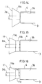
- the surface 11a of the creep detecting means 11 flares outwardly in a concaved curve to an increasing diameter at the end apart from the cylinder portion 3b of the third roller 3. That is, the end of the cylinder portion 3b of the third roller 3 is followed by the inner end of the surface 11a of the creep detecting means 11.
- the photographic belt 4 climbs the surface 11a, the photographic belt 4 does not bend on the boundary between the cylinder portion 3b and the creep detecting means 11 and accordingly, the longer service life of the photographic belt 4 can be obtained.
- the area of the belt on the creep detecting means 11 is large, the response for adjusting creep can be done quickly since the friction force between the photographic belt 4 and the surface 11a is increased.
- the surface 11a of the creep detecting means 11 can be formed in a range where the photographic belt 4 climbs.
- the end facing the cylinder portion 3b of the third roller 3, i. e., the vertical face of the creep detecting means 11 facing the cylinder portion 3b in Fig. 14, is a size smaller than the outer diameter of the third roller 3.
- the creep detecting means 11 of Fig. 15 has a column part 11b provided integrally at the inner side of the surface 11a.
- the diameter of this column part 11b is the same as the outer diameter of the third roller 3 and extends horizontally from end of the inner side of the surface 11a to the third roller 3.
- the creep detecting means 11 of Fig. 16 has column part 11c of a smaller diameter provided integrally at inner side of the surface 11a.
- the diameter of the column part 11c is smaller than the outer diameter of the third roller 3 and extends horizontally from the inner side of the surface 11a to the third roller 3.
- the side end of the photographic belt 4 is positioned to face the outer circumference of the column part 11c of a small diameter as shown by the continuous line in Fig. 16.
- the photographic belt 4 when the photographic belt 4 creeps, the photographic belt 4 is not rolled up in the space between the cylinder portion 3b and the creep detecting means 11.
- the system can be simplified since the space between the cylinder 3b and the photographic belt 4 does not request highly precise dimensional accuracy.
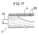
- cylinder portions 1b, 2b of the first and second rollers 1, 2 out of three rollers 1 ⁇ 3 includes a plurality of aramid fibers, the length of the aramid fibers is 1mm ⁇ 10mm. A part of each aramid fiber 20 is projecting outwardly 0.01 ⁇ 1.00mm in the radius direction of each cylinder portion 1b, 2b from the surface of that cylinder portion.
- the belt driving system operates, the cylinder portions 1b and 2b of the first and second rollers 1 and 2 do not contact the photographic belt 4 directly, but through the aramid fibers.
- aramid fibers 20 are mixed to ,the rubber when the cylinder portions 1b and 2b are formed, and thereafter the cylinder portions 1b and 2b are abraded.
- the friction coefficient between the cylinders 1b and 2b and the photographic belt 4 is set properly. When slip occurs between them, that slip is allowed and the photographic belt 4 and cylinders 1b and 2b are prevented from breaking. Moreover, since they do not contact with each other directly, surfaces of them are not affected by humidity and temperature. Thus, constant friction coefficient is obtained so that the running of the belt is stabilised. Furthermore, since fibers of high rigidity are in contact with the photographic belt 4, the holding power for cylinders 1b and 2b to hold the photographic belt 4 is high. The driving of the first roller is transmitted securely and stable running can be obtained thereby.
- the third roller 3 does not have aramid fibers 20, and the friction coefficient between the third roller 3 and the photographic belt 4 is set higher than that of the first and second rollers. Accordingly, creep adjusting of the third roller 3, i.e., displacement toward the direction contrary to the direction A of the photographic belt 4, can be carried out smoothly and securely.
- the projecting part a needlelike thing
- the projecting part can vary between 0.01 ⁇ 1.00mm according to the friction coefficient which is required by the system, belt, and rollers.
- the aramid fibers 20 are embedded on the cylinder portions 1b and 2b and the cylinder portions 1b and 2b are abraded to make the aramid fibers project from the surface.
- the aramid fibers 20 can be attached to the surface of the cylinder portions 1b and 2b directly.
- the short fibers are not limited to aramid fibers, however, other organic fibers (for example PET and Nylon), carbon fibers, and filar of no needle (for example, silicon carbide and iron oxide) can be used.
- organic fibers for example PET and Nylon
- carbon fibers for example, carbon fibers
- filar of no needle for example, silicon carbide and iron oxide
- the cylinder portions 1b and 2b of the first roller and second rollers 1 and 2 are formed essentially of a rubber which is abraded after 20% of weight part of short fibers are mixed.
- the cylinder 3b of the third roller 3 is formed essentially of only an elastic material, for example cross-linking rubber of EDPM.
- EDPM cross-linking rubber
- a material possessing high friction coefficient and low friction resistance for example a urethane rubber, can be used.
- the short fibers of organic material is mixed to the cylinder portions 1b and 2b of the first and second rollers 1 and 2 and the surfaces of the rollers are abraded so that the friction coefficient of the roller surface contacting with the belt surface is lowered as described hereinafter.
- the friction coefficient between the third roller 3 which is a creep adjusting roller and the photographic belt 4 is set larger than that between the other rollers 1 and 2 and the photographic belt 4.
- the cylinder portions 1b and 2b of the first and second rollers 1 and 2 are formed essentially of a rubber where short fibers are mixed therein, having the hard and abraded surface.
- the cylinder portion 3b of the third roller 3 is formed essentially of soft rubber.
- the friction coefficient between the third roller 3 and the photographic belt 4 is larger than that of the first and second rollers 1 and 2.
- Cylinder portions 1b ⁇ 3b of the rollers 1 ⁇ 3 are formed essentially of elastic materials in the present embodiment.
- cylinder portions 1b and 2b of the first and second rollers 1 and 2 can be formed essentially of metal and only the cylinder portion 3b of the third roller 3 is formed essentially of elastic material so that the friction coefficients with the photographic belt 4 are different.
- an object such as a carrier, toner, and a piece of paper in developer may stray in the back surface of the photographic belt 4 and consequently, the photographic belt 4 may be damaged.
- the cylinder portion 3b (surface of the roller contacting with the belt) of the third roller 3 is formed essentially of elastic material and short fibers are mixed in the cylinder portions 1b, 2b of the first and second rollers 1, 2, while surfaces, in contact with the belt, of the all three rollers 1 ⁇ 3 are formed essentially of elastic materials.
- the friction coefficient of the surface, in contact with the belt, of the third roller 3 is larger than that of the first and second rollers. This results in maintaining smooth creep adjusting and prevention of photographic belt 4 from being damaged.
- testing belt TBi is wound round the roller Ri, one end of the testing belt TBi is connected to a load cell Lc.
- Table 2 shows displacement of the creep adjusting roller and deformation in the widthwise direction of the belt in various combination of the belt and rollers.
- Nos. 1 and 2 are belts of the present invention and Nos. 3 ⁇ 6 are belts of comparable examples.
- A, B, and C mean EPDM rubber, Rubber mixed with short fibers, and aluminum in the above Table 1 respectively.
- belt width is 250mm
- belt length is 140mm
- belt tension which is biasing force of the spring 3c
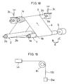
- the roller 3 is positioned rather on the second roller side than on the mid point between the first and the second rollers. That is, the rollers possess the following relationship: l 1 > l 2 where l 1 is a distance between the first roller 1 and the point P which is the crossing point of line X between the rollers 1 and 2 and the line perpendicular to the line X from the roller 3, and l 2 is a distance between the second roller 2 and the point P.
- the vector F which is tension T 1 between the photographic belt 4 and the first roller 1 at the position of the third roller 3 combined with tension T 2 between the photographic belt 4 and the second roller 2 at the position of the third roller 3, possesses component T X .
- This T X is opposite to the direction B of the displacement at the end of the third roller caused by the string member 13.
- the displacement at the end of the third roller 3 is restricted to be less than a predetermined level applied by the biasing force in the direction opposite to the displacement at the third roller 3 caused by the string member 13.
- the end, having the creep detecting means 11 thereon, of the third roller 3 is displaced by winding the string member 13.
- the creep of the photographic belt 4 in the direction A is restricted by that displacement. Since the vector F, which the tensions T 1 between the third roller 3 and the first roller 1 and T 2 between the third roller 3 and the second roller 2 are combined with, is applied in order to compensate the displacement of the roller-end, the displacement of the end of the third roller 3 is restricted by the balance between the winding force of the string member 13 and the biasing force of the combined vector F.
- the end of the photographic belt 4 is kept within a confined area. Consequently, running of the photographic belt 4 is stabilised and the creep of the photographic belt 4 is limited to about 10 ⁇ m.
- a spring may be provided.
- a spring and a bush for connecting the spring and the shaft member 3a will be required.
- the number of components can be reduced.
- the belt driving system of photographic belt has three rollers 1 ⁇ 3.
- a system having four or more rollers as shown in Fig. 21, which has four rollers R1-R4, can be used if the vector F, which the belt tensions T 1 and T 2 between the third roller R3 for adjusting creep and a pair of rollers R1 and R2 (the first and the second rollers) adjacent to the third roller 3 are combined with, possesses the component opposite to the direction B of the displacement caused by the string member 13. This will be clear by a comparison with Fig. 20.
- Figure 22 shows the relationship between the position of the rollers 1 ⁇ 3 and the displacement of the end of the third roller 3 caused by the roller-end displacing means 14.
- the direction of displacement caused by the roller-end displacing means 14 at the end of the third roller 3 is inclined outwardly at a predetermined angle, ⁇ (shown in alternate long and two short dashes line), with respect to the direction B (shown by the dotted line in the figure) between the first and second rollers. That is, the slide surface of the slide bearing 9 of Fig. 2 in the first embodiment is inclined (which is not shown in Fig. 22).
- Other structure is identical with the fifth embodiment.
- the component T X ' of the vector F opposite to the roller displacing direction is larger than that of the fifth embodiment (T X in the direction B).
- the vector F is a belt tension between the third roller 3 and the first roller 1 combined with the tension between the third roller 3 and the second roller 2. Accordingly, the biasing force against the displacement caused by the roller-end displacing means 14 at the end of the third roller 3 becomes larger. Consequently, the displacement of the shaft member 3a can be restricted to be small and creep detecting is improved.
Landscapes
- Physics & Mathematics (AREA)
- General Physics & Mathematics (AREA)
- Discharging, Photosensitive Material Shape In Electrophotography (AREA)
- Devices For Conveying Motion By Means Of Endless Flexible Members (AREA)
- General Details Of Gearings (AREA)
- Delivering By Means Of Belts And Rollers (AREA)
- Control Or Security For Electrophotography (AREA)
- Electrostatic Charge, Transfer And Separation In Electrography (AREA)
- Control Of Throttle Valves Provided In The Intake System Or In The Exhaust System (AREA)
- Valve Device For Special Equipments (AREA)
Claims (16)
- Riemenantriebssystem, bestehend aus einem flachen Riemen (4), der um eine Vielzahl von Rollen (1, 2, 3) herum geführt ist, von denen wenigstens eine Rolle eine Antriebsrolle (1) und wenigstens eine andere Rolle eine Schlupfeinstellrolle (3) für eine Einstellung der Bewegung des flachen Riemens entgegengesetzt zu einem Schlupf ist, der durch eine Vorspanneinrichtung (15) verursacht wird, welche den flachen Riemen in einer Schlupfrichtung (A) gegen eine Schlupferfassungseinrichtung (11) hin vorspannt, die an einem axialen Ende der Schlupfeinstellrolle (3) vorgesehen und mit einer Rollenende-Verschiebeeinrichtung (13, 14; 17; 21a, 22; 32) in Eingriff gehalten ist, mittels welcher die Schlupfeinstellrolle (3) für die Einstellbewegung des flachen Riemens (4) entgegengesetzt zu der Schlupfrichtung (A) geneigt wird,
dadurch gekennzeichnet, daß die Schlupferfassungseinrichtung (11) axial unbeweglich durch ein Ende der Schlupfeinstellrolle (3) abgestützt und unabhängig davon drehbar ist, und daß die Rollenende-Verschiebeeinrichtung (13, 14; 17; 21a, 22; 32) mit der Schlupferfassungseinrichtung (11) derart in Eingriff gehalten ist, daß jegliches Drehmoment, das durch die Schlupferfassungseinrichtung (11) bei ihrer Berührung mit dem flachen Riemen (4) entwickelt wird, wenn sie in der Schlupfrichtung (A) bewegt wird, in eine Bewegung zum Verschieben des Endes der Schlupfeinstellrolle (3) gegen eine vorbestimmte Richtung (B) umgewandelt wird, um die Schlupfeinstellrolle (3) schräg zu stellen und den flachen Riemen (4) in einer Richtung entgegengesetzt zu der Schlupfrichtung (A) zu bewegen. - Riemenantriebssystem nach Anspruch 1, bei welchem die Rollenende-Verschiebeinrichtung (14) ein wickelbares Glied (13) aufweist, von welchem ein Ende mit der Schlupferfassungseinrichtung (11) für ein Wickeln des wickelbaren Gliedes verbunden ist und das andere Ende mit einem festen Glied (5) verbunden ist.
- Riemenantriebssystem nach Anspruch 1, bei welchem die Rollenende-Verschiebeeinrichtung ein Zahnrad (21a) aufweist, welches an einem Teil des Außenumfangs der Schlupferfassungseinrichtung (11) ausgebildet und mit einer stationären Zahnstange (22) im Eingriff ist.
- Riemenantriebssystem nach einem der Ansprüche 1 bis 3, bei welchem Federmittel (15) vorgesehen sind für eine Vorspannung des einen Endes der Schlupfeinstellrolle (3) in einer Richtung entgegengesetzt zu der Verschiebung, die durch die Rollenende-Verschiebeeinrichtung (13, 14; 17; 21a, 22; 32) verursacht wird.
- Riemenantriebssystem nach einem der Ansprüche 1 bis 3, bei welchem die Vorspanneinrichtung durch die in Bezug auf die Antriebsrolle (1) geneigte Anordnung einer angetriebenen Rolle (2) der Vielzahl der Rollen ausgebildet ist.
- Riemenantriebssystem nach einem der Ansprüche 1 bis 3, bei welchem die Vorspanneinrichtung durch eine Anordnung der Schlupfeinstellrolle (3) geneigt in Bezug auf die Antriebsrolle (1) ausgebildet ist, wenn der flache Riemen (4) keine Berührung mit der Schlupferfassungseinrichtung (11) hat.
- Riemenantriebssystem nach einem der Ansprüche 1 bis 6, bei welchem die Zugelastizitätsrate des flachen Riemens (4) höher als 200 kg/mm2 ist.
- Riemenantriebssystem nach einem der Ansprüche 1 bis 7, bei welchem eine photographische Schicht auf einer Oberfläche des flachen Riemens (4) ausgebildet ist.
- Riemenantriebssystem nach einem der Ansprüche 1 bis 7, bei welchem eine dielektrische Schicht auf einer Oberfläche des flachen Riemens (4) ausgebildet ist.
- Riemenantriebssystem nach einem der Ansprüche 1 bis 9, bei welchem das Ende der Schlupfeinstellrolle (3) mit der Schlupferfassungseinrichtung (11) durch ein Rollenabstützglied (8) abgestützt ist, wobei das Rollenabstützglied (8) ein Langloch (18, 19) aufweist, welches in der Richtung (B) der Verschiebung verläuft, die durch die Rollenende-Verschiebeeinrichtung (13, 14; 17; 21a, 22; 32) verursacht wird, welche an dem Ende der Schlupfeinstellrolle (3) vorgesehen ist, das durch das Langloch hindurch verläuft.
- Riemenantriebssystem nach einem der Ansprüche 1 bis 10, bei welchem die Schlupferfassungseinrichtung (11) eine Oberfläche (11a) hat, die sich nach außen konisch erweitert zu einem sich vergrößernden Durchmesser an einem von der Schlupfeinstellrolle (3) beabstandeten Ende, wobei die Oberfläche (11a) für eine Berührung mit dem flachen Riemen vorgesehen ist, wenn er in der Schlupfrichtung (A) schlüpft.
- Riemenantriebssystem nach Anspruch 11, bei welchem ein Säulenteil (11b) mit demselben Durchmesser wie die Schlupfeinstellrolle (3) an einer Innenseite der Oberfläche (11a) der Schlupferfassungseinrichtung (11) ausgebildet ist und zu der Schlupfeinstellrolle (3) hin verläuft.
- Riemenantriebssystem nach einem der Ansprüche 1 bis 12, bei welchem wenigstens eine Rolle (1) der Vielzahl der Rollen (1, 2, 3) mit Ausnahme der Schlupfeinstellrolle (3) mit einer Vielzahl kurzer Fasern (20) versehen ist, die von der Oberfläche der einen Rolle (1) nach außen vorstehen.
- Riemenantriebssystem nach Anspruch 13, bei welchem die kurzen Fasern (20) eine vorstehende Länge von 0.01 bis 1.00 mm haben.
- Riemenantriebssystem nach Anspruch 1, bei welchem die Schlupfeinstellrolle (3) im wesentlichen aus einem in Berührung mit dem flachen Riemen (4) befindlichen Material ausgebildet ist, welches einen höheren Reibungskoeffizienten hat als die Oberflächenmaterialien der anderen Rollen (1, 2).
- Riemenantriebssystem nach einem der Ansprüche 1 bis 15, bei welchem die Schlupfeinstellrolle (3) derart angeordnet ist, daß ein Vektor (F) die Riemenspannung zwischen der Schlupfeinstellrolle (3) und der einen (1) eines Paares (1, 2) benachbarter Rollen in der Vereinigung mit einer Riemenspannung zwischen der Schlupfeinstellrolle (3) darstellt, und daß die andere (2) des Paares der benachbarten Rollen eine Komponente (Tx) entgegengesetzt zu der Rollenende-Verschiebung besitzt, die durch die Rollenende-Verschiebeeinrichtung (13, 14; 17, 21a, 22; 32) verursacht wird.
Applications Claiming Priority (12)
| Application Number | Priority Date | Filing Date | Title |
|---|---|---|---|
| JP13438090 | 1990-05-24 | ||
| JP134380/90 | 1990-05-24 | ||
| JP25291890A JPH0699055B2 (ja) | 1990-05-24 | 1990-09-21 | ベルト駆動装置 |
| JP252918/90 | 1990-09-21 | ||
| JP258498/90 | 1990-09-25 | ||
| JP2258498A JP2878424B2 (ja) | 1990-09-25 | 1990-09-25 | ベルト駆動装置 |
| JP2258497A JP2641609B2 (ja) | 1990-09-25 | 1990-09-25 | ベルト駆動装置 |
| JP258497/90 | 1990-09-25 | ||
| JP265922/90 | 1990-10-02 | ||
| JP2265922A JP2825635B2 (ja) | 1990-10-02 | 1990-10-02 | ベルト駆動装置 |
| JP10866990U JPH0732518Y2 (ja) | 1990-10-16 | 1990-10-16 | 蛇行検出装置 |
| JP108669/90U | 1990-10-16 |
Publications (3)
| Publication Number | Publication Date |
|---|---|
| EP0458260A2 EP0458260A2 (de) | 1991-11-27 |
| EP0458260A3 EP0458260A3 (en) | 1993-02-24 |
| EP0458260B1 true EP0458260B1 (de) | 1996-08-21 |
Family
ID=27552296
Family Applications (1)
| Application Number | Title | Priority Date | Filing Date |
|---|---|---|---|
| EP91108174A Expired - Lifetime EP0458260B1 (de) | 1990-05-24 | 1991-05-21 | Bandantriebssystem |
Country Status (4)
| Country | Link |
|---|---|
| US (1) | US5181888A (de) |
| EP (1) | EP0458260B1 (de) |
| AT (1) | ATE141697T1 (de) |
| DE (1) | DE69121466T2 (de) |
Families Citing this family (19)
| Publication number | Priority date | Publication date | Assignee | Title |
|---|---|---|---|---|
| GB9000716D0 (en) * | 1990-01-12 | 1990-03-14 | Drive Systems Ltd | Drive system |
| US5254045A (en) * | 1990-10-23 | 1993-10-19 | Bando Chemicals Industries, Ltd. | Flat belt driving device |
| JP3124375B2 (ja) * | 1992-06-16 | 2001-01-15 | キヤノン株式会社 | 加熱装置 |
| JP2761191B2 (ja) * | 1994-08-12 | 1998-06-04 | バンドー化学株式会社 | ベルト伝動方法及びベルト伝動装置 |
| JPH11100112A (ja) * | 1997-09-27 | 1999-04-13 | Ricoh Co Ltd | ベルト装置 |
| KR100234296B1 (ko) * | 1997-12-11 | 1999-12-15 | 윤종용 | 인쇄기용 감광 벨트 스티어링 장치 |
| DE10101131A1 (de) | 2000-02-09 | 2001-08-16 | Heidelberger Druckmasch Ag | Riementrieb |
| JP4366162B2 (ja) | 2003-09-19 | 2009-11-18 | キヤノン株式会社 | 画像形成装置 |
| US7211015B2 (en) * | 2004-04-05 | 2007-05-01 | The Gates Corporation | Belt installation tool |
| NL1026177C2 (nl) * | 2004-05-12 | 2005-11-15 | Csi Ind B V | Transportbaan. |
| US7204774B2 (en) * | 2004-05-17 | 2007-04-17 | Emerson Electric Co. | One-piece drive pulley and belt guide |
| EP2045666B1 (de) | 2007-10-02 | 2010-11-17 | Océ-Technologies B.V. | Vorrichtung und Verfahren zur Riemenlenkung |
| JP5396050B2 (ja) | 2007-10-02 | 2014-01-22 | オセ−テクノロジーズ ビーブイ | ベルトを操縦するための装置及び方法 |
| JP4766140B2 (ja) * | 2009-03-27 | 2011-09-07 | 富士ゼロックス株式会社 | 片寄補正装置、中間転写装置、転写装置および画像形成装置 |
| US8351831B2 (en) * | 2009-03-27 | 2013-01-08 | Fuji Xerox Co., Ltd. | Displacement correcting device, intermediate transfer device, transfer device, and image forming apparatus |
| US9039602B2 (en) * | 2011-07-01 | 2015-05-26 | Fujifilm Corporation | Endoscope propelling device |
| JP5819869B2 (ja) * | 2013-02-21 | 2015-11-24 | 京セラドキュメントソリューションズ株式会社 | ベルト駆動機構、ベルト駆動装置、及びプーリー |
| JP2015194657A (ja) * | 2014-03-31 | 2015-11-05 | 富士ゼロックス株式会社 | 画像形成装置、ベルト装置 |
| JP6178767B2 (ja) * | 2014-08-29 | 2017-08-09 | 京セラドキュメントソリューションズ株式会社 | 画像形成装置 |
Family Cites Families (13)
| Publication number | Priority date | Publication date | Assignee | Title |
|---|---|---|---|---|
| US1490196A (en) * | 1920-09-10 | 1924-04-15 | American Laundry Mach Co | Automatic apron-guide roll |
| US1846665A (en) * | 1928-04-13 | 1932-02-23 | Troy Laundry Machinery Co | Conveyer belt centering mechanism |
| US1842946A (en) * | 1930-03-14 | 1932-01-26 | Prins Henry | Belt control apparatus |
| US2008318A (en) * | 1934-12-01 | 1935-07-16 | John A Ziegler | Guide-roll |
| US2342863A (en) * | 1942-03-14 | 1944-02-29 | Rudolph F Hlavaty | Self-aligning pulley |
| US3407673A (en) * | 1966-05-19 | 1968-10-29 | Raymond J. Slezak | Belt tracking apparatus |
| US3944420A (en) * | 1974-05-22 | 1976-03-16 | Rca Corporation | Generation of permanent phase holograms and relief patterns in durable media by chemical etching |
| US4170175A (en) * | 1978-03-24 | 1979-10-09 | General Electric Company | Belt tracking system |
| US4286706A (en) * | 1979-06-19 | 1981-09-01 | Xerox Corporation | Belt tracking system |
| US4397538A (en) * | 1981-09-03 | 1983-08-09 | Xerox Corporation | Belt alignment system |
| JPH0732646B2 (ja) * | 1984-06-13 | 1995-04-12 | 井関農機株式会社 | 脱穀機の伝動装置 |
| US4641770A (en) * | 1985-04-26 | 1987-02-10 | Eastman Kodak Company | Angularly adjustable web-supporting steering roller |
| US4929219A (en) * | 1989-06-16 | 1990-05-29 | Emerson Electric Co. | Belt locator for locating a belt on a pulley |
-
1991
- 1991-05-21 AT AT91108174T patent/ATE141697T1/de not_active IP Right Cessation
- 1991-05-21 DE DE69121466T patent/DE69121466T2/de not_active Expired - Fee Related
- 1991-05-21 EP EP91108174A patent/EP0458260B1/de not_active Expired - Lifetime
- 1991-05-24 US US07/705,421 patent/US5181888A/en not_active Expired - Fee Related
Also Published As
| Publication number | Publication date |
|---|---|
| EP0458260A2 (de) | 1991-11-27 |
| EP0458260A3 (en) | 1993-02-24 |
| DE69121466T2 (de) | 1997-03-27 |
| DE69121466D1 (de) | 1996-09-26 |
| US5181888A (en) | 1993-01-26 |
| ATE141697T1 (de) | 1996-09-15 |
Similar Documents
| Publication | Publication Date | Title |
|---|---|---|
| EP0458260B1 (de) | Bandantriebssystem | |
| JPH11106081A (ja) | 電子写真装置の感光ベルト寄止め機構 | |
| US5254045A (en) | Flat belt driving device | |
| EP0696511A2 (de) | Führungsmechanismus für Drucker | |
| JPH0526314A (ja) | ベルト駆動装置 | |
| JP3105998B2 (ja) | ベルト駆動装置 | |
| JPH05107871A (ja) | 帯電装置 | |
| JPH11263469A (ja) | ベルト駆動装置 | |
| JP2825635B2 (ja) | ベルト駆動装置 | |
| JP2878424B2 (ja) | ベルト駆動装置 | |
| JPH04133931A (ja) | ベルト駆動装置 | |
| JPH0526315A (ja) | ベルト駆動装置 | |
| JP2545490Y2 (ja) | ベルト駆動装置 | |
| JP2868878B2 (ja) | ベルト駆動装置 | |
| CN1773392A (zh) | 图像形成装置 | |
| JPH0732518Y2 (ja) | 蛇行検出装置 | |
| JPH0544801A (ja) | ベルト駆動装置 | |
| JPH0518450A (ja) | ベルト駆動装置 | |
| JPH11270637A (ja) | ベルト駆動装置 | |
| JP2545494Y2 (ja) | ベルト駆動装置 | |
| JP2868874B2 (ja) | ベルト駆動装置 | |
| JPH04148746A (ja) | ベルト駆動装置 | |
| JPH0518449A (ja) | ベルト駆動装置 | |
| JPH0512433U (ja) | ベルト駆動装置 | |
| JPH07103292A (ja) | ベルト駆動装置 |
Legal Events
| Date | Code | Title | Description |
|---|---|---|---|
| PUAI | Public reference made under article 153(3) epc to a published international application that has entered the european phase |
Free format text: ORIGINAL CODE: 0009012 |
|
| AK | Designated contracting states |
Kind code of ref document: A2 Designated state(s): AT DE FR GB IT |
|
| PUAL | Search report despatched |
Free format text: ORIGINAL CODE: 0009013 |
|
| AK | Designated contracting states |
Kind code of ref document: A3 Designated state(s): AT DE FR GB IT |
|
| 17P | Request for examination filed |
Effective date: 19930726 |
|
| 17Q | First examination report despatched |
Effective date: 19940428 |
|
| GRAH | Despatch of communication of intention to grant a patent |
Free format text: ORIGINAL CODE: EPIDOS IGRA |
|
| GRAH | Despatch of communication of intention to grant a patent |
Free format text: ORIGINAL CODE: EPIDOS IGRA |
|
| GRAA | (expected) grant |
Free format text: ORIGINAL CODE: 0009210 |
|
| AK | Designated contracting states |
Kind code of ref document: B1 Designated state(s): AT DE FR GB IT |
|
| REF | Corresponds to: |
Ref document number: 141697 Country of ref document: AT Date of ref document: 19960915 Kind code of ref document: T |
|
| REF | Corresponds to: |
Ref document number: 69121466 Country of ref document: DE Date of ref document: 19960926 |
|
| ITF | It: translation for a ep patent filed | ||
| ET | Fr: translation filed | ||
| PLBE | No opposition filed within time limit |
Free format text: ORIGINAL CODE: 0009261 |
|
| STAA | Information on the status of an ep patent application or granted ep patent |
Free format text: STATUS: NO OPPOSITION FILED WITHIN TIME LIMIT |
|
| 26N | No opposition filed | ||
| PGFP | Annual fee paid to national office [announced via postgrant information from national office to epo] |
Ref country code: AT Payment date: 20010514 Year of fee payment: 11 |
|
| PGFP | Annual fee paid to national office [announced via postgrant information from national office to epo] |
Ref country code: GB Payment date: 20010516 Year of fee payment: 11 |
|
| REG | Reference to a national code |
Ref country code: GB Ref legal event code: IF02 |
|
| PG25 | Lapsed in a contracting state [announced via postgrant information from national office to epo] |
Ref country code: GB Free format text: LAPSE BECAUSE OF NON-PAYMENT OF DUE FEES Effective date: 20020521 Ref country code: AT Free format text: LAPSE BECAUSE OF NON-PAYMENT OF DUE FEES Effective date: 20020521 |
|
| GBPC | Gb: european patent ceased through non-payment of renewal fee |
Effective date: 20020521 |
|
| PGFP | Annual fee paid to national office [announced via postgrant information from national office to epo] |
Ref country code: FR Payment date: 20040510 Year of fee payment: 14 |
|
| PGFP | Annual fee paid to national office [announced via postgrant information from national office to epo] |
Ref country code: DE Payment date: 20040603 Year of fee payment: 14 |
|
| PG25 | Lapsed in a contracting state [announced via postgrant information from national office to epo] |
Ref country code: IT Free format text: LAPSE BECAUSE OF NON-PAYMENT OF DUE FEES;WARNING: LAPSES OF ITALIAN PATENTS WITH EFFECTIVE DATE BEFORE 2007 MAY HAVE OCCURRED AT ANY TIME BEFORE 2007. THE CORRECT EFFECTIVE DATE MAY BE DIFFERENT FROM THE ONE RECORDED. Effective date: 20050521 |
|
| PG25 | Lapsed in a contracting state [announced via postgrant information from national office to epo] |
Ref country code: DE Free format text: LAPSE BECAUSE OF NON-PAYMENT OF DUE FEES Effective date: 20051201 |
|
| PG25 | Lapsed in a contracting state [announced via postgrant information from national office to epo] |
Ref country code: FR Free format text: LAPSE BECAUSE OF NON-PAYMENT OF DUE FEES Effective date: 20060131 |
|
| REG | Reference to a national code |
Ref country code: FR Ref legal event code: ST Effective date: 20060131 |