EP0458639B1 - Procédé et dispositif de commande d'une servovalve - Google Patents
Procédé et dispositif de commande d'une servovalve Download PDFInfo
- Publication number
- EP0458639B1 EP0458639B1 EP91304690A EP91304690A EP0458639B1 EP 0458639 B1 EP0458639 B1 EP 0458639B1 EP 91304690 A EP91304690 A EP 91304690A EP 91304690 A EP91304690 A EP 91304690A EP 0458639 B1 EP0458639 B1 EP 0458639B1
- Authority
- EP
- European Patent Office
- Prior art keywords
- servo
- coil
- control
- normal
- amplifier
- Prior art date
- Legal status (The legal status is an assumption and is not a legal conclusion. Google has not performed a legal analysis and makes no representation as to the accuracy of the status listed.)
- Expired - Lifetime
Links
- 238000000034 method Methods 0.000 title claims description 20
- 230000005856 abnormality Effects 0.000 claims description 60
- 230000002159 abnormal effect Effects 0.000 claims description 32
- 238000001514 detection method Methods 0.000 claims description 20
- 239000000446 fuel Substances 0.000 claims description 14
- 230000004044 response Effects 0.000 claims description 8
- 238000000926 separation method Methods 0.000 claims description 5
- 230000003321 amplification Effects 0.000 claims 2
- 238000003199 nucleic acid amplification method Methods 0.000 claims 2
- 238000003745 diagnosis Methods 0.000 description 17
- 229920006395 saturated elastomer Polymers 0.000 description 13
- 230000006870 function Effects 0.000 description 6
- 238000012545 processing Methods 0.000 description 3
- 230000009471 action Effects 0.000 description 2
- 238000007796 conventional method Methods 0.000 description 1
- 230000001419 dependent effect Effects 0.000 description 1
- 238000012544 monitoring process Methods 0.000 description 1
- 238000010248 power generation Methods 0.000 description 1
- 230000008569 process Effects 0.000 description 1
- 230000009467 reduction Effects 0.000 description 1
- 230000002194 synthesizing effect Effects 0.000 description 1
- 230000008646 thermal stress Effects 0.000 description 1
- 238000012546 transfer Methods 0.000 description 1
Images




Classifications
-
- G—PHYSICS
- G05—CONTROLLING; REGULATING
- G05B—CONTROL OR REGULATING SYSTEMS IN GENERAL; FUNCTIONAL ELEMENTS OF SUCH SYSTEMS; MONITORING OR TESTING ARRANGEMENTS FOR SUCH SYSTEMS OR ELEMENTS
- G05B9/00—Safety arrangements
- G05B9/02—Safety arrangements electric
- G05B9/03—Safety arrangements electric with multiple-channel loop, i.e. redundant control systems
-
- Y—GENERAL TAGGING OF NEW TECHNOLOGICAL DEVELOPMENTS; GENERAL TAGGING OF CROSS-SECTIONAL TECHNOLOGIES SPANNING OVER SEVERAL SECTIONS OF THE IPC; TECHNICAL SUBJECTS COVERED BY FORMER USPC CROSS-REFERENCE ART COLLECTIONS [XRACs] AND DIGESTS
- Y10—TECHNICAL SUBJECTS COVERED BY FORMER USPC
- Y10T—TECHNICAL SUBJECTS COVERED BY FORMER US CLASSIFICATION
- Y10T137/00—Fluid handling
- Y10T137/8593—Systems
- Y10T137/86493—Multi-way valve unit
- Y10T137/86574—Supply and exhaust
- Y10T137/86582—Pilot-actuated
- Y10T137/86614—Electric
Definitions
- the control system for the triple-coil servo valve has been arranged in such a manner that the output from each of the controllers is supplied to each of the coils via the servo amplifier so as to control the triple-coil servo valve by the total ampere's turn of the coils. Therefore, in a case where there is a fault in any one of the three systems, the residual two systems compensate the faulty system to continue the desired operation. However, if there are faults in the two systems, a decision is made that the system has been tripped.
- triple-coil serve valve a structure, which is arranged in such a manner that its actuator is in the form of a tripled system, has been disclosed in "TRIPLE REDUNDANT ELECTROMECHANICAL LINEAR ACTUATOR AND METHOD"; US patent number 4,521,707.
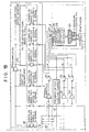
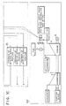
- the triple-coil servo valve 6 for bypass-controlling the flow rate of the fuel is controlled by a tripled system control system of a servo valve control apparatus 200, the tripled system control system being composed of a controller 7 of system A, a controller 8 of system B and a controller 9 of system C.
- a tripled system control system being composed of a controller 7 of system A, a controller 8 of system B and a controller 9 of system C.
- controllers 7, 8 and 9 carries out the same calculations.
- the operation of the servo valve 6 is controlled in accordance with the result of synthesizing the values obtained from the above-described calculations.
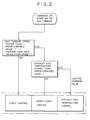
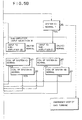
- the feedback value diagnosis portion 33 for diagnosing the servo coil electric current makes a comparison between the control command value 20 of the controller and a feedback value 47 of the servo coil electric current so as to diagnose the abnormality of the servo coil or the servo amplifier.
- the abnormality of the servo coil is exemplified by a disconnection of the servo coil.
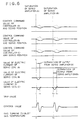
- the feedback value 47 of the coil electric current is zero.
- the feedback value 47 of the coil electric current is a saturated electric current value.
- the abnormality detection device 31 causes each of the controllers to diagnose the abnormality of each of the components in the control system, for example, the abnormality of the controller, that of the servo amplifier, that of the servo coil and that of the servo position detector.
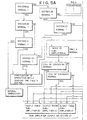
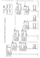
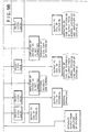
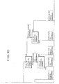
- the servo valve control apparatus 200 shown in Figs. 1A ⁇ 1C are arranged in such a manner that the abnormality of the controller, that of the servo amplifier, that caused from the disconnection of the servo coil and that of the servo position detector are detected of the abnormality detection device 31 of each of the controllers. Furthermore, servo amplifier output separation switches 35, 36 and 37 for omitting the faulty component from the operation of controlling the plant are provided. In addition, in order to effectively operate the normal systems, a compensating means comprising a sub-amplifier input selection switch 38, a sub-amplifier 39 and a sub-amplifier output selection switch 40 is provided.
- the output from the sub-amplifier 39 is transmitted to the system A, which is a system having the normal servo coil (in this state, although the output may be transmitted to the system A or B, an assumption is made that the output to the system A is made). Therefore, the electric current of the servo coil of the system A compensates the saturated electric current of the system B as well as the electric current of the servo coil of the system C when the servo amplifier of the system B is saturated. As a result, the continuation of the operation can be enabled safely.
- the servo amplifier is provided for each of the systems A, B and C.
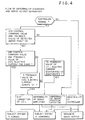
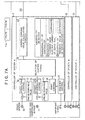
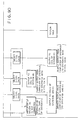
- the input at this time is performed in such a manner that the input of the normal controller is selected by the input switch 41. Then, a flow of the input performed in the amplifier of the system A will now be described with reference to Fig. 8.
- the amplifier of the system A selects the controller of the system A. In a case where the controller of the system A is abnormal, determinations whether or not the controller of the system B and that of the system C are sequentially made. As a result, the input of the normal controller is selected by the amplifier input switch 41.
- the amplifier of the system B similarly receives the control command value 20 of the normal controller after the determinations about the systems ⁇ B>, ⁇ C> and ⁇ A> have been sequentially made.
- the amplifier of the system C similarly receives the control command value 20 of the normal controller after the determinations about the systems ⁇ C>, ⁇ A> and ⁇ B> have been sequentially made.
- a 1-coil gain is selected by the gain switch 42 so that an output to the coil of the system A is made by the amplifier output switch 43. Subsequently, the amplifiers of the systems B and C are operated similarly.
Landscapes
- Physics & Mathematics (AREA)
- General Physics & Mathematics (AREA)
- Engineering & Computer Science (AREA)
- Automation & Control Theory (AREA)
- Safety Devices In Control Systems (AREA)
Claims (8)
- Dispositif pour commander une servo-vanne triple-bobine (6), la servo-vanne (6) comportant une unité de commande comprenant trois systèmes de commande (A, B, C), les composants de chaque système de commande incluantle dispositif comportant en outreun contrôleur (7, 8, 9) destiné à délivrer en sortie un signal d'instruction de commande (20) pour commander une grandeur d'état d'une installation conformément à une valeur prédéterminée,un servo-amplificateur (21, 22, 23) pour amplifier le signal d'instruction de commande (20) de manière à être capable de commander la servo-vanne triple-bobine (6), etune bobine (26, 27, 28) destinée à commander la servo-vanne (6) afin de faire correspondre la grandeur d'état au signal de commande amplifié,et dans lequel, durant un fonctionnement normal, lesdites trois bobines (26, 27, 28) commandent toutes la servo-vanne (6) en association les unes avec les autres,lesdits moyens de compensation pouvant agirdes moyens de détection d'anomalie (31) pour détecter une anomalie d'un composant de l'un quelconque des systèmes de commande (A, B, C),des moyens de séparation pour débrancher la sortie du servo-amplificateur ou contrôleur anormal, dans le cas où il est détecté qu'au moins un servo-amplificateur (21, 22, 23) ou contrôleur (7, 8, 9) est anormal, de la bobine du système de commande (A, B, C) correspondant, en réponse à la détection de l'anomalie, et caractérisé en ce qu'il comportedes moyens de compensation, pouvant agir en réponse aux moyens de détection d'anomalie et comportant un circuit de commutation (38, 40 ; 41, 43) pour commuter les connexions entre lesdits composants desdits systèmes de commande (A, B, C),le circuit de commutation pouvant agir pour commuter une connexion entre au moins un composant normal d'un système de commande anormal et un composant normal d'un autre système de commande au moins dans le cas où des composants anormaux sont détectés dans deux desdits systèmes de commande,(a) lorsqu'il est détecté que deux desdites bobines (26, 27, 28) sont anormales, pour ajuster le signal de commande envoyé vers la bobine normale restante afin de permettre un fonctionnement normal de la servo-vanne (6),
et(b) lorsqu'il est détecté que deux desdits servo-amplificateurs (21, 22, 23) sont anormaux, pour brancher ledit servo-amplificateur normal restant ou un servo-amplificateur auxiliaire (39) afin d'agir, de surcroít, sur la bobine normale (26, 27, 28) d'un système de commande (A, B, C) dans lequel le servo-amplificateur (21, 22, 23) est anormal, ou afin d'agir sur une seule bobine normale (26, 27, 28) avec un signal de commande amplifié. - Dispositif de régulation de débit de carburant comportant :une servo-vanne triple-bobine (6) pour une turbine à gaz (4),un dispositif selon la revendication 1 pour commander ladite servo-vanne (6),un moteur-couple (29) conçu pour être commandé par les bobines (26, 27, 28),un actionneur (24) conçu pour être entraíné par le moteur-couple (29), etun vanne de régulation de débit de carburant conçue pour être ouverte/fermée par l'actionneur (24),ladite grandeur d'état étant le degré d'ouverture de la vanne de régulation de débit de carburant.
- Dispositif selon la revendication 1 ou 2, dans lequel les moyens de compensation comportent un servo-amplificateur auxiliaire (39) et le circuit de commutation peut agir, en réponse à la détection d'une anomalie au sein du servo-amplificateur (21, 22, 23) de l'un desdits systèmes de commande (A, B, C), pour relier le contrôleur normal (7, 8, 9) de ce système de commande (A, B, C) au servo-amplificateur auxiliaire (39) et relier le servo-amplificateur auxiliaire (39) à une bobine normale de l'un desdits systèmes de commande (A, B, C).
- Dispositif selon la revendication 1 ou 2, dans lequel les moyens de compensation comportent des moyens (42) pour augmenter le gain du servo-amplificateur (21, 22, 2-3) d'un système normal restant parmi les systèmes de commande (A, B, C) en réponse à la détection d'une anomalie dans un autre des systèmes de commande (A, B, C) et au débranchement de celui-ci.
- Procédé pour commander une servo-vanne triple-bobine comportant trois systèmes de commande (A, B, C), les composants de chaque système de commande (A, B, C) incluantle procédé consistant en outre à :un contrôleur (7, 8, 9) destiné à délivrer en sortie un signal d'instruction de commande (20) pour commander une grandeur d'état d'une installation conformément à une valeur prédéterminée,un servo-amplificateur (21, 22, 23) pour amplifier le signal d'instruction de commande (20) de manière à être capable de commander la servo-vanne triple-bobine (6), etune bobine (26, 27, 28) destinée à commander la servo-vanne (6) afin de faire correspondre la grandeur d'état au signal de commande amplifié,et dans lequel, durant un fonctionnement normal, lesdites trois bobines (26, 27, 28) commandent toutes la servo-vanne (6) en association les unes avec les autres,détecter une anomalie d'un composant de l'un quelconque des systèmes de commande (A, B, C),séparer la sortie du servo-amplificateur ou contrôleur anormal, dans le cas où il est détecté qu'au moins un servo-amplificateur (21, 22, 23) ou contrôleur (7, 8, 9) est anormal, de la bobine du système de commande (A, B, C) correspondant en réponse à la détection de l'anomalie et étant caractérisé en ce qu'il consiste à :compenser, au moins en réponse à la détection d'une anomalie dans deux desdits systèmes de commande, en commutant une connexion entre au moins un composant normal d'un système de commande anormal et un composant normal d'un autre système de commande, et en ce que(a) lorsqu'il est détecté que deux desdites bobines (26, 27, 28) sont anormales, ajuster le signal de commande envoyé vers la bobine normale restante afin de permettre un fonctionnement normal de la servo-vanne (6),
et(b) lorsqu'il est détecté que deux desdits servo-amplificateurs (21, 22, 23) sont anormaux, brancher ledit servo-amplificateur normal restant ou un servo-amplificateur auxiliaire (39) afin d'agir, de surcroít, sur la bobine normale (26, 27, 28) d'un système de commande (A, B, C) dans lequel le servo-amplificateur (21, 22, 23) est anormal, ou afin d'agir sur une bobine normale unique (26, 27, 28) en utilisant un signal de commande amplifié. - Procédé selon la revendication 5, dans lequel la grandeur d'état est le degré d'ouverture d'une vanne de régulation de débit de carburant.
- Procédé selon la revendication 5 ou 6, dans lequel la compensation inclut l'amplification de l'un desdits signaux d'instruction de commande par un servo-amplificateur auxiliaire (39).
- Procédé selon la revendication 5 ou 6, dans lequel la compensation inclut l'amplification de l'un desdits signaux d'instruction de commande en modifiant le gain d'un servo-amplificateur (21, 22, 23).
Applications Claiming Priority (3)
| Application Number | Priority Date | Filing Date | Title |
|---|---|---|---|
| JP13480190 | 1990-05-24 | ||
| JP13480190 | 1990-05-24 | ||
| JP134801/90 | 1990-05-24 |
Publications (3)
| Publication Number | Publication Date |
|---|---|
| EP0458639A2 EP0458639A2 (fr) | 1991-11-27 |
| EP0458639A3 EP0458639A3 (en) | 1993-06-02 |
| EP0458639B1 true EP0458639B1 (fr) | 1999-08-04 |
Family
ID=15136848
Family Applications (1)
| Application Number | Title | Priority Date | Filing Date |
|---|---|---|---|
| EP91304690A Expired - Lifetime EP0458639B1 (fr) | 1990-05-24 | 1991-05-23 | Procédé et dispositif de commande d'une servovalve |
Country Status (3)
| Country | Link |
|---|---|
| US (1) | US5214913A (fr) |
| EP (1) | EP0458639B1 (fr) |
| DE (1) | DE69131495T2 (fr) |
Families Citing this family (7)
| Publication number | Priority date | Publication date | Assignee | Title |
|---|---|---|---|---|
| US5757641A (en) * | 1995-07-03 | 1998-05-26 | General Electric Company | Triplex control system with sensor failure compensation |
| US6003811A (en) * | 1997-03-24 | 1999-12-21 | The Boeing Company | Aircraft servovalve current rate limiter |
| EP1078729A1 (fr) * | 1999-08-25 | 2001-02-28 | Engel Maschinenbau Gesellschaft Mbh | Machine de moulage par injection avec moyens pour déceler une défaillance d'un capteur |
| US6508054B2 (en) * | 2000-05-31 | 2003-01-21 | Hitachi, Ltd. | Control system for servo valve and combined-cycle electric-power generating plant and gas turbine plant |
| GB0120004D0 (en) * | 2001-08-16 | 2001-10-10 | Lucas Industries Ltd | Hydraulic valve arrangement |
| US8698486B2 (en) | 2011-09-16 | 2014-04-15 | General Electric Company | Methods and systems for use in checking the polarity of multi-coil servos |
| CN107561438B (zh) * | 2016-06-30 | 2019-11-22 | 江苏核电有限公司 | 一种柴油机调速器油门开度正确性检查方法 |
Family Cites Families (12)
| Publication number | Priority date | Publication date | Assignee | Title |
|---|---|---|---|---|
| US3054039A (en) * | 1957-09-05 | 1962-09-11 | Meredith Dennis Lello | Plural channel servo systems |
| US3469162A (en) * | 1965-04-13 | 1969-09-23 | Hawker Siddeley Dynamics Ltd | Multiplex-type control apparatus |
| US3437312A (en) * | 1966-11-01 | 1969-04-08 | Bell Aerospace Corp | Electrical signal and monitoring apparatus for redundant control system |
| US3875390A (en) * | 1970-07-09 | 1975-04-01 | Secr Defence Brit | On-line computer control system |
| US4105900A (en) * | 1977-02-16 | 1978-08-08 | The Boeing Company | Signal selection apparatus for redundant signal sources |
| US4521707A (en) * | 1983-12-12 | 1985-06-04 | The Boeing Company | Triple redundant electromechanical linear actuator and method |
| US4608820A (en) * | 1985-05-03 | 1986-09-02 | Chandler Evans Inc. | Dual stepper motor actuator for fuel metering valve |
| US4752869A (en) * | 1985-05-09 | 1988-06-21 | Westinghouse Electric Corp. | Auxiliary reactor protection system |
| US4843537A (en) * | 1986-07-04 | 1989-06-27 | Hitachi, Ltd. | Control system |
| DE3637238A1 (de) * | 1986-11-03 | 1988-05-05 | Siemens Ag | Digitale 2 von 3-auswahl- und ausgabeschaltung |
| JPH0731537B2 (ja) * | 1987-09-11 | 1995-04-10 | 株式会社日立製作所 | 多重化制御装置 |
| DE3825280A1 (de) * | 1988-07-26 | 1990-02-01 | Bayerische Motoren Werke Ag | Steuersystem fuer stelleinrichtungen eines kraftfahrzeugs |
-
1991
- 1991-05-22 US US07/704,139 patent/US5214913A/en not_active Expired - Lifetime
- 1991-05-23 EP EP91304690A patent/EP0458639B1/fr not_active Expired - Lifetime
- 1991-05-23 DE DE69131495T patent/DE69131495T2/de not_active Expired - Fee Related
Also Published As
| Publication number | Publication date |
|---|---|
| DE69131495T2 (de) | 2000-03-23 |
| EP0458639A3 (en) | 1993-06-02 |
| DE69131495D1 (de) | 1999-09-09 |
| US5214913A (en) | 1993-06-01 |
| EP0458639A2 (fr) | 1991-11-27 |
Similar Documents
| Publication | Publication Date | Title |
|---|---|---|
| US3665809A (en) | Multiple channel redundant control system | |
| US20110290938A1 (en) | Actuator control apparatus | |
| EP0458639B1 (fr) | Procédé et dispositif de commande d'une servovalve | |
| US4440715A (en) | Method of controlling nuclear power plant | |
| US4664870A (en) | Testable voted logic power interface | |
| JP2003148108A (ja) | サーボ弁システム及びその動作方法 | |
| JP2684866B2 (ja) | サーボ弁の制御方法 | |
| US6616121B2 (en) | Control system for servo valve and control method therefor, and combined-cycle electric-power generating plant and gas turbine plant | |
| JP4688840B2 (ja) | 複数コイルサーボ弁の制御装置 | |
| US4436018A (en) | Multiple loop control system | |
| JPH045201B2 (fr) | ||
| JP2000018145A (ja) | 水力発電所の調速機及びその運転方法 | |
| JP2501166B2 (ja) | 発電所のタ―ビン制御装置 | |
| JP2005105912A (ja) | 複数コイルサーボ弁の制御装置 | |
| JP4802834B2 (ja) | サーボ弁制御回路 | |
| WO2022113345A1 (fr) | Dispositif de commutation de commande | |
| JP2539514B2 (ja) | ボイラ給水制御装置 | |
| JP2907930B2 (ja) | 原子力プラントの安全保護装置 | |
| JPH10222203A (ja) | ディジタル制御装置 | |
| JPS6213121Y2 (fr) | ||
| KR19980024802A (ko) | 펌프 선택 논리 회로 | |
| JP2730372B2 (ja) | タービン制御装置 | |
| WO2026074850A1 (fr) | Dispositif d'évaluation de défaillance, procédé d'évaluation de défaillance et programme associé | |
| JPS63140305A (ja) | 制御保護装置 | |
| JPH0563801B2 (fr) |
Legal Events
| Date | Code | Title | Description |
|---|---|---|---|
| PUAI | Public reference made under article 153(3) epc to a published international application that has entered the european phase |
Free format text: ORIGINAL CODE: 0009012 |
|
| AK | Designated contracting states |
Kind code of ref document: A2 Designated state(s): CH DE FR GB IT LI |
|
| PUAL | Search report despatched |
Free format text: ORIGINAL CODE: 0009013 |
|
| AK | Designated contracting states |
Kind code of ref document: A3 Designated state(s): CH DE FR GB IT LI |
|
| 17P | Request for examination filed |
Effective date: 19930707 |
|
| 17Q | First examination report despatched |
Effective date: 19941227 |
|
| GRAG | Despatch of communication of intention to grant |
Free format text: ORIGINAL CODE: EPIDOS AGRA |
|
| GRAG | Despatch of communication of intention to grant |
Free format text: ORIGINAL CODE: EPIDOS AGRA |
|
| GRAH | Despatch of communication of intention to grant a patent |
Free format text: ORIGINAL CODE: EPIDOS IGRA |
|
| GRAH | Despatch of communication of intention to grant a patent |
Free format text: ORIGINAL CODE: EPIDOS IGRA |
|
| GRAA | (expected) grant |
Free format text: ORIGINAL CODE: 0009210 |
|
| AK | Designated contracting states |
Kind code of ref document: B1 Designated state(s): CH DE FR GB IT LI |
|
| REG | Reference to a national code |
Ref country code: CH Ref legal event code: EP |
|
| REF | Corresponds to: |
Ref document number: 69131495 Country of ref document: DE Date of ref document: 19990909 |
|
| ITF | It: translation for a ep patent filed | ||
| ET | Fr: translation filed | ||
| REG | Reference to a national code |
Ref country code: CH Ref legal event code: NV Representative=s name: TROESCH SCHEIDEGGER WERNER AG |
|
| PLBE | No opposition filed within time limit |
Free format text: ORIGINAL CODE: 0009261 |
|
| STAA | Information on the status of an ep patent application or granted ep patent |
Free format text: STATUS: NO OPPOSITION FILED WITHIN TIME LIMIT |
|
| 26N | No opposition filed | ||
| REG | Reference to a national code |
Ref country code: GB Ref legal event code: IF02 |
|
| PGFP | Annual fee paid to national office [announced via postgrant information from national office to epo] |
Ref country code: CH Payment date: 20080401 Year of fee payment: 18 Ref country code: DE Payment date: 20080606 Year of fee payment: 18 |
|
| PGFP | Annual fee paid to national office [announced via postgrant information from national office to epo] |
Ref country code: IT Payment date: 20080423 Year of fee payment: 18 |
|
| PGFP | Annual fee paid to national office [announced via postgrant information from national office to epo] |
Ref country code: GB Payment date: 20080424 Year of fee payment: 18 |
|
| REG | Reference to a national code |
Ref country code: CH Ref legal event code: PL |
|
| GBPC | Gb: european patent ceased through non-payment of renewal fee |
Effective date: 20090523 |
|
| PG25 | Lapsed in a contracting state [announced via postgrant information from national office to epo] |
Ref country code: CH Free format text: LAPSE BECAUSE OF NON-PAYMENT OF DUE FEES Effective date: 20090531 Ref country code: LI Free format text: LAPSE BECAUSE OF NON-PAYMENT OF DUE FEES Effective date: 20090531 |
|
| REG | Reference to a national code |
Ref country code: FR Ref legal event code: ST Effective date: 20100129 |
|
| PG25 | Lapsed in a contracting state [announced via postgrant information from national office to epo] |
Ref country code: FR Free format text: LAPSE BECAUSE OF NON-PAYMENT OF DUE FEES Effective date: 20090602 |
|
| PGFP | Annual fee paid to national office [announced via postgrant information from national office to epo] |
Ref country code: FR Payment date: 20080423 Year of fee payment: 18 |
|
| PG25 | Lapsed in a contracting state [announced via postgrant information from national office to epo] |
Ref country code: GB Free format text: LAPSE BECAUSE OF NON-PAYMENT OF DUE FEES Effective date: 20090523 |
|
| PG25 | Lapsed in a contracting state [announced via postgrant information from national office to epo] |
Ref country code: DE Free format text: LAPSE BECAUSE OF NON-PAYMENT OF DUE FEES Effective date: 20091201 |
|
| PG25 | Lapsed in a contracting state [announced via postgrant information from national office to epo] |
Ref country code: IT Free format text: LAPSE BECAUSE OF NON-PAYMENT OF DUE FEES Effective date: 20090523 |