EP0459153A2 - Dispositif d'affichage à fibres optiques, dispositif de fixation pour les fibres optiques utilisées et fibres optiques decoratives utilisables dans ledit dispositif d'affichage - Google Patents
Dispositif d'affichage à fibres optiques, dispositif de fixation pour les fibres optiques utilisées et fibres optiques decoratives utilisables dans ledit dispositif d'affichage Download PDFInfo
- Publication number
- EP0459153A2 EP0459153A2 EP91106791A EP91106791A EP0459153A2 EP 0459153 A2 EP0459153 A2 EP 0459153A2 EP 91106791 A EP91106791 A EP 91106791A EP 91106791 A EP91106791 A EP 91106791A EP 0459153 A2 EP0459153 A2 EP 0459153A2
- Authority
- EP
- European Patent Office
- Prior art keywords
- optical fiber
- ferrule
- optical fibers
- display panel
- sleeve member
- Prior art date
- Legal status (The legal status is an assumption and is not a legal conclusion. Google has not performed a legal analysis and makes no representation as to the accuracy of the status listed.)
- Granted
Links
Images



Classifications
-
- G—PHYSICS
- G09—EDUCATION; CRYPTOGRAPHY; DISPLAY; ADVERTISING; SEALS
- G09F—DISPLAYING; ADVERTISING; SIGNS; LABELS OR NAME-PLATES; SEALS
- G09F9/00—Indicating arrangements for variable information in which the information is built-up on a support by selection or combination of individual elements
- G09F9/30—Indicating arrangements for variable information in which the information is built-up on a support by selection or combination of individual elements in which the desired character or characters are formed by combining individual elements
- G09F9/305—Indicating arrangements for variable information in which the information is built-up on a support by selection or combination of individual elements in which the desired character or characters are formed by combining individual elements being the ends of optical fibres
-
- G—PHYSICS
- G02—OPTICS
- G02B—OPTICAL ELEMENTS, SYSTEMS OR APPARATUS
- G02B6/00—Light guides; Structural details of arrangements comprising light guides and other optical elements, e.g. couplings
- G02B6/0001—Light guides; Structural details of arrangements comprising light guides and other optical elements, e.g. couplings specially adapted for lighting devices or systems
- G02B6/0005—Light guides; Structural details of arrangements comprising light guides and other optical elements, e.g. couplings specially adapted for lighting devices or systems the light guides being of the fibre type
- G02B6/0008—Light guides; Structural details of arrangements comprising light guides and other optical elements, e.g. couplings specially adapted for lighting devices or systems the light guides being of the fibre type the light being emitted at the end of the fibre
-
- G—PHYSICS
- G02—OPTICS
- G02B—OPTICAL ELEMENTS, SYSTEMS OR APPARATUS
- G02B6/00—Light guides; Structural details of arrangements comprising light guides and other optical elements, e.g. couplings
- G02B6/24—Coupling light guides
- G02B6/36—Mechanical coupling means
- G02B6/3628—Mechanical coupling means for mounting fibres to supporting carriers
- G02B6/3632—Mechanical coupling means for mounting fibres to supporting carriers characterised by the cross-sectional shape of the mechanical coupling means
- G02B6/3644—Mechanical coupling means for mounting fibres to supporting carriers characterised by the cross-sectional shape of the mechanical coupling means the coupling means being through-holes or wall apertures
Definitions
- the present invention relates to a display apparatus utilizing optical fibers, and a fixing device for an optical fiber used in such a display apparatus.
- the present invention also relates to a decorative optical fiber which may be advantageously utilized when the display apparatus is constituted as a decorative illumination such as a chandelier.
- an optical fiber display apparatus a plurality of optical fibers are implanted in a display panel in such a manner that an end face of each optical fiber is exposed on a display surface of the panel.
- the other end faces of the optical fibers are optically connected to a light source, so that a light guided from the light source through each optical fiber is emitted from the exposed end face thereof, whereby images, characters, marks, symbols or the like can be displayed on the display surface of the panel.
- This optical fiber display apparatus has many advantages or merits in comparison with another display apparatus.
- the optical fiber display apparatus can provide a very large display area which cannot be realized by a cathode-ray tube (CRT) display.
- maintenance of the optical fiber display apparatus is easier than that of an LED large size display apparatus having a display panel on which a plurality of light emitting devices (LED) are mounted.
- LED light emitting devices
- the optical fibers in the display panel are implanted by inserting the optical fibers through holes formed in the display panel, an adhesive is applied to a location at which each optical fiber is inserted, and after the adhesive has hardened, the exposed end faces of the implanted optical fibers are polished by a suitable abrasive machine or tool.
- the display apparatus may be constituted as a decorative illumination, such as a chandelier, by extending and suspending the optical fibers from the display surface of the panel.
- a decorative illumination such as a chandelier
- the disadvantages as mentioned above are substantially the same for the decorative illumination.
- the suspended optical fibers are frequently notched so that light leaks out of the notches of each optical fiber, resulting in increase of an optically decorative effect of the optical fibers.
- the conventionally notched or decorative optical fibers do not sufficiently increase the optically decorative effect, because the notches are formed as a V-shaped groove. Namely, the V-shaped groove must be shallow, to prevent a breaking of the decorative optical fiber, as much as possible, at the notched location. That is, if the notches are deeply formed in the optical fibers, to thereby increase the optically decorative effect thereof, these decorative optical fibers are very easily broken.
- an object of the present invention is to provide an optical fiber display apparatus wherein a plurality of optical fibers can be easily implanted in a display panel without the using of an adhesive, and wherein a broken and implanted optical fiber can be easily and quickly exchanged for a new one.
- Another object of the present invention is to provide a fixing device for an optical fiber used in the display apparatus, by which an easy implanting of the optical fiber and exchange of a broken optical fiber for a new one can be carried out.
- Yet another object of the present invention is to provide a decorative optical fiber used in a decorative illumination, in which openings are formed to leak sufficient light out of each of the openings, to thereby increase an optically decorative effect in such a manner that the decorative optical fiber is made as nonsusceptible to breakage as possible.
- an optical fiber display apparatus comprising: a display panel; a plurality of optical fibers, one end of each being optically connected to a light source and the other end thereof being implanted in the display panel from one surface side thereof, so that the end face thereof is exposed on the other surface of the display panel; and means for implanting the other end of each of the optical fibers in the display panel.
- the implanting means includes a sleeve member detachably inserted and held in a through hole formed in the panel, and a ferrule member detachably inserted and held in the sleeve member, the other end of each of the optical fibers being received and fixed in the ferrule member, whereby the optical fiber can be easily and quickly implanted in the display panel.
- the implanting means may further include a quick nut engageable with the sleeve member inserted in the through hole the display panel, whereby the sleeve member can be held therein.
- the ferrule member is made of a plastically deformable material so that the fixing of the other end of each of the optical fibers in the ferrule member can be easily and quickly carried out by a partial swaging of the ferrule member.
- an optical fiber display apparatus comprising: a display panel; a first plurality of optical fibers, one end of each being optically connected to a light source and the other end thereof being implanted in the display panel from one surface side thereof; a second plurality of optical fibers, one end of each being implanted in the display panel from the other surface side thereof, so that the first plurality of optical fibers are optically connected to the second plurality of optical fibers at the end faces thereof, respectively, while the second plurality of optical fibers are suspended from the other surface side of the display panel; and means for implanting the other end of each of the first plurality of optical fibers and the one end of each of the second plurality of optical fibers in the display panel.
- the implanting means includes a sleeve member detachably inserted and held in each of the through holes, a first ferrule member detachably inserted in the sleeve member from one end side thereof, and held therein, and a second ferrule member detachably inserted in the sleeve member from the other end side thereof and held therein, the other end of each of the first plurality of optical fibers and the one end of each of the second plurality of optical fibers being received and fixed in the first and second ferrule members, whereby the implanting of the first and second pluralities of optical fibers in the display panel can be easily and quickly carried out.
- the implanting means may further include a quick nut engageable with the sleeve member inserted in the through hole the display panel, whereby the sleeve member is held therein.
- the first and second ferrule member are made of a plastically deformable material so that the fixing of the other end of each of the first plurality of optical fibers in the first ferrule member and of the one end of each of the second plurality of optical fibers in the second ferrule member can be carried out by a partial swaging of the first and second ferrule members, respectively.
- a decorative optical fiber which can be advantageously used in an optical fiber display apparatus which is constructed as a decorative illumination such as a chandelier.
- the decorative optical fibers according to the present invention comprises a core and a cladding surrounding around the core, and is characterized in that a plurality of cone-shaped openings are discretely formed over the surface thereof so that a light conducted in the core partially leaks out of the cone-shaped openings, whereby a decorative effect can be increased due to the partial leakage of light.
- the cone-shaped openings may be filled with a transparent adhesive material, so that the decorative optical fiber can be strengthened against a breakage thereof.
- the adhesive material is made proud at the surface of the cladding, so that the leaked light is scattered at the raised portion of the adhesive material, whereby the decorative effect can be further increased due to this scattering of light.
- Figure 1 schematically shows an optical fiber display apparatus constituted such that a fixed image is decoratively displayed.
- This optical fiber display apparatus is intended to be suspended from a ceiling of a hall or room.
- the display apparatus comprises a box-like casing 10 preferably made of a suitable composite material or a suitable hard synthetic resin material, and including a side wall frame 12, a top wall 14 integrally formed therewith, and a bottom wall 16 detachably attached thereto.
- the bottom wall 16 instantitutes a display panel in which a plurality of through holes are formed, these through holes defining the fixed image to be displayed on an outer display surface of the panel 16.
- the display apparatus also comprises a plurality of optical fibers 18, which are divided into two groups A and B. The optical fibers of group A are gathered together at one end thereof, and are optically connected to a light source 20A attached to an inner wall portion of the side wall frame 12.
- optical fibers of group B are gathered together at one end thereof, and are optically connected to a light source 20B attached to an opposed inner wall portion of the side wall frame 12.
- the other end of each of the optical fibers 18 of the groups A and B is implanted in the panel 16 by using a fixing device 22 as shown in Figs. 2 and 3.
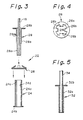
- the fixing device 22 comprises a sleeve member 24 inserted to the through hole formed in the panel 16, a push-on or quick nut 26 for engaging with and fastening the inserted sleeve member 24 to the panel 16, and a ferrule member 28 held by the sleeve member 26 and having the optical fiber 18 fixed therein.
- the sleeve member 24 may be made of a suitable metal material or a suitable hard synthetic resin material, and includes a sleeve body 24a having an outer diameter that is slightly smaller than an inner diameter of the through hole formed in the panel 16, and a flange 24b integrally formed at one end of the sleeve body 24a. As best shown in Fig.
- the sleeve body 24a has a small opening 24c formed at the other end side thereof, and a ridge element 24d integrally formed on the inner wall surface thereof and at one side of the othe end thereof.
- the ridge element 24d may be formed by pressing.
- the sleeve member 24 is inserted to the through hole of the panel 16 from the outer display surface side thereof, until the flange 24b is abutted thereagainst, as shown in Fig. 2.
- the insertion of the sleeve member 24 may be carried out by pulling up same with a suitable tool engaged with the small opening 24c, if necessary.
- the quick nut 26 is engaged with a portion of the sleeve body 24a projected from an inner surface of the panel 16.
- the quick nut 26 is preferably made of a steel material, and comprises an annular ring plate 26a and four pawl elements 26 integrally and inwardly extended therefrom, as apparent from Figs. 3 and 4.
- the diameter of a circle defined by inner edges of the pawl elements 26 is slightly smaller than that of the sleeve body 24a.
- the ferrule member 28 is made of a plastically deformable material such as a suitable metal or a suitable synthetic resin, and includes a tubular body 28a for receiving the optical fiber 18 therein, and a flange 28b integrally formed at one end thereof. As best shown in Fig. 3, the tubular body 28a has a reduced thin portion 28a1 and an enlarged thick portion 28a2 integrated therewith. The reduced thin portion 28a1 is swaged by a suitable tool after the optical fiber 18 is received in the ferrule 28, so that the received optical fiber 18 is immovably fixed within the tubular body 28a. Note, after the optical fiber 18 is fixed in the ferrule member 28, the end face of the optical fiber 18 is treated, if necessary.
- An outer diameter of the enlarged thick portion 28a2 is slightly smaller than the inner diameter of the sleeve body 24a, so that the ferrule member 28 can be inserted into the sleeve member 24 until the flange 28b of the ferrule member 28 is abutted against the end of the sleeve member 24, as shown in Fig. 2. Nevertheless, the ferrule member 28 must be forcibly inserted in the sleeve member 24 to enable it to pass over the ridge element 24d integrally formed on the inner wall surface thereof, i.e., the inserted ferrule member 28 is firmly held within the sleeve member 24 by the engagement of the ferrule member 28 with the ridge element 24d.
- the ferrule member 28 held by the sleeve member 24 can withstand a pulling force of at least from 3 to 5 kg, and thus the ferrule member 28 is not easily removed from the sleeve member 24.
- projections may be formed on the inner wall surface of the sleeve member 24, so that the ferrule member 28 can withstand a pulling force of more than 5 kg.
- the ridge element 24d is provided on the inner wall surface of the sleeve member 24, it may be formed on the outer surface of the ferrule member 28.
- the implanting of the optical fibers 18 in the panel 18 is easier and quicker in comparison with the conventional implanting of optical fibers in which an adhesive is used for fixing same, and thus the optical fiber display apparatus as shown in Fig. 1 can be advantageously assembled by use of the fixing device 22, especially on site.
- a protective transparent board 30, which may be made of a glass or acrylic resin, is attached to the display surface of the panel 16, to protect the exposed end faces of the optical fibers 18 from pollution or contamination whenever necessary.
- Figure 5 shows another type of ferrule member, generally indicated by a reference numeral 32, which includes a thin tubular body 32a and a flange 32b integrally formed at one end thereof.
- the tubular body 32a has substantially the same diameter as the enlarged thick portion 28a2 of the ferrule member 28, but an inner diameter thereof is larger than that of the ferrule member 28 for receiving an optical fiber 34 having a larger diameter than that of the optical fiber 18.
- the single sleeve member 24 can be commonly used for the two ferrule members 28 and 32 in which the optical fibers 18 and 34 having different diameters are received.
- the tubular body 32a must be partially swaged before the optical fiber 34 can be fixed in the ferrule member 32. It is preferable to prepare various type ferrules having the same diameter and different inner diameters (for example, from 0.25 to 3.0 mm).
- FIG. 6 shows an optical fiber display apparatus constituted as a decorative illumination such as a chandelier.
- This display apparatus comprises a box-like casing 36 which may be constituted in substantially the same manner as the casing 10.
- a bottom wall 38 of the casing 36 serves as a display panel in which a plurality of through holes are formed.
- the display apparatus also comprises a first plurality of optical fibers 40 which are divided into two groups C and D.
- the optical fibers of group C are gathered together at one end thereof and are optically connected to a light source 42C attached to an inner wall portion of the side wall frame of the casing 36.
- the optical fibers of group D are gathered together at one end thereof and are optically connected to a light source 42D attached to an opposed inner wall portion of the side wall frame of the casing 36.
- the other ends of each of the optical fibers 40 of the groups C and D are implanted in the panel 38.
- the display apparatus further comprises a second plurality of optical fibers 44, one end of each is implanted in the panel 38 to be thus suspended therefrom, and is optically connected to the corresponding one end of the implanted optical fibers 40.
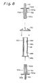
- the implanting and connecting of the optical fibers 40, 44 is carried out by using a fixing device 46 as shown in Figs. 7 and 8.
- the fixing device 46 comprises a sleeve member 48 inserted to the through hole formed in the panel 38, a push-on or quick nut 50 for engaging with and fastening the inserted sleeve member 48 to the panel 38. a first ferrule member 52 held by the sleeve member 48 and having the optical fiber 40 fixed therein, and a second ferrule member 54 held by the sleeve member 48 and having the optical fiber 44 fixed therein.
- the sleeve member 48 may be made of a suitable metal material or a suitable hard synthetic resin material, and includes a sleeve body 48a having an outer diameter sligthly than an inner diameter of the through hole formed in the panel 38, and a flange 48b integrally formed at one end of the sleeve body 48a. As best shown in Fig. 8, the sleeve body 48a has a small opening 48c formed at the side of the other end thereof, and first and second ridge elements 48d and 48e integrally formed on the inner wall surface thereof and at the sides of the ends thereof, respectively. When the sleeve member 48 is made of a metal material, the ridge elements 48d and 48e may be formed by pressing.
- the sleeve member 48 is inserted to the through hole of the panel 38 from the outer display surface side thereof until the flange 48b is abutted thereagainst, as shown in Fig. 7.
- the sleeve member 48 may be inserted by pulling up same with a suitable tool engaged with the small opening 48c, if necessary.
- the quick nut 50 is engaged with a portion of the sleeve body 48a projected from an inner surface of the panel 38.
- the quick nut 50 is substantially identical to the quick nut 26 shown in Figs. 2, 3 and 4.
- the four pawl elements of the quick nut 50 are firmly engaged with the outer surface of the sleeve body 48a, whereby the sleeve member 48 is prevented from dropping out of the through hole of the panel 38.
- the first and second ferrule members 52 and 54 are substantially identical to the ferrule member 28 shown in Figs. 2 and 3. Namely, each of the ferrule members 52 and 54 is made of a plastically deformable material such as a suitable metal or a suitable synthetic resin, and includes a tubular body 52a, 54a for receiving the optical fiber 40, 44 therein and a flange 52b, 54b integrally formed at one end thereof. Also, each of the tubular bodies 52a and 54a has a reduced thin portion 52a1 , 52a1 and an enlarged thick portion 52a2, 52a2 integrated therewith, as best shown in Fig. 8.
- a plastically deformable material such as a suitable metal or a suitable synthetic resin
- the reduced thin portion 52a1, 54a1 is swaged by a suitable tool after the optical fiber 40, 44 is received in the ferrule 52, 54, so that the received optical fiber 40, 44 is immovably fixed within the tubular body 52a, 52a. Note, after the optical fiber 40, 44 is fixed in the ferrule member 52, 54, the end face of the optical fiber 40, 44 is treated, if necessary.
- the outer diameter of enlarged thick portion 52a2, 54a2 is slightly smaller than the inner diameter of the sleeve body 48a, so that the ferrule members 52 and 54 can be inserted to the sleeve member 24 from the opposed end sides thereof, until the flanges 52b and 52b are abutted against the opposed ends of the sleeve member 48 as shown in Fig. 7.
- ferrule members 52 and 54 must be forcibly inserted in the sleeve member 48 because of the ridge elements 48d and 48e integrally formed on the inner wall surface thereof, whereby the inserted ferrule members 52 and 54 are firmly held in the sleeve member 48 by the engagement of the ferrule members 52 and 54 with the ridge element 48d and 48e, respectively.
- the optical fibers 40 and 44 can be easily and quickly implanted in the panel 38 and thus the optical fiber display apparatus as shown in Fig. 6 can be advantageously assembled by use of the fixing device 22, especially on site.
- the optical fibers 44 suspended from the display panel 38 are constituted such that light can partially leak out of discrete locations on the surface of the optical fibers 44, whereby a decorative effect thereof can be increased.
- FIG 9 shows a decorative optical fiber which can be advantageously used as the optical fiber 44.
- This decorative optical fiber generally indicated by a reference numeral 56, comprises a core 58 and a cladding 60 surrounding same, and is characterized in that a plurality of cone-shaped openings 62 are discretely formed over the surface thereof. A light conducted in the core 58 is allowed to partially leak out of the openings 62, and thus a decorative effect of the optical fiber 56 is increased.
- the decorative optical fiber 56 is not susceptible to breaking, due to the cone shape of the openings 62.
- the decorative optical fiber 56 is made of suitable synthetic resin materials to enable an easy formation of the cone-shaped openings 62. Namely, the cone-shaped opening 62 can be easily formed by a penetraton of a heated needle element into the core 58, through the cladding 60.
- the cone-shaped openings 62 may be filled with a suitable transparent adhesive material 62, such as an ultraviolet-curing type adhesive, visible light-curing type adhesive, one-component type adhesive, two-component type adhesive or the like, as shown in Fig. 10, so that the decorative optical fibers 56 are strengthened against breakage.
- the adhesive material 64 is made proud at the surface of the cladding 60, as shown in Fig. 10, so that the leaked light is scattered at the raised portion of the adhesive material 64, whereby the decorative effect is further increased.
- the raised portion of the adhesive material 64 has a semi-spherical shape, it may have any other shape.
- the adhesive material 64 may be colored by mixing a suitable dye therewith.
- lens elements may be inserted to the openings 60 and adhered thereto.
- the openings 62 are diametrically disposed over the surface of the optical fiber 56, they may be disposed along the surface of the optical fiber 56 at one side thereof, as shown in Fig. 11. Note, the arrangement of the cone-shaped openings 62 can be carried out in various ways. For example, the openings 62 may be helically or circularly disposed on the surface of the optical fiber 56.
Landscapes
- Physics & Mathematics (AREA)
- General Physics & Mathematics (AREA)
- Engineering & Computer Science (AREA)
- Theoretical Computer Science (AREA)
- Optics & Photonics (AREA)
- Mechanical Coupling Of Light Guides (AREA)
- Optical Fibers, Optical Fiber Cores, And Optical Fiber Bundles (AREA)
- Optical Couplings Of Light Guides (AREA)
Applications Claiming Priority (2)
| Application Number | Priority Date | Filing Date | Title |
|---|---|---|---|
| JP46436/90U | 1990-04-27 | ||
| JP1990046436U JPH0749442Y2 (ja) | 1990-04-27 | 1990-04-27 | 光ファイバコネクタ |
Publications (3)
| Publication Number | Publication Date |
|---|---|
| EP0459153A2 true EP0459153A2 (fr) | 1991-12-04 |
| EP0459153A3 EP0459153A3 (en) | 1992-12-02 |
| EP0459153B1 EP0459153B1 (fr) | 1998-07-01 |
Family
ID=12747110
Family Applications (1)
| Application Number | Title | Priority Date | Filing Date |
|---|---|---|---|
| EP91106791A Expired - Lifetime EP0459153B1 (fr) | 1990-04-27 | 1991-04-26 | Dispositif d'affichage à fibres optiques |
Country Status (4)
| Country | Link |
|---|---|
| US (1) | US5129032A (fr) |
| EP (1) | EP0459153B1 (fr) |
| JP (1) | JPH0749442Y2 (fr) |
| DE (1) | DE69129679T2 (fr) |
Cited By (4)
| Publication number | Priority date | Publication date | Assignee | Title |
|---|---|---|---|---|
| EP0749104A1 (fr) * | 1995-06-13 | 1996-12-18 | ABBPATENT GmbH | Dispositif pour transmettre vers l'extérieur la lumière émise par une source située à l'intérieur d'un boîtier |
| WO2003021555A3 (fr) * | 2001-08-15 | 2004-07-22 | Optica Fibre Technologies Msc | Trajet optique utilise dans un systeme d'affichage a fibres optiques |
| FR2989177A1 (fr) * | 2012-04-06 | 2013-10-11 | Airbus Corporate Jet Ct | Dispositif de support d'une fibre optique dans un revetement textile et procede d'installation associe |
| DE10160296B4 (de) * | 2001-12-07 | 2014-09-11 | Robert Bosch Gmbh | Anzeigevorrichtung |
Families Citing this family (9)
| Publication number | Priority date | Publication date | Assignee | Title |
|---|---|---|---|---|
| US5532711A (en) * | 1991-09-27 | 1996-07-02 | Inwave Corporation | Lightweight display systems and methods for making and employing same |
| US5818998A (en) * | 1994-03-25 | 1998-10-06 | Inwave Corporation | Components for fiber-optic matrix display systems |
| US5740296A (en) * | 1996-09-05 | 1998-04-14 | Inwave Corporation | Adjustable terminal housing for optical fiber |
| US6195016B1 (en) | 1999-08-27 | 2001-02-27 | Advance Display Technologies, Inc. | Fiber optic display system with enhanced light efficiency |
| US6547448B2 (en) * | 2001-05-15 | 2003-04-15 | The Boeing Company | Embeddable fiber optic connector and associated method |
| US6913454B2 (en) * | 2003-07-08 | 2005-07-05 | Skh Technologies Llc | Apparatus and method for attaching filamentary members to a substrate |
| US7020362B2 (en) * | 2003-08-05 | 2006-03-28 | Jonathan Simon | Low cost optical interconnect for fiber optic system |
| JP5344095B2 (ja) * | 2010-10-08 | 2013-11-20 | 株式会社オートネットワーク技術研究所 | 光コネクタ用スリーブおよび光コネクタ |
| US9423547B1 (en) | 2013-06-11 | 2016-08-23 | Independent Paradigm, Llc | Optical fiber light apparatus, and balloon apparatus provided with such optical fiber light apparatus |
Family Cites Families (21)
| Publication number | Priority date | Publication date | Assignee | Title |
|---|---|---|---|---|
| DE2542590A1 (de) * | 1975-09-24 | 1977-04-07 | Siemens Ag | Anzeigevorrichtung |
| CA1093873A (fr) * | 1978-06-05 | 1981-01-20 | Helmut H. Lukas | Traduction non-disponible |
| JPS5669705A (en) * | 1979-11-07 | 1981-06-11 | Ikeda Denki Kk | Illuminator |
| DE2944862A1 (de) * | 1979-11-07 | 1981-05-21 | Philips Patentverwaltung Gmbh, 2000 Hamburg | Vorrichtung zum befestigen eines elektrischen geraetes an einem durchbruch eines kraftfahrzeugteiles |
| US4815815A (en) * | 1979-11-13 | 1989-03-28 | Kei Mori | Device and a method of directing light energy to a predetermined area in the sea |
| GB2114353A (en) * | 1981-11-06 | 1983-08-17 | Eurotec Fibre Optics Ltd | Variable illuminated display sign |
| FR2516285A1 (fr) * | 1981-11-10 | 1983-05-13 | Dupuis Robert | Serpentin lumineux et son procede de fabrication |
| IT1152421B (it) * | 1982-06-18 | 1986-12-31 | Giulio Properzi | Gruppo di laminazione per un laminatoio per barre metalliche e simili |
| JPS6049501A (ja) * | 1983-08-30 | 1985-03-18 | 日本電気株式会社 | 磁器組成物 |
| JPS6078004A (ja) * | 1983-10-03 | 1985-05-02 | 大林道路株式会社 | アイスバ−ン舗装体の施工方法 |
| JPS60125601A (ja) * | 1983-12-12 | 1985-07-04 | リョービ株式会社 | 電動チエンソ− |
| JPS6160404A (ja) * | 1984-08-29 | 1986-03-28 | ナショナル住宅産業株式会社 | シ−ト梱包装置 |
| GB8423357D0 (en) * | 1984-09-15 | 1984-11-07 | Motorola Israel Ltd | Flat light source |
| DE3434805A1 (de) * | 1984-09-19 | 1986-03-27 | Siemens AG, 1000 Berlin und 8000 München | Abtasteinrichtung zur beleuchtung und optischen abtastung einer flaechenhaften vorlage |
| IL80008A0 (en) * | 1986-09-11 | 1986-12-31 | Ispra Israel Prod Res Co Ltd | Plate of laminated glass |
| JPS63182004A (ja) * | 1987-01-22 | 1988-07-27 | Showa Denko Kk | 水溶液の濃縮装置 |
| US4814948A (en) * | 1987-07-02 | 1989-03-21 | Yasuo Hasegawa | Light-emitting-end mounting mechanism in optical display panel |
| DE3735037A1 (de) * | 1987-10-16 | 1989-04-27 | Philips Patentverwaltung | Steckerstift fuer einen lichtwellenleiter |
| US4917448A (en) * | 1988-10-27 | 1990-04-17 | Oppenheimer M David | Lighted display device |
| DE68927640D1 (de) * | 1989-09-13 | 1997-02-20 | Tradebest Int Corp | Autonome, visuell anziehende Vorrichtung mit einem über den Kanten beleuchteten Paneel |
| US5013109A (en) * | 1989-11-06 | 1991-05-07 | Fiber Tech, Inc. | Modular system for decorative lighting |
-
1990
- 1990-04-27 JP JP1990046436U patent/JPH0749442Y2/ja not_active Expired - Fee Related
-
1991
- 1991-04-26 EP EP91106791A patent/EP0459153B1/fr not_active Expired - Lifetime
- 1991-04-26 US US07/691,834 patent/US5129032A/en not_active Expired - Lifetime
- 1991-04-26 DE DE69129679T patent/DE69129679T2/de not_active Expired - Fee Related
Cited By (5)
| Publication number | Priority date | Publication date | Assignee | Title |
|---|---|---|---|---|
| EP0749104A1 (fr) * | 1995-06-13 | 1996-12-18 | ABBPATENT GmbH | Dispositif pour transmettre vers l'extérieur la lumière émise par une source située à l'intérieur d'un boîtier |
| WO2003021555A3 (fr) * | 2001-08-15 | 2004-07-22 | Optica Fibre Technologies Msc | Trajet optique utilise dans un systeme d'affichage a fibres optiques |
| DE10160296B4 (de) * | 2001-12-07 | 2014-09-11 | Robert Bosch Gmbh | Anzeigevorrichtung |
| FR2989177A1 (fr) * | 2012-04-06 | 2013-10-11 | Airbus Corporate Jet Ct | Dispositif de support d'une fibre optique dans un revetement textile et procede d'installation associe |
| US9388974B2 (en) | 2012-04-06 | 2016-07-12 | Airbus Corporate Jet Centre | Textile covering incorporating an optical fibre and associated installation method |
Also Published As
| Publication number | Publication date |
|---|---|
| JPH0749442Y2 (ja) | 1995-11-13 |
| US5129032A (en) | 1992-07-07 |
| DE69129679D1 (de) | 1998-08-06 |
| DE69129679T2 (de) | 1999-02-04 |
| EP0459153A3 (en) | 1992-12-02 |
| JPH046006U (fr) | 1992-01-21 |
| EP0459153B1 (fr) | 1998-07-01 |
Similar Documents
| Publication | Publication Date | Title |
|---|---|---|
| US5129032A (en) | Optical fiber display apparatus, fixing device for optical fiber used therein, and decorative optical fiber usable therein | |
| CN102812324B (zh) | 照准装置 | |
| TW440716B (en) | Fiber optic luminaire | |
| US5018821A (en) | Optical connector ferrule and method for assembling the same | |
| CA2059722C (fr) | Panneau eclairant a fibres optiques | |
| US5398170A (en) | Optical-fiber display with intensive brightness | |
| CA2042144A1 (fr) | Moyen de raccordement entre une source de lumiere et un faisceau de fibres optiques et moyen de fabrication connexe | |
| IL109432A0 (en) | Imaging ball lens optically immersed with a fiber optic faceplate | |
| US7186012B2 (en) | Lighting element with a light emitting diode | |
| IT8921866A0 (it) | Procedimento per la realizzazione di gruppo di connessione separabile per fibre ottiche riunite a nastro e gruppo di connessione con esso realizzato. | |
| US6735367B2 (en) | Illumination light conducting optical-fiber configuration for endoscope cable | |
| CA2159136A1 (fr) | Ensemble del a fibres optiques | |
| KR960011463A (ko) | 광섬유 커넥터 | |
| EP0031146A3 (en) | Coupling device between an optical fibre and a light source and method of assembling the same | |
| EP0069870A1 (fr) | Ligne de transmission d'une image | |
| KR890003266B1 (ko) | 패널 표시기 | |
| EP0066218A1 (fr) | Dispositif pour la transmission contrôlée de lumière d'une fibre optique à une autre | |
| KR102663593B1 (ko) | 케이블선로 인디케이터 | |
| JPS63155007A (ja) | 照明装置 | |
| JP6598276B1 (ja) | 液位の測定具 | |
| WO1998037536A1 (fr) | Panneau a fibres optiques a changement de couleurs | |
| US20030219200A1 (en) | Light coupling apparatus and method | |
| KR100394170B1 (ko) | 광 케이블을 이용한 조명장치 | |
| JP3329739B2 (ja) | プラネタリウムにおける投映光学系 | |
| KR200255895Y1 (ko) | 광 케이블을 이용한 조명장치 |
Legal Events
| Date | Code | Title | Description |
|---|---|---|---|
| PUAI | Public reference made under article 153(3) epc to a published international application that has entered the european phase |
Free format text: ORIGINAL CODE: 0009012 |
|
| 17P | Request for examination filed |
Effective date: 19910426 |
|
| AK | Designated contracting states |
Kind code of ref document: A2 Designated state(s): DE |
|
| PUAL | Search report despatched |
Free format text: ORIGINAL CODE: 0009013 |
|
| AK | Designated contracting states |
Kind code of ref document: A3 Designated state(s): DE |
|
| 17Q | First examination report despatched |
Effective date: 19941104 |
|
| GRAG | Despatch of communication of intention to grant |
Free format text: ORIGINAL CODE: EPIDOS AGRA |
|
| GRAG | Despatch of communication of intention to grant |
Free format text: ORIGINAL CODE: EPIDOS AGRA |
|
| GRAH | Despatch of communication of intention to grant a patent |
Free format text: ORIGINAL CODE: EPIDOS IGRA |
|
| GRAG | Despatch of communication of intention to grant |
Free format text: ORIGINAL CODE: EPIDOS AGRA |
|
| GRAH | Despatch of communication of intention to grant a patent |
Free format text: ORIGINAL CODE: EPIDOS IGRA |
|
| GRAH | Despatch of communication of intention to grant a patent |
Free format text: ORIGINAL CODE: EPIDOS IGRA |
|
| GRAA | (expected) grant |
Free format text: ORIGINAL CODE: 0009210 |
|
| AK | Designated contracting states |
Kind code of ref document: B1 Designated state(s): DE |
|
| REF | Corresponds to: |
Ref document number: 69129679 Country of ref document: DE Date of ref document: 19980806 |
|
| PLBE | No opposition filed within time limit |
Free format text: ORIGINAL CODE: 0009261 |
|
| STAA | Information on the status of an ep patent application or granted ep patent |
Free format text: STATUS: NO OPPOSITION FILED WITHIN TIME LIMIT |
|
| 26N | No opposition filed | ||
| PGFP | Annual fee paid to national office [announced via postgrant information from national office to epo] |
Ref country code: DE Payment date: 20030508 Year of fee payment: 13 |
|
| PG25 | Lapsed in a contracting state [announced via postgrant information from national office to epo] |
Ref country code: DE Free format text: LAPSE BECAUSE OF NON-PAYMENT OF DUE FEES Effective date: 20041103 |