EP0459725A1 - Appareil d'enregistrement sur disques magnétiques - Google Patents
Appareil d'enregistrement sur disques magnétiques Download PDFInfo
- Publication number
- EP0459725A1 EP0459725A1 EP91304742A EP91304742A EP0459725A1 EP 0459725 A1 EP0459725 A1 EP 0459725A1 EP 91304742 A EP91304742 A EP 91304742A EP 91304742 A EP91304742 A EP 91304742A EP 0459725 A1 EP0459725 A1 EP 0459725A1
- Authority
- EP
- European Patent Office
- Prior art keywords
- magnetic
- magnetic disk
- head
- disk apparatus
- disk
- Prior art date
- Legal status (The legal status is an assumption and is not a legal conclusion. Google has not performed a legal analysis and makes no representation as to the accuracy of the status listed.)
- Granted
Links
- 239000000758 substrate Substances 0.000 claims abstract description 24
- 239000011521 glass Substances 0.000 claims abstract description 11
- 239000000919 ceramic Substances 0.000 claims abstract description 5
- 239000002131 composite material Substances 0.000 claims description 2
- 239000012811 non-conductive material Substances 0.000 claims description 2
- 239000010409 thin film Substances 0.000 claims description 2
- 239000000463 material Substances 0.000 claims 2
- 230000008878 coupling Effects 0.000 abstract description 3
- 238000010168 coupling process Methods 0.000 abstract description 3
- 238000005859 coupling reaction Methods 0.000 abstract description 3
- 230000006866 deterioration Effects 0.000 abstract description 2
- XAGFODPZIPBFFR-UHFFFAOYSA-N aluminium Chemical compound [Al] XAGFODPZIPBFFR-UHFFFAOYSA-N 0.000 description 7
- 229910052782 aluminium Inorganic materials 0.000 description 7
- 238000005259 measurement Methods 0.000 description 5
- 230000000694 effects Effects 0.000 description 2
- 238000007796 conventional method Methods 0.000 description 1
- 238000002474 experimental method Methods 0.000 description 1
- 230000003993 interaction Effects 0.000 description 1
Images
Classifications
-
- G—PHYSICS
- G11—INFORMATION STORAGE
- G11B—INFORMATION STORAGE BASED ON RELATIVE MOVEMENT BETWEEN RECORD CARRIER AND TRANSDUCER
- G11B5/00—Recording by magnetisation or demagnetisation of a record carrier; Reproducing by magnetic means; Record carriers therefor
- G11B5/48—Disposition or mounting of heads or head supports relative to record carriers ; arrangements of heads, e.g. for scanning the record carrier to increase the relative speed
- G11B5/488—Disposition of heads
- G11B5/4886—Disposition of heads relative to rotating disc
-
- G—PHYSICS
- G11—INFORMATION STORAGE
- G11B—INFORMATION STORAGE BASED ON RELATIVE MOVEMENT BETWEEN RECORD CARRIER AND TRANSDUCER
- G11B5/00—Recording by magnetisation or demagnetisation of a record carrier; Reproducing by magnetic means; Record carriers therefor
- G11B5/012—Recording on, or reproducing or erasing from, magnetic disks
-
- G—PHYSICS
- G11—INFORMATION STORAGE
- G11B—INFORMATION STORAGE BASED ON RELATIVE MOVEMENT BETWEEN RECORD CARRIER AND TRANSDUCER
- G11B5/00—Recording by magnetisation or demagnetisation of a record carrier; Reproducing by magnetic means; Record carriers therefor
- G11B5/62—Record carriers characterised by the selection of the material
- G11B5/68—Record carriers characterised by the selection of the material comprising one or more layers of magnetisable material homogeneously mixed with a bonding agent
- G11B5/70—Record carriers characterised by the selection of the material comprising one or more layers of magnetisable material homogeneously mixed with a bonding agent on a base layer
- G11B5/716—Record carriers characterised by the selection of the material comprising one or more layers of magnetisable material homogeneously mixed with a bonding agent on a base layer characterised by two or more magnetic layers
- G11B5/718—Record carriers characterised by the selection of the material comprising one or more layers of magnetisable material homogeneously mixed with a bonding agent on a base layer characterised by two or more magnetic layers at least one on each side of the base layer
-
- G—PHYSICS
- G11—INFORMATION STORAGE
- G11B—INFORMATION STORAGE BASED ON RELATIVE MOVEMENT BETWEEN RECORD CARRIER AND TRANSDUCER
- G11B5/00—Recording by magnetisation or demagnetisation of a record carrier; Reproducing by magnetic means; Record carriers therefor
- G11B5/62—Record carriers characterised by the selection of the material
- G11B5/73—Base layers, i.e. all non-magnetic layers lying under a lowermost magnetic recording layer, e.g. including any non-magnetic layer in between a first magnetic recording layer and either an underlying substrate or a soft magnetic underlayer
- G11B5/739—Magnetic recording media substrates
- G11B5/73911—Inorganic substrates
- G11B5/73921—Glass or ceramic substrates
Definitions
- the invention relates to a magnetic disk apparatus including recording disks with glass or ceramic as the disk substrate.
- magnetic disk drives employing hard disks have commonly used aluminum as the disk substrate.
- glass and ceramic substrates have been considered.
- Such disk substrates have excellent surface characteristics which permit a reduction in magnetic head flying height thereby making possible an increase in recording density.
- the conventional aluminum disk substrate can shield the electromagnetic coupling of a pair of upper and lower magnetic heads located on opposite sides of the disk.
- a glass or ceramic substrate does not provide such a shielding function.
- This electromagnetic coupling causes an increase in crosstalk noise and a deterioration in the quality of the reproduced signal.
- measurements of the crosstalk (at the 4 MHz output level) for the glass substrate disk and the aluminum substrate disk, both 1.27 mm thick show that the crosstalk of the glass substrate disk is +8.9 dB higher than that of the aluminum substrate disk.
- the attenuation ratio of the reproduced signal is defined as f′ 4M / f 4M
- the ratio of crosstalk as f′ 1.5M / f′ 4M , and f 4M , f′ 4M , and f′ 1.5M for glass substrate disk are measured, the ratios are -1.73 dB and -46.4 dB, respectively.
- measurements of f 4M , f′ 4M , and f′ 1.5M for the aluminum substrate disk reveal that the attenuation ratio of the reproduced signal and the ratio of crosstalk are -0.38 dB and -60.6 dB, respectively.
- H c 1 x 10³ Oe
- Mt 4.2 x 10 ⁇ 3 emu/cm2 for the aluminum substrate disk
- H c 1.25 x 10³ Oe
- Mt 4.0 x 10 ⁇ 3 emu/cm2 for the glass substrate disk
- the magnetic head used in the measurements had a gap length of 0.6 ⁇ m, and the width of a data track, T w , was equal to 10 ⁇ m. In addition, the flying height of the magnetic head was 8 ⁇ .
- the invention seeks to reduce the above mentioned electromagnetic crosstalk and attenuation and accordingly provides a magnetic disk apparatus including at least one magnetic disk comprising a substrate composed of an electrically non-conductive material and a magnetic recording layer on both surfaces of the substrate, the apparatus comprising: a first magnetic head located adjacent to a first surface of the magnetic disk; and a second magnetic head located adjacent to a second surface of the magnetic disk; wherein the first and second magnetic heads are shifted with respect to one another.
- top and bottom heads may be circumferentially shifted with respect to one another, i.e. shifted in the direction of motion of the rotating disk, it is preferred that the heads are shifted radially with respect to one another.
- the magnetic disk apparatus 12 includes a base 6 and an upper cover 7. On the base 6, an actuator 8 is mounted by a shaft 12, and to the actuator 8, sliders 3a, 3b are mounted across the magnetic disk and on the top and bottom surfaces. On the opposite side of the actuator 8 and shaft 12, a coil 9 is fixed. Above the coil 9, at a fixed distance, an upper yoke 10a is mounted on the base. Below the coil, at a fixed distance, a lower yoke 10b is also mounted on the base 6. On the upper yoke 10a and a lower yoke 10b, permanent magnets 11a, 11b are mounted on the side of coil. The coil and permanent magnets form the voice coil motor, and the interaction of the magnetic field of the permanent magnets with the current flowing through the coil causes movement of the actuator. The extent of movement of the actuator is determined by the amount of current flowing through coil.
- the substrate of magnetic disk 1 is glass, and a magnetic layer (not shown) is deposited on the top and bottom surfaces of the substrate.
- a first magnetic head 2a is arranged on the top side of the magnetic disk 1 and is supported by a first slider 3a relative to the surface of the disk during disk rotation.
- current is provided from the drive circuit (not shown in Fig. 1) to the coil of the first magnetic head 2a.
- a second head 2b is arranged on the bottom surface of the magnetic disk 1 and is supported by a second slider 3b relative to the disk surface during rotation of the disk. Data recorded on the bottom surface of the magnetic disk 1 in the same way as the top surface except that current is provided by the aforementioned drive circuit to the coil of the second magnetic head 2b.
- Both magnetic heads are monolithic heads, incorporated into the sliders.
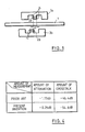
- the first magnetic head 2a and the second magnetic head 2b are shifted with respect to one another in a radial direction by a distance d, where d corresponds to an integral number of recording track widths.
- a series of measurements is taken as follows to obtain the aforementioned attenuation and crosstalk ratios. Firstly the 4 MHz signal is recorded onto the top surface of the magnetic disk by the first magnetic head. The 4 MHz signal is then reproduced by the first head to give f′ 4M . In the next step the 1.5 MHz signal is recorded by the second head onto the bottom surface of the magnetic disk. The 4 MHz signal is then reproduced again by the top head to give f′ 4M . The 1.5 MHz signal is reproduced at the same time by the top head to give f′ 1.5M . As described previously, the crosstalk ratio is defined as f′ 1.5M /f′ 4M and the attenuation ratio by f′ 4M /f 4M .
- the attenuation and the crosstalk of the reproduced signals are reduced sharply, from -1.73 dB to -0.29 dB, and from -46.4 dB to -54.6 dB, respectively.
- the thickness of the magnetic disk, the magnetic characteristic of recording layer of magnetic disk, and the characteristics of magnetic head, are similar to as mentioned before.
- shifting the position of the magnetic gap in the direction of rotation of magnetic disk can also reduce the attenuation and the crosstalk of the reproduced signal as mentioned above.
- the most effective way to reduce the attenuation and the crosstalk is by shifting the recording track of the first and the second magnetic heads.
- the magnetic head is a monolithic head but it will apparent that the similar effects will be found with a thin film head or a composite head.
- reducing the thickness of the substrate, reducing the coercive force (H c ) of the magnetic media, and lowering the flying height of the magnetic head can also increase the effect of the invention.
Landscapes
- Chemical & Material Sciences (AREA)
- Engineering & Computer Science (AREA)
- Ceramic Engineering (AREA)
- Inorganic Chemistry (AREA)
- Recording Or Reproducing By Magnetic Means (AREA)
- Adjustment Of The Magnetic Head Position Track Following On Tapes (AREA)
- Magnetic Heads (AREA)
- Magnetic Record Carriers (AREA)
Applications Claiming Priority (2)
| Application Number | Priority Date | Filing Date | Title |
|---|---|---|---|
| JP135506/90 | 1990-05-28 | ||
| JP2135506A JP2935129B2 (ja) | 1990-05-28 | 1990-05-28 | 固定磁気ディスク装置及び関連する装置・方法 |
Publications (2)
| Publication Number | Publication Date |
|---|---|
| EP0459725A1 true EP0459725A1 (fr) | 1991-12-04 |
| EP0459725B1 EP0459725B1 (fr) | 1998-02-04 |
Family
ID=15153354
Family Applications (1)
| Application Number | Title | Priority Date | Filing Date |
|---|---|---|---|
| EP91304742A Expired - Lifetime EP0459725B1 (fr) | 1990-05-28 | 1991-05-24 | Appareil d'enregistrement sur disques magnétiques |
Country Status (13)
| Country | Link |
|---|---|
| US (1) | US5296980A (fr) |
| EP (1) | EP0459725B1 (fr) |
| JP (1) | JP2935129B2 (fr) |
| KR (1) | KR0141090B1 (fr) |
| CN (1) | CN1021383C (fr) |
| AU (1) | AU639559B2 (fr) |
| BR (1) | BR9102008A (fr) |
| CA (1) | CA2042871A1 (fr) |
| CZ (1) | CZ283110B6 (fr) |
| DE (1) | DE69128848T2 (fr) |
| HU (1) | HU212523B (fr) |
| PL (1) | PL166646B1 (fr) |
| RU (1) | RU2072564C1 (fr) |
Families Citing this family (4)
| Publication number | Priority date | Publication date | Assignee | Title |
|---|---|---|---|---|
| JP3326549B2 (ja) * | 1996-10-18 | 2002-09-24 | ミネベア株式会社 | 磁気ヘッド装置 |
| US7206154B2 (en) * | 2002-09-25 | 2007-04-17 | Hitachi Global Storage Technologies Netherlands, B.V. | Method and apparatus for balanced shield shunts, leads and pads for electrical noise reduction in read heads |
| RU172200U1 (ru) * | 2016-12-26 | 2017-06-30 | Андрей Викторович Мельников | Приспособление для замены блока магнитных головок жесткого диска |
| US10991387B1 (en) * | 2020-03-27 | 2021-04-27 | Western Digital Technologies, Inc. | Data storage device migrating data from non-energy assist disk surface to energy assist disk surface |
Citations (5)
| Publication number | Priority date | Publication date | Assignee | Title |
|---|---|---|---|---|
| US4738885A (en) * | 1986-02-24 | 1988-04-19 | Kyocera Corporation | Magnetic disk, substrate therefor and process for preparation thereof |
| US4803106A (en) * | 1986-07-16 | 1989-02-07 | Siemens Aktiengesellschaft | Disc-shaped carrier body for a recording medium and method for manufacturing same |
| US4907112A (en) * | 1987-03-09 | 1990-03-06 | Matsushita Electric Industrial Co., Ltd. | Recording/reproducing head providing evenly distributed contact pressure with magnetic medium |
| US4912582A (en) * | 1983-10-25 | 1990-03-27 | Seiko Epson Kabushiki Kaisha | Floppy disk drive system with improved record/playback heads |
| US4953046A (en) * | 1985-04-27 | 1990-08-28 | Juki Corporation | Device for supporting magnetic heads for double sided discs |
Family Cites Families (9)
| Publication number | Priority date | Publication date | Assignee | Title |
|---|---|---|---|---|
| US3789156A (en) * | 1972-03-27 | 1974-01-29 | Rca Corp | High density isolated multi-channel magnetic circuit transducer |
| JPS59185708U (ja) * | 1983-05-21 | 1984-12-10 | 株式会社三協精機製作所 | 磁気デイスクの両面記録再生用磁気ヘツド装置 |
| JPH0351778Y2 (fr) * | 1984-08-31 | 1991-11-07 | ||
| AU576947B2 (en) * | 1985-03-08 | 1988-09-08 | Sony Corporation | Combination magnetic transducer head |
| JPS61255559A (ja) * | 1985-05-09 | 1986-11-13 | Hitachi Maxell Ltd | 磁気ヘツドキヤリツジアセンブリ |
| US4807054A (en) * | 1985-08-14 | 1989-02-21 | Miniscribe Corporation | Transducer support assembly having laterally offset flexures |
| EP0432145B1 (fr) * | 1986-06-04 | 1994-03-16 | Fujitsu Limited | Dispositif à disque magnétique |
| US4937693A (en) * | 1988-10-20 | 1990-06-26 | Hewlett-Packard Company | Staggered heads for minimizing disk spacing in a disk drive |
| US4974106A (en) * | 1989-05-19 | 1990-11-27 | White James W | Non-contact magnetic head assembly for a flexible medium disk drive |
-
1990
- 1990-05-28 JP JP2135506A patent/JP2935129B2/ja not_active Expired - Fee Related
-
1991
- 1991-04-29 AU AU76168/91A patent/AU639559B2/en not_active Ceased
- 1991-05-16 BR BR919102008A patent/BR9102008A/pt unknown
- 1991-05-17 CA CA002042871A patent/CA2042871A1/fr not_active Abandoned
- 1991-05-17 KR KR1019910008032A patent/KR0141090B1/ko not_active Expired - Fee Related
- 1991-05-18 CN CN91103124A patent/CN1021383C/zh not_active Expired - Fee Related
- 1991-05-24 EP EP91304742A patent/EP0459725B1/fr not_active Expired - Lifetime
- 1991-05-24 DE DE69128848T patent/DE69128848T2/de not_active Expired - Fee Related
- 1991-05-27 HU HU911772A patent/HU212523B/hu not_active IP Right Cessation
- 1991-05-27 RU SU914895479A patent/RU2072564C1/ru not_active IP Right Cessation
- 1991-05-28 CZ CS911594A patent/CZ283110B6/cs not_active IP Right Cessation
- 1991-05-28 PL PL91290449A patent/PL166646B1/pl unknown
-
1993
- 1993-07-16 US US08/093,294 patent/US5296980A/en not_active Expired - Lifetime
Patent Citations (5)
| Publication number | Priority date | Publication date | Assignee | Title |
|---|---|---|---|---|
| US4912582A (en) * | 1983-10-25 | 1990-03-27 | Seiko Epson Kabushiki Kaisha | Floppy disk drive system with improved record/playback heads |
| US4953046A (en) * | 1985-04-27 | 1990-08-28 | Juki Corporation | Device for supporting magnetic heads for double sided discs |
| US4738885A (en) * | 1986-02-24 | 1988-04-19 | Kyocera Corporation | Magnetic disk, substrate therefor and process for preparation thereof |
| US4803106A (en) * | 1986-07-16 | 1989-02-07 | Siemens Aktiengesellschaft | Disc-shaped carrier body for a recording medium and method for manufacturing same |
| US4907112A (en) * | 1987-03-09 | 1990-03-06 | Matsushita Electric Industrial Co., Ltd. | Recording/reproducing head providing evenly distributed contact pressure with magnetic medium |
Also Published As
| Publication number | Publication date |
|---|---|
| CZ283110B6 (cs) | 1998-01-14 |
| CN1021383C (zh) | 1993-06-23 |
| KR0141090B1 (ko) | 1998-07-15 |
| HU911772D0 (en) | 1991-12-30 |
| AU639559B2 (en) | 1993-07-29 |
| HUT60059A (en) | 1992-07-28 |
| BR9102008A (pt) | 1991-12-24 |
| AU7616891A (en) | 1991-11-28 |
| PL290449A1 (en) | 1992-01-13 |
| JP2935129B2 (ja) | 1999-08-16 |
| US5296980A (en) | 1994-03-22 |
| PL166646B1 (pl) | 1995-06-30 |
| DE69128848D1 (de) | 1998-03-12 |
| KR910020700A (ko) | 1991-12-20 |
| CS159491A3 (en) | 1992-02-19 |
| CN1056945A (zh) | 1991-12-11 |
| JPH0432001A (ja) | 1992-02-04 |
| DE69128848T2 (de) | 1998-08-13 |
| HU212523B (en) | 1996-07-29 |
| RU2072564C1 (ru) | 1997-01-27 |
| EP0459725B1 (fr) | 1998-02-04 |
| CA2042871A1 (fr) | 1991-11-29 |
Similar Documents
| Publication | Publication Date | Title |
|---|---|---|
| US5285341A (en) | Thin film magnetic head | |
| EP0389143B1 (fr) | Têtes magnétiques à films minces, leur fabrication et appareil de stockage d'information magnétique les incluant | |
| EP0606750B1 (fr) | Structure magnétique en couches pour utilisation dans une tête magnétique | |
| EP0105502B1 (fr) | Procédé pour enregistrement magnétique perpendiculaire | |
| JPS63249910A (ja) | 磁気ヘツド | |
| EP0459725B1 (fr) | Appareil d'enregistrement sur disques magnétiques | |
| US5239435A (en) | Laminated magnetic record/playback head with thin films of high permeability material spaced apart by very thin films of insulating magnetic material for high bit densities and data transfer rates | |
| US4786991A (en) | Magnetic recording/reproduction apparatus | |
| JPH0476171B2 (fr) | ||
| US5844745A (en) | Magnetic head assembly having two heads with the magnetic layer of one head angled between 80° to 100° relative to the gap of the other head | |
| JPH03108113A (ja) | 複合薄膜磁気ヘッド | |
| US6631051B2 (en) | Magnetic head including a slider with a hole, a magnetic head core having a magnetic gap, and a winding wound around the magnetic head core | |
| JP2941957B2 (ja) | 磁気記録または再生装置 | |
| JPH0442433A (ja) | 薄膜磁気記録ディスクおよび薄膜磁気記録ディスク駆動装置 | |
| JP2527618B2 (ja) | 金属薄膜型磁気記録媒体 | |
| JPH0661129B2 (ja) | 磁 気 記 憶 体 | |
| JPH0567327A (ja) | 磁気デイスクとそれを用いた磁気デイスク装置 | |
| EP0913812A1 (fr) | Technologie à film mince pour un tambour à têtes | |
| JP2800400B2 (ja) | 磁気ヘッドおよび磁気記録装置 | |
| JPS6227442B2 (fr) | ||
| JPH04216313A (ja) | 薄膜磁気ヘツド | |
| JPH05128452A (ja) | 磁気記録再生装置 | |
| JPH052704A (ja) | 磁気記録装置 | |
| JPH03125310A (ja) | 薄膜磁気ヘッド | |
| JPH04356703A (ja) | 薄膜磁気ヘッド |
Legal Events
| Date | Code | Title | Description |
|---|---|---|---|
| PUAI | Public reference made under article 153(3) epc to a published international application that has entered the european phase |
Free format text: ORIGINAL CODE: 0009012 |
|
| AK | Designated contracting states |
Kind code of ref document: A1 Designated state(s): DE FR GB IT |
|
| 17P | Request for examination filed |
Effective date: 19911219 |
|
| 17Q | First examination report despatched |
Effective date: 19940923 |
|
| GRAG | Despatch of communication of intention to grant |
Free format text: ORIGINAL CODE: EPIDOS AGRA |
|
| GRAG | Despatch of communication of intention to grant |
Free format text: ORIGINAL CODE: EPIDOS AGRA |
|
| GRAH | Despatch of communication of intention to grant a patent |
Free format text: ORIGINAL CODE: EPIDOS IGRA |
|
| GRAH | Despatch of communication of intention to grant a patent |
Free format text: ORIGINAL CODE: EPIDOS IGRA |
|
| GRAA | (expected) grant |
Free format text: ORIGINAL CODE: 0009210 |
|
| AK | Designated contracting states |
Kind code of ref document: B1 Designated state(s): DE FR GB IT |
|
| PG25 | Lapsed in a contracting state [announced via postgrant information from national office to epo] |
Ref country code: IT Free format text: LAPSE BECAUSE OF FAILURE TO SUBMIT A TRANSLATION OF THE DESCRIPTION OR TO PAY THE FEE WITHIN THE PRE;WARNING: LAPSES OF ITALIAN PATENTS WITH EFFECTIVE DATE BEFORE 2007 MAY HAVE OCCURRED AT ANY TIME BEFORE 2007. THE CORRECT EFFECTIVE DATE MAY BE DIFFERENT FROM THE ONE RECORDED.SCRIBED TIME-LIMIT Effective date: 19980204 |
|
| REF | Corresponds to: |
Ref document number: 69128848 Country of ref document: DE Date of ref document: 19980312 |
|
| ET | Fr: translation filed | ||
| PLBE | No opposition filed within time limit |
Free format text: ORIGINAL CODE: 0009261 |
|
| STAA | Information on the status of an ep patent application or granted ep patent |
Free format text: STATUS: NO OPPOSITION FILED WITHIN TIME LIMIT |
|
| 26N | No opposition filed | ||
| REG | Reference to a national code |
Ref country code: GB Ref legal event code: IF02 |
|
| REG | Reference to a national code |
Ref country code: FR Ref legal event code: TP |
|
| REG | Reference to a national code |
Ref country code: GB Ref legal event code: 732E |
|
| PGFP | Annual fee paid to national office [announced via postgrant information from national office to epo] |
Ref country code: DE Payment date: 20080606 Year of fee payment: 18 |
|
| PGFP | Annual fee paid to national office [announced via postgrant information from national office to epo] |
Ref country code: GB Payment date: 20080424 Year of fee payment: 18 |
|
| GBPC | Gb: european patent ceased through non-payment of renewal fee |
Effective date: 20090524 |
|
| REG | Reference to a national code |
Ref country code: FR Ref legal event code: ST Effective date: 20100129 |
|
| PG25 | Lapsed in a contracting state [announced via postgrant information from national office to epo] |
Ref country code: FR Free format text: LAPSE BECAUSE OF NON-PAYMENT OF DUE FEES Effective date: 20090602 |
|
| PGFP | Annual fee paid to national office [announced via postgrant information from national office to epo] |
Ref country code: FR Payment date: 20080423 Year of fee payment: 18 |
|
| PG25 | Lapsed in a contracting state [announced via postgrant information from national office to epo] |
Ref country code: GB Free format text: LAPSE BECAUSE OF NON-PAYMENT OF DUE FEES Effective date: 20090524 |
|
| PG25 | Lapsed in a contracting state [announced via postgrant information from national office to epo] |
Ref country code: DE Free format text: LAPSE BECAUSE OF NON-PAYMENT OF DUE FEES Effective date: 20091201 |