EP0460606A2 - Lese-/Schreibvorrichtung für eine Karte - Google Patents
Lese-/Schreibvorrichtung für eine Karte Download PDFInfo
- Publication number
- EP0460606A2 EP0460606A2 EP91109111A EP91109111A EP0460606A2 EP 0460606 A2 EP0460606 A2 EP 0460606A2 EP 91109111 A EP91109111 A EP 91109111A EP 91109111 A EP91109111 A EP 91109111A EP 0460606 A2 EP0460606 A2 EP 0460606A2
- Authority
- EP
- European Patent Office
- Prior art keywords
- card
- chucking
- card reader
- writer
- writer according
- Prior art date
- Legal status (The legal status is an assumption and is not a legal conclusion. Google has not performed a legal analysis and makes no representation as to the accuracy of the status listed.)
- Granted
Links
Images


Classifications
-
- G—PHYSICS
- G06—COMPUTING OR CALCULATING; COUNTING
- G06K—GRAPHICAL DATA READING; PRESENTATION OF DATA; RECORD CARRIERS; HANDLING RECORD CARRIERS
- G06K13/00—Conveying record carriers from one station to another, e.g. from stack to punching mechanism
- G06K13/02—Conveying record carriers from one station to another, e.g. from stack to punching mechanism the record carrier having longitudinal dimension comparable with transverse dimension, e.g. punched card
- G06K13/08—Feeding or discharging cards
-
- G—PHYSICS
- G06—COMPUTING OR CALCULATING; COUNTING
- G06K—GRAPHICAL DATA READING; PRESENTATION OF DATA; RECORD CARRIERS; HANDLING RECORD CARRIERS
- G06K13/00—Conveying record carriers from one station to another, e.g. from stack to punching mechanism
- G06K13/02—Conveying record carriers from one station to another, e.g. from stack to punching mechanism the record carrier having longitudinal dimension comparable with transverse dimension, e.g. punched card
- G06K13/06—Guiding cards; Checking correct operation of card-conveying mechanisms
- G06K13/063—Aligning cards
Definitions
- the present invention relates to a card reader-writer for transmitting and receiving information to and from magnetic and IC cards.
- the conventional card reader-witer has a card inserting opening in the center of one side of its frame and the card is selectively inserted into this card inserting opening. Magnetic stripes are formed on the top and underside of the card. Take-in rollers for taking the card inserted into the card inserting opening into the card reader-writer are arranged one upon the other in the frame and adjacent to the card inserting opening.
- a group of paired carrying rollers is arranged behind the take-in rollers in the frame in such a way that the paired carrying rollers are opposed to each other in the vertical direction.
- Each of these carrying and take-in rollers is made of rubber or plastics.
- magnetic heads are located adjacent to the carrying rollers, opposing to each other in the vertical direction with a certain magnetic gap interposed between them.
- the carrying and take-in rollers are driven commonly by a motor.
- the card inserted into the card inserting opening is taken into the card reader-writer by the take-in rollers and carried backward between the front paired carrying rollers.
- This card is carried backward by pressing force created between the carrying rollers by springs and by friction created by the carrying rollers rotated.
- the card is carried to the area paired carrying rollers while spreading the upper and lower magnetic heads
- the magnetic heads read information recorded on the magnetic stripe on the card and write information on the magnetic stripe thereon.
- the card is returned to the card inserting opening and then back to the customer.
- the card is frictionally carried using frictional force between the rubber- or plastics-made take-in rollers and between the rubber- or plastics-made carrying rollers and the card. Therefore, the frictional force changes depending upon the surface state of each of the rollers, that of the card and material of which the card is made. In addition, each of the rollers repeats its elastic deformation every time the card is carried between the rollers. As the result, the card carrying velocity cannot be kept certain, thereby preventing reading and writing of magnetic information from being accurately achieved.
- the card is successively carried backward by three pairs of the carrying rollers and every time it is taken between the paired carrying rollers, it is impacted by the rollers and thus vibrated.
- the stability of carrying the card is thus lowered, thereby making it impossible to accurately read and write the magnetic information.
- the magnetic stripe, the embossed portion and the IC node portion are arranged adjacent to one another on the card in the width direction thereof. This allows the card to be sandwiched between the carrying rollers only at such an area of the card that extends about 2 - 3mm from one side edge of the card in the width direction thereof. It is therefore feared that the card carrying capacity of the carrying rollers is further lowered.
- the conventional card reader-writer uses the system of carrying the card by the frictional force created between the rubber-made rollers and the card. This makes it difficult to carry the card at a certain velocity. As the result, reliable reading and writing of information cannot be attained.
- the object of the present invention is therefore to provide a card reader-writer capable of being more easily maintained but making it unnecessary to use any card carrying system which uses frictional force created by the rollers and accurately reading and writing information on a card.
- a card reader-writer comprising a body having a card inserting opening into which a card to which reading and writing of information can be made is inserted; means arranged in the body to reads and write information from and on the card; means for carrying the card which is inserted into the card inserting opening to the read/write means, said carrying means including means for chucking the card and means for moving the chucking means on a certain passage; and means for adjusting or correcting the position of the card chucked by the chucking means.
- the card inserted into the card inserting opening is chucked by the chucking means.
- This card chucking means is moved along the certain passage by the moving means.
- the card moving velocity is determined in this case only by the velocity at which the card chucking means is moved by the moving means. Therefore, it is easier to make certain this velocity of moving the card chucking means. A more stable card carrying can be thus attained.
- the present invention does not employ the system of carrying the card by the frictional force created by the rubber-made rollers, for example. Even when the card reader-writer is used for a long time, therefore, its capacity of carrying the card cannot be lowered.
- FIG. 1 shows the main portion of the card reader-writer according to a first embodiment of the present invention.
- This card reader-writer has a frame or body 1 shaped like a rectangle when viewed from the top thereof.
- the frame 1 comprises side plates 2a and 2b arranged parallel to each other and plural coupling rods 3 for coupling the side plates 2a and 2b parallel to each other.
- a front panel (not shown) is located a little before right end faces of the side plates 2a and 2b in Fig. 1 and a card inserting opening (not shown) is formed at the front panel.
- a card 4 is selectively inserted into the card reader-writer through the card inserting opening.
- the card 4 is a magnetic one into which an IC is incorporated.
- Two guide rods 5a and 5b parallel to each other are located adjacent to the inner face of the side plate 2b and parallel to the direction in which the card 4 is inserted into the card reader-writer.
- a card chucking unit 6 which forms a carriage 6A is freely movably supported by the guide rods 5a and 5b.
- the card chucking unit 6 chucks one long edge portion of the card 4 in the thickness direction thereof when the card 4 is inserted into the card inserting opening longer than a certain length.
- Fig. 2 shows the card chucking unit 6 more concretely.
- the card chucking unit 6 has a base 7 freely movably supported by the guide rods 5a and 5b. That side of the base 7 which is opposed to the side plate 2b is provided with a lower claw 8 which serves as a chucking claw.
- An upper claw 9 is located above the lower claw 8 and base portions 10 of this upper claw 9 are freely swingably attached to the base 7 by means of pins 11.
- Pre-load springs 12 which are of the torsion coil springs are interposed between the upper claw 9 and the base 7 to create a certain chucking force between the upper 9 and the lower claw 8.
- Pins 13a and 13b are formed on the top of the upper claw 9, erecting parallel to the side plate 2b of the frame 1 and then bending toward it.
- the upper claw 9 is opened and closed relative to the lower claw 8 by the opening and closing system 14 through the pins 13a and 13b.
- the opening and closing system 14 has a lever 15 located above and parallel to the guide rod 5a and selectively contacted with the undersides of the pins 13a and 13b.
- the lever 15 is supported by a rotary member 16 extending the inner face of the side plate 2b. Both ends of the rotary member 16 are supported by bearings 18a and 18b through pins 17.
- the bearings 18a and 18b are fixed to the inner face of the side plate 2b.
- a shaft (not shown) is projected to the side plate 2b from the center of that face of the rotary member 16 which is opposed to the side plate 2b, and a roller 19 is attached to this shaft.
- the roller 19 is contacted with an eccentric cam 20, which is connected to the rotating shaft of a motor 21.
- the unit 22A Located along the inner face of the side plate 2a is an unit 22A for adjusting or correcting the position of the card.
- the unit 22A has a guide member 22 for guiding the other free long edge portion of the card 4 which is not chucked by the card chucking unit 6 to position the card 4 in the width direction thereof.
- the guide member 22 is supported by support levers 23 and 24.
- Pins 25 and 26 are projected from the support levers 23 and 24, which are freely swingably supported by a support member (not shown) through the pins 25 and 26.
- Urging springs 27 and 28 are interposed between the side plate 2a and the lower end portion of the support plate 24 and between the side plate 2a and the lower end portion of the support lever 25, respectively, to swing the support levers 24 and 25 toward the guide rod 5a.
- a motor 29 is located between the guide rod 5a and the guide member 22 and below them.
- the rotation force of the motor 29 is transmitted to a belt 35 via a belt 30, a pulley 31, a belt 32 and pulleys 33, 34.
- the belt 35 is stretched between the pulley 34 and another pulley 36 along the underside of the guide rod 5a.
- a part of the belt 35 is connected to the base 7 of the card chucking unit 6 through a coupling means (not shown).
- the motor 29, the belts and the pulleys mentioned above therefore form a drive system for moving the card chucking unit 6 along the guide rods 5a and 5b.
- Magnetic heads 38 and 39 are opposed to each other in the vertical direction between the guide rod 5a and the guide member 22, having such a certain gap 40 between them as allows them to contact magnetic stripes on the top and underside of the card 4. They are supported by suspensions 41 and 42 so as to move in their rolling direction and in the direction of the gap 40 between them.
- the suspensions 41 and 42 are arranged to add contact pressure to them through plate or coil springs so that they may be stably contacted with the card 4.
- the card chucking unit 6 When it is under normal state, the card chucking unit 6 is waiting at such a position as shown in Fig. 1 on the side of the card inserting opening. When it is under this waiting state, the lower and upper claws 8 and 8 are kept open by the opening and closing system 14.
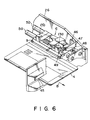
- Figs. 3 through 6 show main portions of the card reader-writers which are variations from the first embodiment of the present invention. Same components as those shown in Fig. 1 will be denoted by same reference numerals and description on these components will be omitted.
- the card reader-writer When arranged in this manner, the card reader-writer can attain same merits as those in the one shown in Fig. 1.
- a elastic member 43 such as rubber is attached to the chucking area of the upper claw 9 of the card chucking unit 6 and in the case of a third variation shown in Fig. 5, elastic matters 43 and 44 are achieved to chucking areas of the upper and lower claws 9 and 8.
- the card 4 When arranged in this manner, the card 4 can be more stably chucked between the upper and the lower claw due to the elastic matter 43 or elastic matters 43 and 44, thereby enabling the card 4 to be more stably conveyed, too.
- a system 46 for forcedly releasing the chucking operation of the card chucking unit 6 is located before the position at which the card chucking unit 6 is waiting, that is, on the side of a card inserting opening 45.
- the card 4 can be easily pulled out of the card reader-writer even if the card chucking unit 6 should not be opened because of power stop, for example, when the card 4 chucked by the card chucking unit 6 is returned to the waiting position of the system 6.
- the projection 13a is contacted with the roller 48 and lifted upward by the roller 48 as the card 4 is further pulled in the same direction.
- the upper claw 9 is swung to thereby allow the card 4 to be pulled out of the card reader-writer.
- Fig. 7 shows the card reader-writer according to a second embodiment of the present invention.
- This second embodiment of the present invention is designed for use with magnetic cards.
- a front panel 49 is located in front of the side plates 2a and 2b which form the frame 1.
- the front panel 49 is provided with a card inserting opening 45 through which the card 4 is inserted into the card reader-writer.
- Two guide rods 5a and 5b parallel to each other are arranged adjacent to the inner face of the side plate 2b and parallel to the card-inserting direction.
- the carriage 6A provided with the card chucking unit 6 is freely movably supported by the guide rods 5a and 5b.
- the card chucking unit 6 associates with the opening and closing system 14 to chuck the card 4 along the long one edge portion thereof in the thickness direction thereof.
- the base 7 of the card chucking unit 6 is freely movably supported by the guide rods 5a and 5b.
- the lower claw 8 is fixed to the base 7 and the upper claw 9 is located above the lower claw 8 and the base end of the upper claw 9 is freely swingably supported by the base 7.
- the upper claw 9 is urged toward the lower claw or in the closing direction by the urging springs.
- the pins 13a and 13b are mounted on the top of the portion 9A of the upper claw 9, erecting upward and parallel to the side plate 2b.
- the pins 13a and 13b are protruded toward the side plate 2b, and bearings 13c and 13d are mounted on the pins 13a and 13b, respectively.
- the upper claw 9 is controlled to swing toward and from the lower claw 8 by the opening and closing system 14 through the bearings 13c and 13d.
- the opening and closing system 14 includes the lever 15 and a stepping motor 52.
- the lever 15 is located above and parallel to the guide rod 5a and contacted with the undersides of the bearings 13c and 13d. Further, the lever 15 is attached to the rotary member 16 which extends along the inner face of the side plate 2b and which is freely swingably supported by the support members 18a, 18b and pins 18c, 18d.
- the guide member 22 for guiding the other free long edge portion of the card 4 to position the card 4 in the width direction thereof.
- a elastic sheet 22a having high coefficient of friction such as rubber is attached to the surface of the guide member 22, which contacts the side surface of the edge portion of the card 4, by adhesion.
- the guide member 22 is supported by a support lever 55, which is pivoted on the side plate 2a by mounting plates 55b, 55c and pins 55a.
- a drive solenoid 56 is connected to the lower end of the support lever 55 and the guide member 22 is driven by the solenoid 56.
- the motor 29 for conveying the card 4 is arranged below the guide rod 5a.
- the rotation force of this motor 29 is transmitted through the belts and the pulleys, as seen in the case of the first embodiment, to move the card chucking unit 6 along the guide rods 5a and 5b.
- a prehead 61 which is contacted with magnetic stripes on the underside (or top) of the card 4 to detect magnetism is located along and adjacent to the guide rod 5a and a magnetic head 57 which is contacted with magnetic stripes on the underside (or top) of the card 4 to read and write information is also located along and adjacent to the guide rod 5a.
- a card detecting sub-sensor (SW) 60, the prehead (PHD) 61 and a first card sensor (PD1) 62 which form a card checking unit for previously examining the card 4 inserted are arranged adjacent to the card inserting opening 45 of the card reader-writer.
- the card detecting sub-sensor 60 detects whether or not the card inserted has a predetermined width.
- the prehead 61 detects the magnetic stripes on the card 4 to confirm the direction in which the card 4 is directed.
- the first card sensor 62 detects the insertion of the card 4.
- a first carriage sensor (CRS1) 63 is arranged adjacent to the card checking unit to detect the position of the rear end of the retreated carriage 6A.
- a stopper solenoid (SOL1) 64 is arranged in front of the sensor 63 to prevent wrong cards from being inserted into the card reader-writer and to define the position of the card inserted.
- a card position adjusting section is located in front of the stopper solenoid 64.
- the card position adjusting section includes the card position adjusting solenoid (SOL2) 56, a second carriage sensor (CRS2) 66 and second and third card sensors (PD2 and PD3) 67 and 68.
- the second and third card sensors 67 and 68 are located one after another and adjacent to each other.
- the card 4 adjusted in position is detected by the second card sensor 67 to stop the advancing carriage 6A and the accurate relative positions of the card and the carriage are detected by the third card sensor 68 and the second carriage sensor 66 to position the card 4.
- the read/write and start position of the card 4 is set by the third card sensor 68.
- the card position adjusting solenoid (SOL2) 56 drives the guide member 22 to urge the card 4, which is in a position to be adjusted, traverse to adjust the position of the card 4 in the traverse direction.
- a fourth card sensor (PD4) 69 and a read/write head 57 are arranged in front of the card position adjusting section.
- the fourth card sensor 69 detects the card 4
- the read/write head 57 starts its reading and writing relative to the magnetic stripes on the card 4.
- the stepping motor (SMOT) 52 is arranged in front of and above the read/write head 57 and the carriage moving motor (CMOT) 29 is arranged below the read/write head 57.
- these sensors and actuators are connected to a controller 70 provided with a CPU.
- the carriage 6A provided with the card chucking unit 6 is waiting on the side of the card inserting opening 45 under normal state.
- the card chucking unit 6 is kept open.
- the state of the card 4 is detected by the card width detecting sub-sensor (SW) 60, the prehead (PHD) 61 and the first card sensor (PD1) 62. Signals applied from these sensors are sent to the controller 70 and when it is confirmed that the card is normal or right, the controller 70 makes the stopper solenoid (SOL1) 64 operative to open the card passage and half rotate the stepping motor 52 of the opening and closing system 14.
- the lever 15 is thus lowered and the card chucking unit 6 is closed to chuck the one long edge portion of the card 4 between the upper 9 and the lower claw 8 with a certain force.
- the motor 29 starts it rotation in the forward direction (MCF).
- the card chucking unit 6 is thus moved forward and the card 4 is also moved forward.
- the second card sensor (PD2) 67 detects the card 4 and the motor 29 is stopped while the stopper solenoid 64 is turned off in response to signal applied from the solenoid 67.
- the carriage 6A and the card 4 are then moved forward by inertia and when the third card sensor 68 detects the card 4, the motor 29 rotates in the backward direction (MCB) to stop the carriage 6A at the read/write and start position.
- the card holding solenoid 56 is made operative to swing the guide member 22, thereby adjusting the position of the card 4 in the traverse direction while holding the card 4 at the certain position (or read/write and start position).
- the stepping motor 52 operates to open the card chucking unit 6 and the motor 29 is then rotated backward to position the carriage 6A.
- the motor 29 is controlled this time in response to signal applied from the second carriage sensor 66.
- the card holding solenoid is turned off and the stepping motor again operates to close the card chucking unit 6.
- the motor 29 rotates in the forward direction (MCF) to move the card 4 forward. And the card 4 passes on the magnetic head 57 arranged on the card conveying passage.
- the fourth card sensor 69 detects the card 4 in this case, writing (or reading) of information is started on the magnetic stripes on the underside (or top) of the card 4.
- the first carriage sensor 63 detects the carriage 6A and the stepping motor 52 is half rotated to open the card chucking unit 6. A part of the card 4 is projected outside from the card inserting opening 45 under this state. Therefore, the card 4 can be pulled out of the card reader-writer by hand.
- the magnetic head is shown as an element for transmitting and receiving information to and from the card.
- a connective system for transmitting and receiving signals is provided in addition to the magnetic head.
- the urging springs for adding chucking force to the card chucking unit are selected depending upon what type of the card chucking unit is employed.
Landscapes
- Physics & Mathematics (AREA)
- General Physics & Mathematics (AREA)
- Engineering & Computer Science (AREA)
- Theoretical Computer Science (AREA)
- Conveying Record Carriers (AREA)
Applications Claiming Priority (2)
| Application Number | Priority Date | Filing Date | Title |
|---|---|---|---|
| JP147483/90 | 1990-06-07 | ||
| JP14748390 | 1990-06-07 |
Publications (3)
| Publication Number | Publication Date |
|---|---|
| EP0460606A2 true EP0460606A2 (de) | 1991-12-11 |
| EP0460606A3 EP0460606A3 (en) | 1992-12-02 |
| EP0460606B1 EP0460606B1 (de) | 1996-10-02 |
Family
ID=15431418
Family Applications (1)
| Application Number | Title | Priority Date | Filing Date |
|---|---|---|---|
| EP91109111A Expired - Lifetime EP0460606B1 (de) | 1990-06-07 | 1991-06-04 | Lese-/Schreibvorrichtung für eine Karte |
Country Status (4)
| Country | Link |
|---|---|
| US (1) | US5331144A (de) |
| EP (1) | EP0460606B1 (de) |
| KR (1) | KR920001388A (de) |
| DE (1) | DE69122428T2 (de) |
Cited By (1)
| Publication number | Priority date | Publication date | Assignee | Title |
|---|---|---|---|---|
| US11868835B2 (en) * | 2022-04-07 | 2024-01-09 | Capital One Services, Llc | Multi-part transaction card |
Families Citing this family (13)
| Publication number | Priority date | Publication date | Assignee | Title |
|---|---|---|---|---|
| KR100221199B1 (ko) * | 1997-03-31 | 1999-09-15 | 전주범 | 인터넷 셋탑 박스의 카드 및 디스크 캐리어 로딩장치 |
| US6032135A (en) * | 1997-04-29 | 2000-02-29 | Diebold, Incorporated | Electronic purse card value system terminal programming system and method |
| TW383119U (en) * | 1998-05-05 | 2000-02-21 | Ind Tech Res Inst | IC card/magnetic card compound reading machine |
| DE19952086A1 (de) * | 1999-10-29 | 2001-05-10 | Bosch Gmbh Robert | Transportvorrichtung für Chipkarten |
| EP1170692B1 (de) * | 2000-07-07 | 2009-03-25 | AMPHENOL-TUCHEL ELECTRONICS GmbH | Chipkarten-Lesegerät |
| DE10112061B4 (de) * | 2001-03-14 | 2007-08-30 | Siemens Ag | Aufnahmevorrichtung für in Fahrzeugen verwendete, der personenbezogenen Erfassung von Fahrtdaten dienende Chipkarten |
| EP1363227B1 (de) * | 2002-05-16 | 2006-04-19 | Compagnie Industrielle et Financiere d'Ingenierie Ingenico | Kartenlesevorrichtung |
| JP4064913B2 (ja) * | 2003-12-02 | 2008-03-19 | 日本電産サンキョー株式会社 | カードリーダ |
| US7017811B2 (en) * | 2004-05-18 | 2006-03-28 | Computerized Security Systems | Electronic card encoder |
| DE102004040448B4 (de) * | 2004-08-20 | 2010-01-21 | Amphenol-Tuchel Electronics Gmbh | Pushmatic Smart Card Connector |
| JP1521886S (de) * | 2014-08-20 | 2015-04-20 | ||
| CN107622602A (zh) * | 2017-09-29 | 2018-01-23 | 湖南长城信息金融设备有限责任公司 | 一种银行终端机柜上用的刷卡刷折结构 |
| CN112614275A (zh) * | 2021-01-08 | 2021-04-06 | 上海荨庄电子科技有限公司 | 一种保护电表插卡充费机 |
Family Cites Families (17)
| Publication number | Priority date | Publication date | Assignee | Title |
|---|---|---|---|---|
| US3631535A (en) * | 1968-07-26 | 1971-12-28 | Credit Systems Inc | Credit card decoder |
| US3984049A (en) * | 1975-04-04 | 1976-10-05 | NCR Canada Ltd. -- NCR Canada Ltee | Read-write head back-up member |
| DE2534578A1 (de) * | 1975-08-02 | 1977-02-10 | Licentia Gmbh | Automat mit einer einfuehrungsoeffnung |
| JPS5538713A (en) * | 1978-09-11 | 1980-03-18 | Kyodo Tsuushinshiya | Information processing system |
| EP0052661A1 (de) * | 1980-06-03 | 1982-06-02 | STORY, William Taylor | Debitkartenverfahren |
| EP0082175A1 (de) * | 1981-06-26 | 1983-06-29 | Michel Jean François Marie Widmer | Verfahren und integrierte einrichtung zur erfassung, verarbeitung und prüfung von zahlungsmitteln, wie schecks, magnetkarten und speicherkarten mittels eines transaktionsterminals |
| US4480181A (en) * | 1982-12-23 | 1984-10-30 | Fisher Charles R | Card capture device |
| GB2137393B (en) * | 1983-03-29 | 1986-02-05 | Burroughs Corp | Autoteller card-handling mechanism |
| DE3402632A1 (de) * | 1984-01-26 | 1985-08-01 | Siemens AG, 1000 Berlin und 8000 München | Verfahren und vorrichtung zur auswertung einer wertkarte in einem kartenleser |
| JP2542359B2 (ja) * | 1985-05-22 | 1996-10-09 | キヤノン株式会社 | 情報記録再生装置 |
| JPH0636266B2 (ja) * | 1985-10-18 | 1994-05-11 | キヤノン株式会社 | 情報記録再生装置 |
| JP2754530B2 (ja) * | 1986-07-25 | 1998-05-20 | オムロン株式会社 | カード処理装置 |
| JPS6391866A (ja) * | 1986-10-03 | 1988-04-22 | Sony Corp | 光カ−ド記録再生装置 |
| US4904852A (en) * | 1986-12-12 | 1990-02-27 | Omron Tateisi Electronics Co. | IC card reader |
| JPH01222391A (ja) * | 1987-11-27 | 1989-09-05 | Nhk Spring Co Ltd | 情報記憶カードリーダライタ |
| JPH0259992A (ja) * | 1988-08-26 | 1990-02-28 | Hiromasa Suekane | 燃料油プリペードカード処理装置つきガソリンスタンド |
| JPH0256094A (ja) * | 1988-08-19 | 1990-02-26 | Toshiba Corp | 取引装置 |
-
1991
- 1991-06-04 DE DE69122428T patent/DE69122428T2/de not_active Expired - Fee Related
- 1991-06-04 EP EP91109111A patent/EP0460606B1/de not_active Expired - Lifetime
- 1991-06-07 KR KR1019910009516A patent/KR920001388A/ko not_active Ceased
-
1993
- 1993-07-28 US US08/098,156 patent/US5331144A/en not_active Expired - Fee Related
Cited By (1)
| Publication number | Priority date | Publication date | Assignee | Title |
|---|---|---|---|---|
| US11868835B2 (en) * | 2022-04-07 | 2024-01-09 | Capital One Services, Llc | Multi-part transaction card |
Also Published As
| Publication number | Publication date |
|---|---|
| DE69122428D1 (de) | 1996-11-07 |
| EP0460606A3 (en) | 1992-12-02 |
| DE69122428T2 (de) | 1997-05-15 |
| US5331144A (en) | 1994-07-19 |
| KR920001388A (ko) | 1992-01-30 |
| EP0460606B1 (de) | 1996-10-02 |
Similar Documents
| Publication | Publication Date | Title |
|---|---|---|
| EP0460606B1 (de) | Lese-/Schreibvorrichtung für eine Karte | |
| US5499876A (en) | Printing apparatus having head gap adjusting device | |
| US3850299A (en) | Card transport and capture mechanism | |
| US6543685B1 (en) | Card processing apparatus for card encoder and printer therein | |
| GB2319375A (en) | Card reader | |
| JPS6261187A (ja) | 集積回路及び/又は磁気トラックを有するカード中のデータを読取るための混合型読取り装置 | |
| JPH0746369B2 (ja) | 身分証明カ−ド読取りエンコ−ダ | |
| KR920001669B1 (ko) | 책자류 취급장치, 책자류의 페이지넘기는 방법 및 책자류 프린터 | |
| JPH04228141A (ja) | カードリーダライタ | |
| JPS6057112B2 (ja) | 磁気カ−ド搬送装置 | |
| JP2690214B2 (ja) | 磁気カードリーダのカード寄せ装置 | |
| EP0809208B1 (de) | Verfahren und Vorrichtung zum Bedrucken eines Trägers und zum Erfassen und Lesen der auf dem Träger gedruckten Informationen | |
| US5491679A (en) | Information recording and/or reproducing apparatus with shutter member and shuttle linked for movement together | |
| JP3263260B2 (ja) | カードリーダのカードスタック装置 | |
| JP2908975B2 (ja) | カード取扱装置 | |
| JP2549805Y2 (ja) | 異巾カード兼用磁気カードリーダ | |
| JPH0519877Y2 (de) | ||
| JPH0248784A (ja) | カード処理装置 | |
| EP0794504B1 (de) | Verfahren und Vorrichtung zur Kontrolle von Kartenzuführung | |
| JPS596553Y2 (ja) | カ−ドリ−ダ−のリジエクト装置 | |
| JPH0844934A (ja) | 通帳印字装置および通帳印字方法 | |
| JPH01166285A (ja) | カード処理装置 | |
| JPS6316025Y2 (de) | ||
| JP2518543Y2 (ja) | 情報読出書込装置 | |
| JP2947925B2 (ja) | 封筒及び単一シート預入装置 |
Legal Events
| Date | Code | Title | Description |
|---|---|---|---|
| PUAI | Public reference made under article 153(3) epc to a published international application that has entered the european phase |
Free format text: ORIGINAL CODE: 0009012 |
|
| 17P | Request for examination filed |
Effective date: 19910604 |
|
| AK | Designated contracting states |
Kind code of ref document: A2 Designated state(s): DE FR GB |
|
| PUAL | Search report despatched |
Free format text: ORIGINAL CODE: 0009013 |
|
| AK | Designated contracting states |
Kind code of ref document: A3 Designated state(s): DE FR GB |
|
| 17Q | First examination report despatched |
Effective date: 19940928 |
|
| GRAH | Despatch of communication of intention to grant a patent |
Free format text: ORIGINAL CODE: EPIDOS IGRA |
|
| GRAH | Despatch of communication of intention to grant a patent |
Free format text: ORIGINAL CODE: EPIDOS IGRA |
|
| GRAA | (expected) grant |
Free format text: ORIGINAL CODE: 0009210 |
|
| AK | Designated contracting states |
Kind code of ref document: B1 Designated state(s): DE FR GB |
|
| PG25 | Lapsed in a contracting state [announced via postgrant information from national office to epo] |
Ref country code: FR Effective date: 19961002 |
|
| REF | Corresponds to: |
Ref document number: 69122428 Country of ref document: DE Date of ref document: 19961107 |
|
| EN | Fr: translation not filed | ||
| PG25 | Lapsed in a contracting state [announced via postgrant information from national office to epo] |
Ref country code: GB Free format text: LAPSE BECAUSE OF NON-PAYMENT OF DUE FEES Effective date: 19970604 |
|
| PLBE | No opposition filed within time limit |
Free format text: ORIGINAL CODE: 0009261 |
|
| STAA | Information on the status of an ep patent application or granted ep patent |
Free format text: STATUS: NO OPPOSITION FILED WITHIN TIME LIMIT |
|
| 26N | No opposition filed | ||
| GBPC | Gb: european patent ceased through non-payment of renewal fee |
Effective date: 19970604 |
|
| PGFP | Annual fee paid to national office [announced via postgrant information from national office to epo] |
Ref country code: DE Payment date: 20010528 Year of fee payment: 11 |
|
| PG25 | Lapsed in a contracting state [announced via postgrant information from national office to epo] |
Ref country code: DE Free format text: LAPSE BECAUSE OF NON-PAYMENT OF DUE FEES Effective date: 20030101 |