EP0461903B1 - Appareil de traitement d'images utilisant un réseau neuronal - Google Patents
Appareil de traitement d'images utilisant un réseau neuronal Download PDFInfo
- Publication number
- EP0461903B1 EP0461903B1 EP91305365A EP91305365A EP0461903B1 EP 0461903 B1 EP0461903 B1 EP 0461903B1 EP 91305365 A EP91305365 A EP 91305365A EP 91305365 A EP91305365 A EP 91305365A EP 0461903 B1 EP0461903 B1 EP 0461903B1
- Authority
- EP
- European Patent Office
- Prior art keywords
- image data
- pixel
- interest
- multivalued
- neural network
- Prior art date
- Legal status (The legal status is an assumption and is not a legal conclusion. Google has not performed a legal analysis and makes no representation as to the accuracy of the status listed.)
- Expired - Lifetime
Links
Images





Classifications
-
- G—PHYSICS
- G06—COMPUTING OR CALCULATING; COUNTING
- G06N—COMPUTING ARRANGEMENTS BASED ON SPECIFIC COMPUTATIONAL MODELS
- G06N3/00—Computing arrangements based on biological models
- G06N3/02—Neural networks
- G06N3/04—Architecture, e.g. interconnection topology
- G06N3/045—Combinations of networks
-
- G—PHYSICS
- G06—COMPUTING OR CALCULATING; COUNTING
- G06N—COMPUTING ARRANGEMENTS BASED ON SPECIFIC COMPUTATIONAL MODELS
- G06N3/00—Computing arrangements based on biological models
- G06N3/02—Neural networks
- G06N3/04—Architecture, e.g. interconnection topology
- G06N3/0499—Feedforward networks
-
- G—PHYSICS
- G06—COMPUTING OR CALCULATING; COUNTING
- G06N—COMPUTING ARRANGEMENTS BASED ON SPECIFIC COMPUTATIONAL MODELS
- G06N3/00—Computing arrangements based on biological models
- G06N3/02—Neural networks
- G06N3/08—Learning methods
- G06N3/09—Supervised learning
Definitions
- This invention relates to an image processing apparatus which utilizes a neural network to execute processing for restoring an original multivalued image from a binarized image.
- One conventional method of executing processing for restoring an original multivalued image from a binarized image is to use a smoothing filter circuit which applies smoothing to an area having a rectangular shape.
- Another method that has been proposed is to store the results of processing by a smoothing filter in a ROM or RAM as a LUT (look-up table) beforehand in order to reduce circuitry and raise processing speed, and then refer to this table when image processing is performed.
- LUT look-up table
- Fig. 1 illustrates a prior-art example of a multiple-value converting apparatus using a LUT which performs the same function as a 3 x 3 filter.
- the apparatus includes a line buffer 701 comprising FIFO memories or the like.
- the line buffer 701 receives an input of binary data from an image input unit (not shown) and accumulates three raster lines of data.
- a data latch 702 latches three pixels of data for every line from among the three lines of data delivered by the line buffer 701.
- Binary image data corresponding to a 3 x 3 window is obtained from the data latch 702.
- a method contemplated to solve this problem is to discriminate among areas to convert fine-line portions and image portions to multiple values separately.
- the state of the art is such that a method of image discrimination based upon binary image data has not yet been established.
- the present assignee has proposed, in European Application No. 91302488.1, an image processing method using a neural network.
- This proposed method entails providing a rectangular window area the center of which is a pixel of interest with regard to restoration, and estimating multivalued data from the binary pattern of an input corresponding to this area by utilizing a neural network.
- the aforesaid window is provided, however, good results cannot be obtained unless the window is large in size.
- a problem that arises when a large window is provided is that the pixels to be referred to are excessive in number.
- the fact that there are a large number of pixels to be referred to results in hardware-related difficulties from the viewpoint of processing speed and the size of the circuitry.
- an object of the present invention is to provide an image processing apparatus using a neural network in which it is possible to reduce the number of pixels to be referred to in processing.
- an image processing apparatus for estimating multivalued image data from binarised image data comprises input means for inputting binary image data comprising a plurality of pixels which include a pixel of interest that is to be subjected to multivalued conversion, these plurality of pixels being contained in an area that is asymmetrical with respect to the position of the pixel of interest; and multivalued converting means for executing processing, by a neural network, to restore the inputted binary image data to multivalued image data of the pixel of interest.
- the processed area is of an asymmetrical form containing more pixels to the left of the pixel of interest than to the right thereof.
- the processed area is of an asymmetrical form containing more pixels above the pixel of interest than below.
- the binary input data is binarized by an error diffusion method.
- an error produced with regard to the pixel of interest is diffused from the position of this pixel of interest toward pixels at positions having an asymmetric distribution.
- the above-mentioned area has a size of 4 x 4, and the pixel of interest is located at position (3,3).
- the above-mentioned area has a size of 5 x 5, and the pixel of interest is located at position (4,4).
- the above-mentioned area is of an asymmetrical form containing more pixels to the upper left of the pixel of interest than to the lower right thereof.
- the neural network has one input layer, one intermediate layer and one output layer.
- an image processing apparatus for restoring a binary image in which a fine-line and a portions and an image portion are mixed, comprising: discriminating means for discriminating inputted binary image data by a first neural network to determine whether the image data is indicative of the fine-line and a character portions or the image portion; first restoring means for applying multivalued restoration processing, by a second neural network, to the fine-line and character portions contained in the inputted binary image data; second restoring means for applying multivalued restoration processing, by a third neural network, to the image portion contained in the inputted binary image data; and control means for performing control based upon the results of discrimination by the discriminating means in such a manner that the multivalued restoration processing is executed by either the first or second restoring means.
- image discrimination is performed using a neural network to determine whether the input data is indicative of the fine line and character portions or of an image portion. Based upon the results of discrimination, a multivalued conversion is performed by the multivalued converting means provided for the character portion or image portion. As a result, the fine-line and character portions are subjected to a multivalued conversion while preserving the edge of the character. In case of a half-tone image, the image is subjected to a multivalued conversion while the graininess produced by binarization is eliminated. Accordingly, the original multivalued image can be reproduced with considerable accuracy. In addition, since image discrimination regarding character portions and image portions is carried out by a neural network, the discrimination takes into account the positional relationship among dots as well as connecting information, unlike processing by the conventional filter. This makes possible considerably accurate image reconstruction.
- the number of referential pixels of the first neural network of the discriminating means is greater than the numbers of referential pixels of the second and third neural networks of the first and second restoring means, respectively.
- the first, second and third neural networks are replaced by tables when coupling coefficients with in the neural networks are decided by learning.
- Another object of the present invention is to provide a learning method in an image processing apparatus using a neural network to restore image data, which contains a mixture of fine-line portions and half-tone image portions, to multivalued image data, wherein the learning is performed in an efficient manner.
- the foregoing object is attained by providing a learning method in an image processing apparatus comprising: input means for inputting binary image data; first restoring means for applying multivalued restoration processing, by a first neural network, to a fine-line and character portions contained in the inputted binary image data; and second restoring means for applying multivalued restoration processing, by a second neural network, to an image portion contained in the inputted binary image data;
- the learning method comprising: a step of preparing inputs of binary image data and of ideal output data each containing a fine-line and character portions and a half-tone portion; a step of preparing a map which contains data indicating whether a portion is the fine-line portion or the half-tone portion in the binary image data and ideal output data; and a step of inputting the inputs of input binary image data and of the ideal output data to either of the two neural networks based upon values in the map, and learning coupling coefficients between neurons of the neural network to which the data has been inputted.
- the items of input binary image data and ideal output data are made to share the same fine-line portion and half-tone portion, and which of the first and second neural networks is to undergo learning is decided based upon the values in the map.
- Fig. 5 is a block diagram illustrating the construction of the apparatus.
- the apparatus includes a line buffer 101 comprising FIFO memories or the like.
- the line buffer 101 receives an input of binary data from an image input unit (not shown) and accumulates seven raster lines of data.
- a data latch 102 latches seven pixels of data for every line from among the seven lines of data delivered by the line buffer 101.
- the pixel marked by the "*" symbol is the pixel of interest.
- the data of 49 bits enters an image discriminating circuit 103.
- the latter outputs "0" when the 49-bit data is indicative of a half-tone image, and "1" when the 49-bit data is indicative of a fine-line portion.
- This output value shown at numeral 113, is a selection control signal applied to a selector 107.
- a data latch 104 From among the outputs produced by the line buffer 101, those on the five centrally located lines are supplied to a data latch 104.
- This 25-bit data enters both a multivalued converting circuit 105 for half-tone images and a multivalued converting circuit 106 for fine lines.
- the multivalued converting circuits 105, 106 each output one items of eight-bit multivalued data. These outputs enter the selector 107.
- the latter which is under the control of the control signal 113 from the image discriminating circuit 103, operates so as to deliver the output data of the multivalued converting circuit 105 when the result of image discrimination indicates a half-tone image, and the output data of the multivalued converting circuit 106 when the result of image discrimination indicates a fine line.
- the foregoing units are under the control of a CPU, which is not shown.
- a so-called neural chip employing a neural network is used in the image discriminating circuit 103, the multivalued converting circuit 105 for half-tone images, and the multivalued converting circuit 106 for fine lines.
- the image processing apparatus of Fig. 5 has the following characterizing features:
- a neural network In a case where a neural network is used in data processing, learning accuracy is affected by processing accuracy.
- Learning in a neural network refers to optimizing the coupling coefficients between neurons. Once learning has been completed, the prescribed data processing can be expected if the coupling coefficients are set (fixed) at their optimum values. When the coupling coefficients have been fixed, it is possible for arithmetic operations in the neurons of the neural network to be put into the form of a ROM (or table).
- a general procedure for back-propagation-type learning in a neural network will be described taking a neural network shown in Fig. 6 as an example.
- the neural network illustrated in Fig. 6 has an input layer 201 (composed of i-number of neurons) which produces outputs (i-out) 204 that enter an intermediate layer 202 (composed of j-number of neurons) comprising a signal layer.
- the intermediate layer 202 produces outputs (j-out) 205 that enter an output layer 203 (composed of k-number of neurons), which delivers outputs (k-out) 206.
- Ideal outputs (ideal-out) are shown at numeral 207.
- the number i of neurons in the input layer 201 will be 49.
- the number i of neurons will be 25.
- the neural network of Fig. 6 is configured to show the general character of a neural network.
- the coupling between one neuron and the neurons in another layer is represented by the solid lines.
- the coupling between two layers specifically means that the output of a neuron in the preceding layer is inputted to neurons in the succeeding layer, where the output is subjected to an arithmetic operation.
- the small circles in Fig. 6 represent arithmetic operations based upon a coupling coefficient W.
- Learning in a neural network refers to deciding the coupling coefficient W ji between the input and intermediate layers and the coupling coefficient W kj between the intermediate and output layers.
- the input data for learning and the corresponding ideal output (ideal-out) are prepared in advance, and the initial values of the coupling coefficient W ji in the intermediate layer and the coupling coefficient W kj in the output layer are decided appropriately. This is the preliminary stage of learning.
- the prepared input data is applied to the network coupled based upon the initial values, whereupon these items of data are processed in the intermediate layer to obtain the outputs (j-out) 205 from the intermediate layer.
- the outputs are applied to the output layer 203 (composed of k-number of neurons), which delivers the outputs (k-out) 206.
- the procedure up to this point is indicated by the flow of arrows A and B in Fig. 6.
- the outputs (k-out) 206 obtained from the output layer and the prepared ideal outputs (ideal-out) 207 are compared, a teach signal (a teach signal for the output layer) is generated by the comparison, and the coupling coefficient W kj in the output layer is corrected by the teach signal.
- a teach signal for the intermediate layer is generated to correct the coupling coefficient W ji in the intermediate layer. This is the process indicated by arrow D in Fig. 6.
- the coupling coefficients W ji , W kj are successively corrected toward appropriate values.
- the updated coupling coefficients are maintained within the network.
- Learning is stipulated by the "input data” and "ideal output” prepared. If the "ideal output” is multivalued image data and the "input data” is data obtained by binarizing this multivalued image data, then a neural network which has undergone learning based upon these items of data should function as a network appropriate for converting a binary image into a multivalued image (i.e., as a network appropriate for restoring a multivalued image from a binary image).
- step S402 the initial values of weighting coefficients (coupling strengths) W ji , W kj are applied. In consideration of convergence in the learning process, values in the range -0.5 to +0.5 are selected.
- step S404 input data iout(i) for learning is selected, and this data iout(i) is set in the input layer at step S406. If this network is to be utilized in image processing, the input data iout(i) is image data of one pixel. An ideal output (ideal-out) corresponding to the input data iout(i) is prepared at step S408. The foregoing steps constitute the preliminary stage.
- step S411 the output kout(k) of the output layer is obtained at step S411.
- kout(k)* ⁇ 1 - kout(k) ⁇ is defined as the differential of the sigmoid function kout(k).
- ⁇ represents a constant referred to as a stabilizing constant
- ⁇ represents a constant referred to as a learning constant.
- step S416 the teach signal teach_j(j) of the intermediate layer is computed.
- the contribution in the backward direction from the output layer to each element of the intermediate layer is computed based upon
- learning is performed.
- step S422 It is determined at step S422 whether the foregoing learning has been carried out with regard to all input data. If learning is still incomplete, the processing of steps S402 through S420 is repeated.
- step S424 It is determined at step S424 whether the number of learning cycles has attained the prescribed number. If the number of learning cycles is still inadequate, the processing of steps S402 through S422 is repeated.
- the foregoing is a description of a learning procedure of a common neural network based upon the back-propagation method.
- the learning described above constitutes a preliminary stage for image processing. In actual image processing, only the coupling coefficients obtained are used.
- This learning is applied to the three neural networks of the image processing apparatus illustrated in Fig. 5.
- the image processing apparatus of Fig. 5 will act as a neural network system capable of restoring a multivalued image while fine-line and character portions are discriminated from half-tone image portions.
- Figs. 6, 7A and 7B illustrate the general learning procedure for a neural network.
- some specialization is necessary to bring the description of Figs. 7A and 7B into conformity with the system of Fig. 5. This specialization will now be described.
- the learning input data for the image discriminating neural chip 103 is composed of 49 pixels (having logic values of "0" or "1") in a 7 x 7 window the center of which is the pixel of interest. (These pixels are from the binary image data.) Accordingly, the number of neurons in the input layer of the image discriminating neural chip 103 is 49. Since the image discriminating neural chip 103 should output "1" when the input image is a fine-line portion and "0" when the input image is a half-tone image portion, the number of neurons in the output layer is one. There can be any number of neurons in the intermediate layer, though the number is 25 in this embodiment.
- Fig. 8A illustrates an example of input data for learning.
- This example illustrates a binary image obtained by binarizing, using a predetermined binarizing method, an original image in which characters "ABCDEFG" are written at the upper left and a photograph of a human being appears at the lower right.
- a map of binary values ("1" and "0") of the kind shown in Fig. 8B or 8C is prepared as ideal output data for learning.
- the example of Fig. 8B is a map obtained by applying an edge detecting filter to an original multivalued image.
- FIG. 8C is a map in which an area is designated artificially.
- the difference between the ideal output data of Fig. 8B and that of Fig. 8C is that fine-line (edge) portions are set at the periphery of the character portions and at the periphery of the photograph of the human being in Fig. 8B, whereas the entirety of the character portions are made fine-line portions and all other portions are made half-tone image portions in Fig. 8C.
- a learning pixel is selected randomly, a 7 x 7 window having this pixel at its center is proved, and the pixels in this window are adopted as the input data. This is illustrated in Fig. 9.
- the learning procedure described in connection with Figs. 7A and 7B is executed using this learning data, the procedure is repeated until the learning values converge, and the coupling coefficients which prevail at convergence are decided as the parameters of image discrimination for the neural chip 103.
- outputs of 0 - 1.0 are obtained from the output layer of the chip 103.
- An image is determined to be a fine-line portion when output ⁇ 0.5 holds and a half-tone image when output ⁇ 0.5 holds.
- a characterizing feature of learning in the multivalued converting neural chips according to this embodiment is that common use is made of the ideal output data employed in both of these chips.
- a multivalued image (an image of the kind shown in Fig. 10B, for example) is used as the ideal output, and then an image (the image of Fig. 10A), which is obtained by binarizing the multivalued image using a prescribed method of binarization processing, is used as the input data.
- the 25 items of data in a 5 x 5 window having the pixel of interest as its center are used in order to perform the multivalued conversion both when an image is a fine-line portion and when an image is a half-tone image portion.
- the number of input-layer neurons in each of the neural networks 105 and 106 is 25, and the number of neurons in the output layer in these networks is one.
- the intermediate layer can have any number of neurons, the number is 15 in this embodiment.
- a pixel of interest (indicated by "*") is randomly selected in the image of Fig. 10A, a 5 x 5 window having this pixel at its center is provided, and the binary image data within this window is adopted as the input data.
- the items of input data and ideal output data used in learning of the neural network 105 for multivalued conversion of a half-tone portion and in learning of the neural network 106 for fine-line portions are peculiar to each learning process. Accordingly, consideration has been given to adopting common data for the input data and ideal output data used in the learning processes of the neural chips 105, 106. The reason is that if common data can be employed, this will make it possible to perform learning in the two neural chips simultaneously. To attain this goal, it is necessary to prepare a map which indicates whether the origins of the input data and ideal output data are a fine-line portion or half-tone portion. Such a map is illustrated in Fig. 10C. This map corresponds to the image discrimination maps shown in Figs.
- the map has a "1" if the result of discrimination indicates a fine line and a "0" if the result of discrimination indicates a half-tone.
- step S412 in the map corresponding to the pixel at the "*" position in Fig. 10A is "0". How the other control steps will change if the items of input data and ideal output data are rendered common will be described with reference to Fig. 7D using step S412 as an example.
- step S412a it is determined at step S412a whether the map value is "0" or "1".
- ideal_out(k) represent an ideal output that has been made common; let teach_k E (k) and kout E (k) represent the teach signal and an intermediate-layer output for a fine-line portion, respectively; and let teach_k H (k) and kout H (k) represent the teach signal and an intermediate-layer output for a half-tone portion.
- learning of the coupling coefficients in image discrimination can be executed by a 5 x 5 window having the pixel of interest at its center. This will make it possible to raise processing speed, although there will be a slight decline in accuracy. Conversely, it is also possible to enlarge the size of the window. Further, window size can be changed for every target area even in multivalued conversion. For example, a 7 x 7 can be used for half-tones and a 5 x 5 window for fine-line portions.
- the image processing apparatus of Fig. 5 estimates the original multivalued image from the binary image and performs a multivalued restoration.
- the number of pixels referred to at the time of estimation is reduced in a case where the binarizing method is of the information preserving type, such as the error diffusion method.
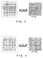
- the input data is constituted by the values ("0"s or "1"s) of 16 pixels in a 4 x 4 window of the image data binarized using the error diffusion method. Accordingly, the neurons of the input layer are 16 in number, and there is only one neuron in the output layer because the multivalued output is that for a single pixel. Though the intermediate layer can have any number of neurons, the number is 12 in this embodiment.
- the data is constituted by multivalued image data, namely the original image composed of binarized input data for learning.
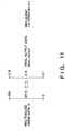
- the pixel of interest is selected at random, a 4 x 4 window is provided, as in Fig. 11, with respect to this pixel, and the data of the pixels in the window is given.
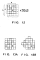
- the 4 x 4 window bounded by the solid line in Fig. 12 contains many pixels above and to the left of the pixel of interest, which is represented by the "*" symbol.
- the fifth-row and fifth column of pixels are unnecessary. That is, there are nine fewer referential pixels in comparison with the neural networks according to the embodiment of Fig. 5.
Landscapes
- Engineering & Computer Science (AREA)
- Theoretical Computer Science (AREA)
- Physics & Mathematics (AREA)
- General Health & Medical Sciences (AREA)
- Computing Systems (AREA)
- Biomedical Technology (AREA)
- Biophysics (AREA)
- Computational Linguistics (AREA)
- Data Mining & Analysis (AREA)
- Evolutionary Computation (AREA)
- Life Sciences & Earth Sciences (AREA)
- Molecular Biology (AREA)
- Artificial Intelligence (AREA)
- General Engineering & Computer Science (AREA)
- General Physics & Mathematics (AREA)
- Mathematical Physics (AREA)
- Software Systems (AREA)
- Health & Medical Sciences (AREA)
- Facsimile Image Signal Circuits (AREA)
- Image Analysis (AREA)
- Image Processing (AREA)
Claims (15)
- Appareil de traitement d'image pour estimer des données d'image à valeurs multiples à partir de données d'image mises sous forme binaire, comprenant :un moyen d'entrée pour recevoir des données d'image binaires comprenant une pluralité de pixels contenus dans une zone qui comporte un pixel intéressant qui doit être soumis à un traitement en vue d'estimer des données d'image à valeurs multiples, la zone étant déterminée en fonction de la position (*) du pixel intéressant ; etun moyen de conversion pour traiter les données d'image binaires reçues de ladite zone en vue de générer des données d'image à valeurs multiples du pixel intéressant,dans lequel la zone traitée contenant les données d'image binaires reçues est asymétrique par rapport à la position (*) du pixel intéressant, contenant plus de pixels à la gauche du pixel intéressant qu'à sa droite, et/ou contenant plus de pixels au-dessus du pixel intéressant qu'au-dessous de celui-ci, les données d'image binaires étant reçues suivant une séquence de gauche à droite et de haut en bas (figures 12, 13A, 13B),dans lequel ledit moyen de conversion convertit les données d'image binaires introduites en utilisant un réseau neuronal, etdans lequel le réseau neuronal est le produit direct ou indirect d'un apprentissage effectué de la façon suivante:en préparant les données d'image binaires et les données d'image à valeurs multiples d'une image ; eten pourvoyant le réseau neuronal d'une pluralité de pixels des données d'image binaires préparées contenues dans une zone déterminée en fonction de la position du pixel intéressant en tant qu'entrée pour l'apprentissage, et les données d'image à valeurs multiples préparées correspondant au pixel intéressant en tant que sortie idéale pour l'apprentissage.
- Appareil selon la revendication 1, dans lequel la zone traitée contient plus de pixels à la gauche du pixel intéressant qu'à la droite de celui-ci.
- Appareil selon la revendication 1 ou 2, dans lequel la zone traitée contient plus de pixels au-dessus du pixel intéressant qu'au-dessous de celui-ci.
- Appareil selon la revendication 1, 2 ou 3, dans lequel le moyen d'entrée est apte à recevoir des données d'image binaires qui ont été mises sous forme binaire par un procédé de diffusion d'erreur dans lequel des erreurs par pixel sont réparties vers le bas et vers la droite.
- Appareil selon la revendication 1, 2, 3 ou 4, dans lequel la zone traitée a un format de 4 x 4, et le pixel intéressant est situé dans la position (3, 3).
- Appareil selon la revendication 1, 2, 3 ou 4, dans lequel la zone traitée a un format de 5 x 5, et le pixel intéressant est situé dans la position (4, 4).
- Appareil selon la revendication 1, 2, 3 ou 4, dans lequel la zone traitée contient plus de pixels à la partie supérieure gauche du pixel intéressant qu'à la partie inférieure droite de celui-ci.
- Appareil selon l'une quelconque des revendications précédentes, dans lequel ledit réseau neuronal comprend :une couche d'entrée qui comporte une pluralité de neurones pour introduire les données d'image binaires d'entrée en unités de pixel individuelles ;une couche intermédiaire qui comporte une pluralité de neurones connectés aux neurones de ladite couche d'entrée ; etune couche de sortie ayant un neurone connecté aux neurones de ladite couche intermédiaire.
- Appareil selon l'une quelconque des revendications précédentes, dans lequel ledit moyen de conversion de valeurs multiples comprend :un moyen de discrimination (102, 103) pour discriminer les données d'image binaires introduites par un premier réseau neuronal (103) en vue de déterminer si les données d'image sont indicatrices d'une ligne fine et de parties d'un caractère ou d'une partie d'image ;un premier moyen de restauration pour appliquer un traitement de restauration de valeurs multiples, par un deuxième réseau neuronal (106), aux parties de ligne fine et de caractère contenues dans les données d'image binaires introduites ;un deuxième moyen de restauration pour appliquer un traitement de restauration de valeurs multiples, par un troisième réseau neuronal (105), à la partie d'image contenue dans les données d'image binaires introduites ; etun moyen de commande (107) pour conduire le traitement de restauration de valeurs multiples à être exécuté par un moyen approprié parmi lesdit premier et ledit deuxième moyens de restauration, sur la base des résultats d'une discrimination effectuée par ledit moyen de discrimination.
- Appareil selon la revendication 9, dans lequel le nombre de pixels de référence dudit premier réseau neuronal (103) est supérieur aux nombres de pixels de référence dudit deuxième et dudit troisième réseaux neuronaux (106, 105).
- Appareil selon l'une quelconque des revendications précédentes, dans lequel l'apprentissage dans ledit réseau neuronal est effectué selon un procédé de propagation vers l'arrière.
- Appareil selon l'une quelconque des revendications précédentes, dans lequel le réseau neuronal dans ledit moyen de conversion est remplacé par une table de conversion qui délivre la même valeur que le réseau neuronal pour chacune de ses entrées.
- Appareil selon l'une quelconque des revendications précédentes, dans lequel la sortie idéale est constituée de données d'image à valeurs multiples originales à partir desquelles l'image binaire à été convertie.
- Procédé de traitement d'image pour estimer des données d'image à valeurs multiples à partir de données d'image mises sous forme binaire, comprenant les étapes suivantes :réception de données d'image binaires comprenant une pluralité de pixels contenus dans une zone, qui comportent un pixel intéressant qui doit être traité pour une estimation des données d'image à valeurs multiples, la zone étant déterminée en fonction de la position (*) du pixel intéressant ; etconversion des données d'image binaires reçues de ladite zone en les traitant en données d'image à valeurs multiples du pixel intéressant,dans lequel la zone traitée contenant les données d'image binaires reçues est asymétrique par rapport à la position (*) du pixel intéressant, contenant plus de pixels à la gauche du pixel intéressant qu'à sa droite, et/ou contenant plus de pixels au-dessus du pixel intéressant qu'au-dessous de celui-ci, les données d'image binaires étant reçues suivant une séquence de gauche à droite et de haut en bas (figures 12, 13A, 13B),dans lequel l'étape de conversion est exécutée en utilisant un réseau neuronal, et dans lequel le réseau neuronal est le produit direct ou indirect d'un apprentissage effectué :en préparant des données d'image binaires et des données d'image à valeurs multiples d'une image ; eten pourvoyant le réseau neuronal d'une pluralité de pixels des données d'image binaires préparées contenues dans une zone déterminée en fonction de la position du pixel intéressant en tant qu'entrée pour l'apprentissage, et avec les données d'image à valeurs multiples préparées du pixel intéressant en tant que sortie idéale pour l'apprentissage.
- Signal transportant des données d'image à valeurs multiples d'une pluralité de pixels, les données d'image à valeurs multiples ayant été converties à partir de données d'image binaires reçues par le procédé selon la revendication 14.
Applications Claiming Priority (6)
| Application Number | Priority Date | Filing Date | Title |
|---|---|---|---|
| JP2153935A JP2859377B2 (ja) | 1990-06-14 | 1990-06-14 | ニューラルネットを用いた画像処理方法および画像処理装置 |
| JP153935/90 | 1990-06-14 | ||
| JP2161902A JP2810497B2 (ja) | 1990-06-19 | 1990-06-19 | 画像処理装置 |
| JP161901/90 | 1990-06-19 | ||
| JP161902/90 | 1990-06-19 | ||
| JP2161901A JPH0451374A (ja) | 1990-06-19 | 1990-06-19 | 画像処理装置 |
Publications (3)
| Publication Number | Publication Date |
|---|---|
| EP0461903A2 EP0461903A2 (fr) | 1991-12-18 |
| EP0461903A3 EP0461903A3 (en) | 1993-09-15 |
| EP0461903B1 true EP0461903B1 (fr) | 1997-09-03 |
Family
ID=27320561
Family Applications (1)
| Application Number | Title | Priority Date | Filing Date |
|---|---|---|---|
| EP91305365A Expired - Lifetime EP0461903B1 (fr) | 1990-06-14 | 1991-06-13 | Appareil de traitement d'images utilisant un réseau neuronal |
Country Status (3)
| Country | Link |
|---|---|
| US (1) | US5309525A (fr) |
| EP (1) | EP0461903B1 (fr) |
| DE (1) | DE69127510T2 (fr) |
Families Citing this family (22)
| Publication number | Priority date | Publication date | Assignee | Title |
|---|---|---|---|---|
| EP0461902B1 (fr) | 1990-06-14 | 1998-12-23 | Canon Kabushiki Kaisha | Réseau neuronal |
| US6259824B1 (en) | 1991-03-12 | 2001-07-10 | Canon Kabushiki Kaisha | Image processing apparatus utilizing a neural network to improve printed image quality |
| US5838834A (en) * | 1991-11-07 | 1998-11-17 | Canon Kabushiki Kaisha | Image processing apparatus and method for quantizing image data and quantization errors using single quantizing unit and pluralities of quantization tables |
| DE69331126T2 (de) * | 1992-07-31 | 2002-06-20 | Canon K.K., Tokio/Tokyo | Bildverarbeitungsgerät und Verfahren zur mehrstufigen Kompression |
| US6028961A (en) * | 1992-07-31 | 2000-02-22 | Canon Kabushiki Kaisha | Image processing method and apparatus |
| US5617484A (en) * | 1992-09-25 | 1997-04-01 | Olympus Optical Co., Ltd. | Image binarizing apparatus |
| US5479570A (en) * | 1992-10-06 | 1995-12-26 | Matsushita Electric Industrial Co., Ltd. | Learning and recognition machine |
| JP2509860B2 (ja) * | 1993-03-08 | 1996-06-26 | 株式会社エイ・ティ・アール視聴覚機構研究所 | パタ―ン生成装置 |
| CN1092446C (zh) * | 1993-05-31 | 2002-10-09 | 佳能株式会社 | 图象处理方法和装置 |
| WO1995005640A1 (fr) * | 1993-08-13 | 1995-02-23 | Kokusai Denshin Denwa Co., Ltd. | Reseau neuronal multivalue parallele |
| JP2673871B2 (ja) * | 1993-08-26 | 1997-11-05 | 日本アイ・ビー・エム株式会社 | ニューラル・ネットワークによるパターン認識方法及び装置 |
| US5729623A (en) * | 1993-10-18 | 1998-03-17 | Glory Kogyo Kabushiki Kaisha | Pattern recognition apparatus and method of optimizing mask for pattern recognition according to genetic algorithm |
| JPH0981723A (ja) * | 1995-09-08 | 1997-03-28 | Canon Inc | 画像処理装置 |
| US6075884A (en) * | 1996-03-29 | 2000-06-13 | Sarnoff Corporation | Method and apparatus for training a neural network to learn and use fidelity metric as a control mechanism |
| WO1997039417A2 (fr) * | 1996-03-29 | 1997-10-23 | Sarnoff Corporation | Methode et dispositif pour entrainer un reseau de neurones a apprendre et a utiliser la metrique de fidelite comme mecanisme de controle |
| JP3184092B2 (ja) * | 1996-05-27 | 2001-07-09 | シャープ株式会社 | 画像処理方法 |
| JP3476331B2 (ja) * | 1997-03-14 | 2003-12-10 | 株式会社東芝 | 画像処理装置および画像処理方法 |
| US6307978B1 (en) | 1998-06-03 | 2001-10-23 | Wellesley College | System and method for parallel error diffusion dithering |
| JP4247639B2 (ja) * | 2006-06-14 | 2009-04-02 | セイコーエプソン株式会社 | 印刷用色変換プロファイルの生成 |
| KR102113462B1 (ko) * | 2017-02-09 | 2020-05-21 | 미쓰비시덴키 가부시키가이샤 | 위치 제어 장치 및 위치 제어 방법 |
| DE112017007028B4 (de) * | 2017-02-09 | 2023-06-15 | Mitsubishi Electric Corporation | Positionskontrollvorrichtung und Positionskontrollverfahren |
| JP7254621B2 (ja) * | 2019-05-21 | 2023-04-10 | キヤノン株式会社 | 画像処理装置、学習装置、画像処理方法、学習方法、及びプログラム |
Family Cites Families (9)
| Publication number | Priority date | Publication date | Assignee | Title |
|---|---|---|---|---|
| JPS6313578A (ja) * | 1986-07-04 | 1988-01-20 | Canon Inc | 多値化方法 |
| JPS6318403A (ja) | 1986-07-10 | 1988-01-26 | Fanuc Ltd | オフライン制御実行方法 |
| US4829587A (en) * | 1987-03-02 | 1989-05-09 | Digital Equipment Corporation | Fast bitonal to gray scale image scaling |
| US4918618A (en) * | 1988-04-11 | 1990-04-17 | Analog Intelligence Corporation | Discrete weight neural network |
| US4912652A (en) * | 1988-12-14 | 1990-03-27 | Gte Laboratories Incorporated | Fast neural network training |
| JP2940933B2 (ja) * | 1989-05-20 | 1999-08-25 | 株式会社リコー | パターン認識方式 |
| US5086479A (en) * | 1989-06-30 | 1992-02-04 | Hitachi, Ltd. | Information processing system using neural network learning function |
| US5058180A (en) * | 1990-04-30 | 1991-10-15 | National Semiconductor Corporation | Neural network apparatus and method for pattern recognition |
| US5091965A (en) * | 1990-07-16 | 1992-02-25 | Sony Corporation | Video image processing apparatus |
-
1991
- 1991-06-11 US US07/713,312 patent/US5309525A/en not_active Expired - Lifetime
- 1991-06-13 DE DE69127510T patent/DE69127510T2/de not_active Expired - Fee Related
- 1991-06-13 EP EP91305365A patent/EP0461903B1/fr not_active Expired - Lifetime
Also Published As
| Publication number | Publication date |
|---|---|
| DE69127510T2 (de) | 1998-01-08 |
| DE69127510D1 (de) | 1997-10-09 |
| US5309525A (en) | 1994-05-03 |
| EP0461903A2 (fr) | 1991-12-18 |
| EP0461903A3 (en) | 1993-09-15 |
Similar Documents
| Publication | Publication Date | Title |
|---|---|---|
| EP0461903B1 (fr) | Appareil de traitement d'images utilisant un réseau neuronal | |
| US5495542A (en) | Binary to multi-level image restoration using neural network | |
| EP0810550B1 (fr) | Procédé de traitement d'image | |
| US5153925A (en) | Image processing apparatus | |
| EP0748110B1 (fr) | Système et procédé pour la segmentation d'images | |
| EP0632642B1 (fr) | Dispositif de traitement d'image | |
| JPH0725064A (ja) | 電子写真プリンタの画像形成装置 | |
| US4996602A (en) | Image-processing apparatus | |
| JPH0981723A (ja) | 画像処理装置 | |
| EP0579177B1 (fr) | Appareil pour le traitement d'images en couleurs | |
| JP2000092327A (ja) | 画像形成装置 | |
| US6134355A (en) | Binarization using a local average, and using error diffusion | |
| JPH08298598A (ja) | 画像処理装置および画像処理方法 | |
| JPH08251404A (ja) | 画像領域属性判別方法及び装置 | |
| JP2859377B2 (ja) | ニューラルネットを用いた画像処理方法および画像処理装置 | |
| JPS60136478A (ja) | 画調識別方法 | |
| JPH0451374A (ja) | 画像処理装置 | |
| JPH0447470A (ja) | ニューラルネットを用いた画像処理方式及び同方式を用いた画像処理装置 | |
| JPH06152947A (ja) | 画像処理装置 | |
| JP2601156B2 (ja) | 画像処理装置 | |
| JP3549700B2 (ja) | 画像処理装置 | |
| JP2757868B2 (ja) | 画像情報の2値化処理回路 | |
| JP2810497B2 (ja) | 画像処理装置 | |
| JPS6180964A (ja) | 画信号処理方法 | |
| KR930005131B1 (ko) | 히스토그램 평활화법을 이용한 중간조 화상 추출 방법 |
Legal Events
| Date | Code | Title | Description |
|---|---|---|---|
| PUAI | Public reference made under article 153(3) epc to a published international application that has entered the european phase |
Free format text: ORIGINAL CODE: 0009012 |
|
| AK | Designated contracting states |
Kind code of ref document: A2 Designated state(s): DE FR GB |
|
| RIN1 | Information on inventor provided before grant (corrected) |
Inventor name: SHISHIZUKA, JUNICHI Inventor name: SHIMOMURA, YUKARI |
|
| PUAL | Search report despatched |
Free format text: ORIGINAL CODE: 0009013 |
|
| AK | Designated contracting states |
Kind code of ref document: A3 Designated state(s): DE FR GB |
|
| 17P | Request for examination filed |
Effective date: 19940204 |
|
| 17Q | First examination report despatched |
Effective date: 19941110 |
|
| GRAG | Despatch of communication of intention to grant |
Free format text: ORIGINAL CODE: EPIDOS AGRA |
|
| GRAH | Despatch of communication of intention to grant a patent |
Free format text: ORIGINAL CODE: EPIDOS IGRA |
|
| GRAH | Despatch of communication of intention to grant a patent |
Free format text: ORIGINAL CODE: EPIDOS IGRA |
|
| GRAA | (expected) grant |
Free format text: ORIGINAL CODE: 0009210 |
|
| AK | Designated contracting states |
Kind code of ref document: B1 Designated state(s): DE FR GB |
|
| REF | Corresponds to: |
Ref document number: 69127510 Country of ref document: DE Date of ref document: 19971009 |
|
| ET | Fr: translation filed | ||
| PLBE | No opposition filed within time limit |
Free format text: ORIGINAL CODE: 0009261 |
|
| STAA | Information on the status of an ep patent application or granted ep patent |
Free format text: STATUS: NO OPPOSITION FILED WITHIN TIME LIMIT |
|
| 26N | No opposition filed | ||
| REG | Reference to a national code |
Ref country code: GB Ref legal event code: IF02 |
|
| PGFP | Annual fee paid to national office [announced via postgrant information from national office to epo] |
Ref country code: GB Payment date: 20040601 Year of fee payment: 14 |
|
| PGFP | Annual fee paid to national office [announced via postgrant information from national office to epo] |
Ref country code: FR Payment date: 20040622 Year of fee payment: 14 |
|
| PGFP | Annual fee paid to national office [announced via postgrant information from national office to epo] |
Ref country code: DE Payment date: 20040826 Year of fee payment: 14 |
|
| PG25 | Lapsed in a contracting state [announced via postgrant information from national office to epo] |
Ref country code: GB Free format text: LAPSE BECAUSE OF NON-PAYMENT OF DUE FEES Effective date: 20050613 |
|
| PG25 | Lapsed in a contracting state [announced via postgrant information from national office to epo] |
Ref country code: DE Free format text: LAPSE BECAUSE OF NON-PAYMENT OF DUE FEES Effective date: 20060103 |
|
| PG25 | Lapsed in a contracting state [announced via postgrant information from national office to epo] |
Ref country code: FR Free format text: LAPSE BECAUSE OF NON-PAYMENT OF DUE FEES Effective date: 20060228 |
|
| GBPC | Gb: european patent ceased through non-payment of renewal fee |
Effective date: 20050613 |
|
| REG | Reference to a national code |
Ref country code: FR Ref legal event code: ST Effective date: 20060228 |