EP0462427A2 - Automatischer Postschalter - Google Patents
Automatischer Postschalter Download PDFInfo
- Publication number
- EP0462427A2 EP0462427A2 EP91108694A EP91108694A EP0462427A2 EP 0462427 A2 EP0462427 A2 EP 0462427A2 EP 91108694 A EP91108694 A EP 91108694A EP 91108694 A EP91108694 A EP 91108694A EP 0462427 A2 EP0462427 A2 EP 0462427A2
- Authority
- EP
- European Patent Office
- Prior art keywords
- teller machine
- postage
- main shaft
- weighing
- Prior art date
- Legal status (The legal status is an assumption and is not a legal conclusion. Google has not performed a legal analysis and makes no representation as to the accuracy of the status listed.)
- Granted
Links
- 238000005303 weighing Methods 0.000 claims abstract description 68
- 238000000034 method Methods 0.000 claims abstract description 19
- 239000013589 supplement Substances 0.000 claims description 2
- 150000002500 ions Chemical class 0.000 claims 1
- 230000001788 irregular Effects 0.000 claims 1
- 239000011435 rock Substances 0.000 claims 1
- 230000000153 supplemental effect Effects 0.000 claims 1
- 239000000463 material Substances 0.000 description 6
- 102220465832 La-related protein 1_F10A_mutation Human genes 0.000 description 2
- 230000000694 effects Effects 0.000 description 2
- 102220253361 rs1553234832 Human genes 0.000 description 2
- 102220078973 rs764120718 Human genes 0.000 description 2
- 102220554179 APC membrane recruitment protein 1_F11A_mutation Human genes 0.000 description 1
- 102220520885 DCN1-like protein 1_F15A_mutation Human genes 0.000 description 1
- 206010033307 Overweight Diseases 0.000 description 1
- 230000002159 abnormal effect Effects 0.000 description 1
- 230000002950 deficient Effects 0.000 description 1
- 238000010586 diagram Methods 0.000 description 1
- 238000009499 grossing Methods 0.000 description 1
- 238000005259 measurement Methods 0.000 description 1
- 235000020825 overweight Nutrition 0.000 description 1
Images







Classifications
-
- B—PERFORMING OPERATIONS; TRANSPORTING
- B07—SEPARATING SOLIDS FROM SOLIDS; SORTING
- B07C—POSTAL SORTING; SORTING INDIVIDUAL ARTICLES, OR BULK MATERIAL FIT TO BE SORTED PIECE-MEAL, e.g. BY PICKING
- B07C1/00—Measures preceding sorting according to destination
-
- G—PHYSICS
- G07—CHECKING-DEVICES
- G07B—TICKET-ISSUING APPARATUS; FARE-REGISTERING APPARATUS; FRANKING APPARATUS
- G07B17/00—Franking apparatus
- G07B17/00185—Details internally of apparatus in a franking system, e.g. franking machine at customer or apparatus at post office
- G07B17/00193—Constructional details of apparatus in a franking system
-
- G—PHYSICS
- G07—CHECKING-DEVICES
- G07B—TICKET-ISSUING APPARATUS; FARE-REGISTERING APPARATUS; FRANKING APPARATUS
- G07B17/00—Franking apparatus
- G07B17/00185—Details internally of apparatus in a franking system, e.g. franking machine at customer or apparatus at post office
- G07B17/00362—Calculation or computing within apparatus, e.g. calculation of postage value
-
- G—PHYSICS
- G07—CHECKING-DEVICES
- G07B—TICKET-ISSUING APPARATUS; FARE-REGISTERING APPARATUS; FRANKING APPARATUS
- G07B17/00—Franking apparatus
- G07B17/00459—Details relating to mailpieces in a franking system
- G07B17/00467—Transporting mailpieces
-
- G—PHYSICS
- G07—CHECKING-DEVICES
- G07B—TICKET-ISSUING APPARATUS; FARE-REGISTERING APPARATUS; FRANKING APPARATUS
- G07B17/00—Franking apparatus
- G07B17/00459—Details relating to mailpieces in a franking system
- G07B17/00661—Sensing or measuring mailpieces
-
- G—PHYSICS
- G07—CHECKING-DEVICES
- G07F—COIN-FREED OR LIKE APPARATUS
- G07F17/00—Coin-freed apparatus for hiring articles; Coin-freed facilities or services
- G07F17/26—Coin-freed apparatus for hiring articles; Coin-freed facilities or services for printing, stamping, franking, typing or teleprinting apparatus
-
- G—PHYSICS
- G07—CHECKING-DEVICES
- G07B—TICKET-ISSUING APPARATUS; FARE-REGISTERING APPARATUS; FRANKING APPARATUS
- G07B17/00—Franking apparatus
- G07B17/00016—Relations between apparatus, e.g. franking machine at customer or apparatus at post office, in a franking system
- G07B17/00024—Physical or organizational aspects of franking systems
- G07B2017/00072—Hybrid mail, i.e. mail delivered using different physical means along the mail delivery path, e.g. email and envelope
-
- G—PHYSICS
- G07—CHECKING-DEVICES
- G07B—TICKET-ISSUING APPARATUS; FARE-REGISTERING APPARATUS; FRANKING APPARATUS
- G07B17/00—Franking apparatus
- G07B17/00185—Details internally of apparatus in a franking system, e.g. franking machine at customer or apparatus at post office
- G07B17/00193—Constructional details of apparatus in a franking system
- G07B2017/00209—Mailbox, i.e. container for outgoing mail
-
- G—PHYSICS
- G07—CHECKING-DEVICES
- G07B—TICKET-ISSUING APPARATUS; FARE-REGISTERING APPARATUS; FRANKING APPARATUS
- G07B17/00—Franking apparatus
- G07B17/00185—Details internally of apparatus in a franking system, e.g. franking machine at customer or apparatus at post office
- G07B17/00193—Constructional details of apparatus in a franking system
- G07B2017/00225—Vending machine or POS (Point Of Sale) apparatus
-
- G—PHYSICS
- G07—CHECKING-DEVICES
- G07B—TICKET-ISSUING APPARATUS; FARE-REGISTERING APPARATUS; FRANKING APPARATUS
- G07B17/00—Franking apparatus
- G07B17/00185—Details internally of apparatus in a franking system, e.g. franking machine at customer or apparatus at post office
- G07B17/00193—Constructional details of apparatus in a franking system
- G07B2017/00233—Housing, e.g. lock or hardened casing
-
- G—PHYSICS
- G07—CHECKING-DEVICES
- G07B—TICKET-ISSUING APPARATUS; FARE-REGISTERING APPARATUS; FRANKING APPARATUS
- G07B17/00—Franking apparatus
- G07B17/00185—Details internally of apparatus in a franking system, e.g. franking machine at customer or apparatus at post office
- G07B17/00193—Constructional details of apparatus in a franking system
- G07B2017/00266—Man-machine interface on the apparatus
- G07B2017/00274—Mechanical, e.g. keyboard
-
- G—PHYSICS
- G07—CHECKING-DEVICES
- G07B—TICKET-ISSUING APPARATUS; FARE-REGISTERING APPARATUS; FRANKING APPARATUS
- G07B17/00—Franking apparatus
- G07B17/00185—Details internally of apparatus in a franking system, e.g. franking machine at customer or apparatus at post office
- G07B17/00362—Calculation or computing within apparatus, e.g. calculation of postage value
- G07B2017/0037—Calculation of postage value
-
- G—PHYSICS
- G07—CHECKING-DEVICES
- G07B—TICKET-ISSUING APPARATUS; FARE-REGISTERING APPARATUS; FRANKING APPARATUS
- G07B17/00—Franking apparatus
- G07B17/00459—Details relating to mailpieces in a franking system
- G07B17/00467—Transporting mailpieces
- G07B2017/00475—Sorting mailpieces
-
- G—PHYSICS
- G07—CHECKING-DEVICES
- G07B—TICKET-ISSUING APPARATUS; FARE-REGISTERING APPARATUS; FRANKING APPARATUS
- G07B17/00—Franking apparatus
- G07B17/00459—Details relating to mailpieces in a franking system
- G07B17/00467—Transporting mailpieces
- G07B2017/00491—Mail/envelope/insert handling system
-
- G—PHYSICS
- G07—CHECKING-DEVICES
- G07B—TICKET-ISSUING APPARATUS; FARE-REGISTERING APPARATUS; FRANKING APPARATUS
- G07B17/00—Franking apparatus
- G07B17/00459—Details relating to mailpieces in a franking system
- G07B17/00508—Printing or attaching on mailpieces
- G07B2017/00572—Details of printed item
- G07B2017/00596—Printing of address
-
- G—PHYSICS
- G07—CHECKING-DEVICES
- G07B—TICKET-ISSUING APPARATUS; FARE-REGISTERING APPARATUS; FRANKING APPARATUS
- G07B17/00—Franking apparatus
- G07B17/00459—Details relating to mailpieces in a franking system
- G07B17/00508—Printing or attaching on mailpieces
- G07B2017/00612—Attaching item on mailpiece
- G07B2017/0062—Label
-
- G—PHYSICS
- G07—CHECKING-DEVICES
- G07B—TICKET-ISSUING APPARATUS; FARE-REGISTERING APPARATUS; FRANKING APPARATUS
- G07B17/00—Franking apparatus
- G07B17/00459—Details relating to mailpieces in a franking system
- G07B17/00661—Sensing or measuring mailpieces
- G07B2017/00669—Sensing the position of mailpieces
-
- G—PHYSICS
- G07—CHECKING-DEVICES
- G07B—TICKET-ISSUING APPARATUS; FARE-REGISTERING APPARATUS; FRANKING APPARATUS
- G07B17/00—Franking apparatus
- G07B17/00459—Details relating to mailpieces in a franking system
- G07B17/00661—Sensing or measuring mailpieces
- G07B2017/00685—Measuring the dimensions of mailpieces
-
- G—PHYSICS
- G07—CHECKING-DEVICES
- G07B—TICKET-ISSUING APPARATUS; FARE-REGISTERING APPARATUS; FRANKING APPARATUS
- G07B17/00—Franking apparatus
- G07B17/00459—Details relating to mailpieces in a franking system
- G07B17/00661—Sensing or measuring mailpieces
- G07B2017/00701—Measuring the weight of mailpieces
Definitions
- the present invention relates to an automatic mail-processing machine, and more particularly to an intelligent automatic postal teller machine capable of automatically performing the postal operation in an unmanned condition, such as mail conveying, weighing, postage calculation, postal stamp adjusting, money identification, money receiving, coin changing, stamping, mail classification, ZIP code printing, data recording and mail returning due to insufficiency of postage or change of mail plan.
- an intelligent automatic postal teller machine capable of automatically performing the postal operation in an unmanned condition, such as mail conveying, weighing, postage calculation, postal stamp adjusting, money identification, money receiving, coin changing, stamping, mail classification, ZIP code printing, data recording and mail returning due to insufficiency of postage or change of mail plan.
- an automatic postal teller machine which can perform functions of mail receiving, conveying, weighing, postage calculation, fast postal stamp adjusting, money identification, money receiving, coin changing, stamping, mail classification, ZIP code printing, and data recording. All the above functions are controlled by a microcomputer and performed in an unmanned condition.
- the automatic postal teller machine of the present invention includes primarily a housing, a main processor 10, a display 720, a key-in system 70, an automatic conveying and weighing device 23 (including automatic conveying device 30 and automatic weighing device 500), an automatic postage stamp device 25, an automatic mail classifying device 160, a coin identifying device 170, a money receiving device 172 and a coin changing device 171, as shown in Figs. 1 through 3.
- the display 720 is located at an upper front portion of the housing, and a coin slot 1720 is located rightward above the display 720, and a money card slot 1720A is located at right side of the coin slot 1720, while at left side thereof is located a coin returning button 1721.
- the key-in system 70 is disposed on right side of the display 720, including an ordinary mail button 71, special delivery button 72, air mail button 73, domestic mail button 79, etc.
- a mail drop 162 is disposed on right side of the key-in system 70, while a coin returning opening 1722 is located under the key-in system 70.
- a money box door 1723 is located beside the coin returning opening 1722 for taking out a money box 1723A.
- a relatively large mail storing box 161 is located at lower portion of the housing, and the microprocessor 10 is disposed above the mail storing box 161 (see Fig. 2).
- Behind the mail drop 162 are disposed the automatic conveying and weighing device 23 and the postage stamp device 25.
- Behind the postage stamp device 25 is the mail classification device 160.
- a slant mail classifying guide passage 162 goes into the mail storing box 161, and a slant coin passage 1724 behind the coin slot 1720 goes toward the coin identifying device 170, as shown in Fig. 3.
- Below the coin identifying device 170 is disposed the changing and coin returning opening 1722.
- a false coin can be identified by the coin identifying device 170 and guided to the coin returning opening 1722.
- a change supplement inlet 1710 (not shown) is disposed on top portion of the housing and communicated with the coin changing device 171, whereby the change can goes through a slant change passage 1725 into the changing and coin returning opening 1722.
- the coin identifying device 170, coin changing device 171 and mail classifying device 160 used in this invention all pertain to prior art, and therefore the description thereof is omitted.
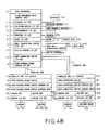
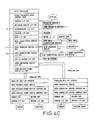
- FIG. 4A shows a postal teller machine system of this invention applying coins and Fig. 4B shows a system applying money card, while Fig. 4C shows a system applying both money card and coins.
- Fig. 4A shows a postal teller machine system of this invention applying coins
- Fig. 4B shows a system applying money card
- Fig. 4C shows a system applying both money card and coins.
- the system applying coins primarily includes a main processor 10, a display 720, a weighing device 500, a mail classifying device 160, a coin identifying device 170, a coin changing device 171, a printer 780, a key-in system 70, an automatic conveying device 30 and an automatic postage stamp device 25, wherein the main processor 10 includes a display I/F circuit 11, a weighing device I/F circuit 12, a mail classifying device I/F circuit 16, a coin changing device I/F circuit 17, coin identifying device I/F circuit 17A, a printer I/F CKT 14 commanding the printer 780 to work, a key-in system I/F CKT 18 capable of receiving commands from key- in system 70 and communicating therewith, on auto-conveying device I/F CKT 19 used to control auto-conveying device 30 and receive signals therefrom and communicate therewith, a parallel bus 22 related to the auto-conveying device I/F CKT 19, a parallel bus I/F CKT 22A, a postage stamp device I/
- the postage stamp device 25 includes a postage stamp device control SW 25A, a postage stamp device control unit 25B, a sensor CKT 25C, a sensor I/F CKT 25E, a sensor S5, S6, a driver CKT 25D, a driver I/F CKT 25F and a driver 251, 253, 256, etc.
- the auto-conveying device 30 includes an auto-conveying device control SW 30A, an auto-conveying device control unit 30B, a sensor CKT 30C, a sensor I/F CKT 30E, a sensor S1-S4, a driver CKT 30D, a driver I/F CKT 30F and a driver 300, wherein the auto-postage stamp device 25 transmits the signals obtained by sensors S5, S6 through the sensor I/F CKT 25E, sensor CKT 25C to auto-postage stamp device control unit 25B, auto-postage stamp device control SW 25A, and then the signals are converted into effective commands via the programs of the microprocessor and sent to the driver CKT 25D, driver I/F CKT 25F to command the drivers 251, 253, 256 to operate in accordance with the commands.
- While the auto-conveying device 30 also transmits the signals obtained by sensors S1-S4 through the sensor I/F CKT 30E, sensor CKT 30C to the auto-conveying device control unit 30B, auto-conveying device control SW 30A, and then the signals are converted into effective commands via the programs of the microprocessor and sent to the driver CKT 30D and driver I/F CKT 30F to command the driver 300 to operate according to the command.
- a modem 151 and a remote host 150 can be added to the above system, and a host I/F circuit 15 can be correspondingly added to the microprocessor so as to on line connect with general post office wirelessly or wiredly so that the general monitor center can control the operation state of the system.
- the money receiving device 172 can be replaced with a card reader/writer 711, and an asynchronous I/F circuit 13 can be correspondingly added to the microprocessor, as shown in Fig. 4B.
- the coin identifying device 170 and the relevant I/F circuit can be deleted.
- Fig. 4C a system applying both coins and money card is shown.
- the user can use coins or money card to pay the postage as desired.
- Fig. 4D it is identical to the system of Fig. 4C except a bar code printer 180 and bar code reading device 181 are added, and a bar code I/F circuit 18A is correspondingly added to the microprocessor.
- the user can put the ZIP code on the mail envelope read by the bar code reading device 181 and the bar code printer 180 will print the ZIP code on proper portion of the mail envelope, permitting the bar code identifying device to sort the mails according to their ZIP codes so that a great deal of labor and time are saved and the delivery speed is quickened.
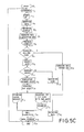
- FIGs. 5A through 5C wherein the operation of this invention is described in a flow chart manner.
- the system of this invention can be operated, one of which is the coin payment way (Fig. 5A), and the other of which is the money card payment way (Fig. 5B).
- the operation procedure of this invention starts from F1, and then goes to clearance F2, stand by F3, and dropping the mail into the mail drop 162 F4.
- the mail is carried to the weighing device 500 by the automatic conveying device 30 for weighing.
- the procedure then goes to F6.
- the mailer can see the weight of the mail from the display 720.
- the mailer presses one of the mail classifying keys 71 through 79 of the key-in system 70 according to the instruction of microprocessor.
- the microprocessor will according to the weight signal sent from the weighing device 500 and the sort of mail calculate the due postage and display the same on the display 720.
- the mailer In F9, if the mailer is not willing to send the mail, he/her can press the mail returning key 79, making the mail immediately returned, and in F91, F92 the mail will then be returned to the mail drop 162 by the automatic conveying device 30 in a reverse direction.
- the microprocessor will instruct the mailer on the display to insert the coins. The inserted coins are identified by money identifying device 170 and the amount of money will be displayed on the display.
- the mailer will be told if the amount is enough for paying the postage, and in case the mailer does not insert enough coins in a certain time, the mail will be returned, and the inserted coins will be returned by means of pressing the coin returning button 1721. The procedure then goes to F17 and ends. If excessive amount of coins are inserted, then the coin changing device 171 will return the change to the coin returning opening 1722. In F12, the display 720 will show the payment state, and the mail will be conveyed to the postal stamp device 25 for stamping. While the postage receipt will be released from the printer 780, and the procedure goes to F13 and F14.
- the stamped mail will be sent to the mail classifying device 160 from the rear side of the postal stamp device 25, and enter the mail storing box 161 as shown in Fig. 2.
- the payment data of the mail is then stored in the microprocessor and can be printed out by the printer if necessary.
- the procedure then goes to F15, F16 and F17 and ends.
- the procedure will go from F9 to F10A.
- the mailer can insert the money card into the money card insert slot 1720A as shown in Fig. 1.
- the card reader/writer (see Fig. 4B) will then judge if the money card is valid, and the procedure goes to F11A. If the money card is not valid, the procedure goes to F110 and F92 and the money card and mail are returned. In case the money card is valid, then the balance of the money card is shown by the display 720 in F11B. If the balance is judged to be enough for the postage, then the postage will be subtracted from the balance, and new balance is written in the money card.
- the procedure goes from F11C to F12A, F12B and F12C.
- the new balance is shown on the display 720 and the preceding F13, F14 and F15 repeat to return the money card.
- the procedure then goes from F15 to F15A, F16 and F17 and ends.
- F11C when paying the postage, it is found that the balance is insufficient to pay the postage, then the procedure goes to F110 as shown in Fig. 5A to return the mail.
- the mailer wants to use coins to pay the difference, he/her can press the hold-on key 1720B (see Fig. 1), and the procedure goes from F11D to F11E, i.e. the balance is totally subtracted and the money card is returned and the preceding steps repeat.
- the procedure goes from F11E to F11F, then to F10 (see Fig. 5A) or F10A and ends.
- FIG. 5C The flow chart of another embodiment of this invention is shown in Fig. 5C, wherein in F12, the display 720 displays the payment state, and in F121, the ZIP code shown on the mail envelope will be read by bar code reading device 181 (please refer to Figs. 1 and 4D). Therefore, the system will print out the receipt and the ZIP code and complete the stamping. The procedure goes from F13, F122 to F14, F15, F16 and F17 and ends.
- steps F121 and F122 can be added between steps F12C and F14 of Fig. 5B so that the system applying money card can also print ZIP code on the mail.
- the device 23 of the present invention comprises a conveying device 30 and a weighing scale 500, wherein the conveying device 30 includes a driving means 300, for example, a motor, a first conveying means 301B and a corresponding first idle wheel 201A thereof, a second conveying means 301C and a corresponding second idle wheel 201B, a fixed stand 400 (Fig.
- a movable stand 200 located under the movable stand 200, and a first sensor S1 located before the first conveying means 301B (see Fig. 7) and a second sensor S4 located after the second conveying means 301C.
- a novel aspect of the present invention is the movable stand 200 that includes a supporting stand with a rectangular opening 208 in the middle portion thereof. At both ends of th opening 208 there are disposed the first and second idle wheels 201A and 201B that are in cooperative relationship with the first and second conveying means 301B and 301C respectively to convey a standard mail L to be weighed.
- a movable end 122 of each of a pair of front and rear rocking arms 120 is pivotally connected at each end of the movable stand 200.
- the other end of each rocking arm 120 is pivotally connected at a pivot 101.
- a pair of electromagnetic actuators 100 such as a solenoid, is connected to the middle portion of the front rocking arm 120.
- the electromagnetic actuator 100 When the electromagnetic actuator 100 is activated, the movable end 122 is pulled down with the pivot 101 as a fulcrum. Since the moving stand 200 is attached to the movable ends 122 of both of the rocking arms 120, both movable ends 122 are actuated and descend simultaneously to move stand 200 to a lower horizontal plane.
- the first and second idle wheels 201A and 201B are connected to move with the movable stand 200 in vertical planes corresponding to the first and second conveying means 301B and 301C, respectively.
- the first conveying means 301B precedes the second conveying means 301C.
- the driving means 300 e.g. a stepping motor, drives the first, second conveying means.
- the first conveying means 301B is urged by a first pulley 302 (Fig. 6) and a first conveying belt 303 thereof.
- the first and second conveying means 301B, 301C are urged by second pulley 304, a second conveying belt 307 and third pulley 306.
- a weighing plate 501 of the weighing scale 500 is positioned above the main body of the weighing scale with its surface a little lower than the movable stand 200 so that the weighing plate 501 does not obstruct the conveyance of the article to be weighed.
- Figs. 6 through 7 Prior to reaching the first conveying means 301A and first idle wheel means 310, mail L comes in contact with the first sensor S1, such as photo-sensor, and the driving means 300 is actuated to convey mail L to a position to be weighed, as shown in Figs. 7 (initial position) and 5 (weighing position). In the positions shown in Fig. 4 and 5, the electromagnetic actuator 100 is not activated.
- the movable ends 122 of the rocking arms 120 due to the force of the springs 104, urge the first and second idle wheels 201A, 201B upward and in close contact with the first and second conveying means 301B, 301C, whereby the mail L can be delivered onto the movable stand 200 as shown in Fig. 7.
- the second sensor S2 When the mail L reaches the front edge of the second sensor S4 the second sensor S2 sends a sensor signal to actuator 100.
- the electromagnetic actuator 100 is thereby activated and the movable end 122 of the related rocking arm 120 is pulled down lowering movable stand 200 and the movable end of the other rocking arm.
- the mail L to be weighed is then seated on the weighing plate 501 of the weighing scale 500, as illustrated in Fig. 7.
- the weighing scale can weigh the mail L, and display the result on the display means 720 via microprocessor 10 or send out a signal to perform some other control functions.
- the electromagnetic actuator 100 will be deactivated, and both rocking arms 120 are drawn back by the force of the springs 104 and the movable stand 200 is restored to its initial positon.
- the mail L having been weighed, is again held between the first and second idle wheels 201A, 201B and the first and second conveying means 301B, 301C, and thus continues to be conveyed into the postage stamp device 25.
- the automatic weighing device 23 also includes an automatic conveying device 30 and a weighing scale 500, wherein the automatic conveying device 30 includes a driving means 300, a first conveying means 301B and a corresponding first idle wheel 201A, a second conveying means 301C and a corresponding second idle wheel 201B, and two belts 303, 304 which respectively drive the first and second conveying means.
- a fixed stand 400 is mounted on the weighing scale 500 for supporting the mail to be weighed
- a movable stand 200 is mounted on a main shaft 101 of the idle wheels 201A, 201B in a position slightly higher than the fixed stand 400 for the convenience of mail conveyance.
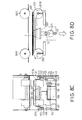
- An opening (not shown) is formed on central portion of the movable stand 200 above the weighing scale 500 so that when the movable stand 200 descends along with the idle wheels 201A, 201B, the fixed stand 400 mounted on the weighing scale 500 can go through the opening, permitting the movable stand 200 to smoothly descend, making the mail placed on the fixed stand 400 weighed under a condition wherein no other load exists (as shown in Fig.8D).
- Two ends of the main shaft 101 of the idle wheels 201A, 201B are respectively fixed to two side boards 104, 105.
- a screw rod 102 is disposed in parallel with inner face of the side board 104 with its one end extended through the main shaft 101 and its other end of fixed to a vertically telescopic guide rod 106.
- the guide rod 106 is further mounted on a journal 107.
- a cam shaft 108 is transversely disposed through the guide rod 106, a weighing scale base 109, a drive wheel 110 and a cam 111.
- Two follower wheels 112, 113 are disposed respectively above and below the cam 111.
- Two shafts 1121, 1131 of the follower wheels are fixed to two ends of a fixed support 114.
- a screw rod 103 is further disposed between the fixed support 114 and main shaft 101.
- Two springs 1031, 1021 are respectively disposed on the screw rods 103, 102 for holding the main shaft 101 in place.
- the follower wheels 112, 113 descend, making the fixed support 114 together with side board 105, main shaft 101 and idle wheel 201B desend.
- the guide rod 106 disposed at other end of the cam shaft 108 will be forced down into the journal 107 due to rotation of the cam shaft, making the other end of main shaft 101 and idle wheel 201A descend together to achieve balance of two end for weighing the mail (as shown in Figs. 8C and 8D).
- the drive wheel 110 will rotate clockwise or counterclockwise, making the idle wheels 201A, 201B and movable stand 200 return to their home positions.
- the driving means 300 will continuously operate to send the mail to next position for successive processing.
- the mail L is weighed during conveyance so that when the mail L goes into weighing position, the movable stand 200 is given a command to descend and temporarily separate from the automatic conveying device so that the mail L will be simply placed on the stand without touching other portion. After the weighing is completed, the separated stand 200 will return to its home position automatically for further conveying operation. The weight signal will be then input into microprocessor 10 through interface circuit 12 (see Fig. 1).
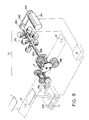
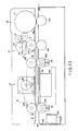
- the printer 25 includes a conveying system and a postmark printing system wherein the conveying system is arranged above and below a conveying reference surface A1, including a main driving means and first driving means, e.g., motor 251 of the conveying system, and a first roller 2512 driven through a timing belt 2510 (not shown).
- a main driving means and first driving means e.g., motor 251 of the conveying system
- a first roller 2512 driven through a timing belt 2510 (not shown).
- an idle roller 2514 with a stretching spring (not shown) above the first roller 2512.
- the postage stamp device 25 is shown in Figs.
- the postmark wheel means 271 further comprises a numeral wheel 2711, a gear 2712 attached therewith, a first rack 2713 engaged with the gear 2712, a guiding bar 2714 for the rack 2713 to move thereon, and a hooking arm 2715.
- the lower end of the hooking arm is secured to a recess 2506 of a second rack 2504.
- an encoder 234A and a main driver sensor 234 are disposed near the driving portion of the second stepper motor 256.
- an encoder 253A1 and a first wheel driver sensor 231 are disposed thereon.
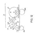
- the printing head 27 Prior to the entering of postal material into the conveying system, the printing head 27 is zeroed to its home position (not shown) wherein a motor 251 is the prime driving source of the conveying system. As shown in Fig. 12, disposed between the first roller 2512 and printing head 27 is a sensor S6 whereby after a postal material L passes through the sensor S6, the CPU 10 will actuate the printing head 27. Below the printing head 27 is a third idle wheel 2516 with stretching spring in order that the postal material L have a close contact with the numeral wheel 271 of the printing head 27, as shown in Fig. 12.
- the ink means 40 includes an ink tank 45, a first roller 44A, a second roller 47, a third roller 41 and an adjusting means 48.
- the ink means 40 pertains to prior art and the description thereof is therefore omitted herein.
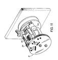
- the disclosure going thus far is made only with respect to a printing head with one numeral wheel, in practical operation, however, the device works with four numeral wheels or more than four numeral wheels arranged as two or more than two parallel sets, where in one set functions as date numeral wheel, the other as postal charge numeral wheel, as shown in Fig. 11.
- Various arrangement between a plurality of stepper motors 253A - 253F and their related second racks 2504A - 2504F for each set of character wheels can be arranged easily. As can be understood, more character wheels mentioned above can be arranged in accordance with the need.
- a relatively smaller diameter portion 2505B of the main shaft 2505 of the printing head is in alignment with that where the driving gear 253A4 is located, as shown in Fig. 10. It will be seen from the drawing, the outer perimeter of the relatively smaller diameter portion 2505B, just comes flush with the dented base 2502 of the second rack 2504, so that after respective stepper motors 253A - 253N are located at their proper positions and the main shaft 2505 of the printing head rotates, the second racks 2504 and the relatively smaller diamter portions 2505B can slip through the driving gear 253A4.
- the second rack 2504 for driving the character wheels of the printing head 27 can slide axially along the main shaft 2505, and also can rotate together with the main shaft 2505 after reaching its proper position, thus smoothing the work of the printing head 27 and reducing the very complicated machanism as needed in the cases of prior art work. This should also be concluded as one of the most important feature of this invention.
- the present invention essentially includes the automatic weighing device 23 and automatic postage stamp device 25, which have been described in preceding paragraph.
- a set of sensors S1 to S5 are provided whereby when a mail enters the system and is sensed by sensor S1, and the driver 300 consequently rotates to convey the mail forward, if sensor S2 senses the mail while sensor S3 does not to indicate a too short mail, then the driver 300 will reversely rotate to reject the mail. Moreover, when sensor S5 senses the mail while sensor S1 remains in sensing condition, a too long mail is indicated and the driver 300 also reversely rotates to reject the mail. Therefore, mails not meet length regulation will be removed in advance. This arrangement is a characteristic of the present invention.
Landscapes
- Physics & Mathematics (AREA)
- General Physics & Mathematics (AREA)
- Engineering & Computer Science (AREA)
- Mathematical Physics (AREA)
- Theoretical Computer Science (AREA)
- Devices For Checking Fares Or Tickets At Control Points (AREA)
- Financial Or Insurance-Related Operations Such As Payment And Settlement (AREA)
- Supports Or Holders For Household Use (AREA)
- Exchange Systems With Centralized Control (AREA)
- Lock And Its Accessories (AREA)
- Sheets, Magazines, And Separation Thereof (AREA)
- Sorting Of Articles (AREA)
- Management, Administration, Business Operations System, And Electronic Commerce (AREA)
- Devices For Dispensing Beverages (AREA)
- Beverage Vending Machines With Cups, And Gas Or Electricity Vending Machines (AREA)
Applications Claiming Priority (2)
| Application Number | Priority Date | Filing Date | Title |
|---|---|---|---|
| US07/536,496 US5313404A (en) | 1986-10-17 | 1990-06-11 | Automatic postal teller machine |
| US536496 | 1990-06-11 |
Publications (3)
| Publication Number | Publication Date |
|---|---|
| EP0462427A2 true EP0462427A2 (de) | 1991-12-27 |
| EP0462427A3 EP0462427A3 (en) | 1992-07-22 |
| EP0462427B1 EP0462427B1 (de) | 1995-12-06 |
Family
ID=24138738
Family Applications (1)
| Application Number | Title | Priority Date | Filing Date |
|---|---|---|---|
| EP91108694A Expired - Lifetime EP0462427B1 (de) | 1990-06-11 | 1991-05-28 | Automatischer Postschalter |
Country Status (13)
| Country | Link |
|---|---|
| US (1) | US5313404A (de) |
| EP (1) | EP0462427B1 (de) |
| CN (1) | CN1032277C (de) |
| AT (1) | ATE131301T1 (de) |
| AU (1) | AU7801991A (de) |
| BR (1) | BR9102379A (de) |
| CA (1) | CA2044235A1 (de) |
| DE (1) | DE69115132T2 (de) |
| ES (1) | ES2083480T3 (de) |
| IE (1) | IE911864A1 (de) |
| IL (1) | IL98302A0 (de) |
| PT (1) | PT97895A (de) |
| ZA (1) | ZA914222B (de) |
Cited By (10)
| Publication number | Priority date | Publication date | Assignee | Title |
|---|---|---|---|---|
| WO1994020933A1 (en) * | 1993-03-01 | 1994-09-15 | Halton System Oy | Method and device for the automated processing of parcels which are offered for dispatch |
| DE4406904A1 (de) * | 1994-03-03 | 1995-09-07 | Reinhold Maerz | Briefkasten mit einer selbsttätigen Stempeleinrichtung |
| EP0609092A3 (en) * | 1993-01-29 | 1996-04-17 | Neopost Ltd | Mail handling apparatus. |
| EP0880770A1 (de) | 1996-01-30 | 1998-12-02 | Nicholas Ernest Farren | Sicherheitssiegel |
| EP0864375A3 (de) * | 1997-02-28 | 2000-09-20 | Paolo Biagini | Automatischer Briefkasten |
| WO2000063849A1 (en) * | 1999-04-19 | 2000-10-26 | Pitney Bowes Inc. | Postage metering system having multiple currency capability |
| US6477514B1 (en) * | 1991-04-01 | 2002-11-05 | Pi Electronics Corp. | Automated self-service mail processing and storing systems |
| WO2007053047A1 (en) * | 2005-11-04 | 2007-05-10 | Piotr Baltruszewicz | Method and device automatically accepting documents, in particular paper or similar ones |
| WO2007088416A1 (en) * | 2006-02-03 | 2007-08-09 | Al Jenaibi Abdulla Hamad Saeed | Automatic registered mail service for the “automatic po box system” |
| WO2007088414A1 (en) * | 2006-02-03 | 2007-08-09 | Al Jenaibi Abdulla Hamad Saeed | Automatic mail sending machine for the automatic po box |
Families Citing this family (36)
| Publication number | Priority date | Publication date | Assignee | Title |
|---|---|---|---|---|
| US20020007281A1 (en) * | 1994-08-02 | 2002-01-17 | Asher Gil | Automated self-service mail processing and storing systems |
| US20040089482A1 (en) * | 1991-04-10 | 2004-05-13 | Uship Intellectual Properties, Llc | Automated package shipping machine |
| US5656799A (en) * | 1991-04-10 | 1997-08-12 | U-Ship, Inc. | Automated package shipping machine |
| US6917924B1 (en) | 1991-04-10 | 2005-07-12 | Uship Intellectual Properties, Llc | Automated package shipping machine |
| US5712787A (en) * | 1995-07-10 | 1998-01-27 | Canada Post Corporation | Electronic postal counter |
| ES2134006T3 (es) * | 1995-09-29 | 1999-09-16 | Siemens Nixdorf Inf Syst | Dispositivo y procedimiento para tratamiento de articulos postales. |
| US6178411B1 (en) | 1996-05-28 | 2001-01-23 | Joshua J. Reiter | Interactive process for applying or printing information on letters or parcels |
| US5819241A (en) * | 1996-05-28 | 1998-10-06 | Reiter; Joshua J. | Interactive process for applying or printing information on letters or parcels |
| US5737729A (en) * | 1996-06-04 | 1998-04-07 | Denman; Donald E. | Interactive kiosk for selecting and sending mail pieces |
| US5909373A (en) * | 1996-09-03 | 1999-06-01 | Pitney Bowes Inc. | System for discounting postage for a postage kiosk containing a franking machine |
| US5826246A (en) * | 1996-12-31 | 1998-10-20 | Pitney Bowes Inc. | Secure postage meter in an ATM application |
| AU5152599A (en) * | 1998-06-08 | 1999-12-30 | Friendlyway Aktiengesellschaft Fur Anwenderfreundliche Systeme | Mail handling device |
| KR20010072111A (ko) | 1998-07-31 | 2001-07-31 | 추후제출 | 우편물수속시스템 |
| ES2164571B1 (es) * | 1999-11-24 | 2003-05-16 | Sanchez Pedro Palomo | Maquina expendedora de sellos y franqueadora de sobres. |
| AU3002501A (en) * | 2000-02-07 | 2001-08-20 | Crisplant A/S | A parcel self-servicing machine |
| US20010042055A1 (en) * | 2000-02-07 | 2001-11-15 | Jan Didriksen | Parcel self-servicing machine |
| WO2002001521A1 (fr) * | 2000-06-28 | 2002-01-03 | G. Holdings Ltd. | Système de transaction avec dispositif personnel portatif d'identification et de contrôle de transaction |
| IT1319399B1 (it) * | 2000-07-26 | 2003-10-10 | Consultbank Dott Giovanni Long | Apparecchiatura e metodo per l'accettazione ed il processamentoautomatico di plichi postali. |
| EP1371036A2 (de) * | 2001-03-16 | 2003-12-17 | G. Holdings Ltd | Verfahren und system für erneuerung von identifikationsdaten in einer tragbaren transaktionseinrichtung |
| WO2003039307A1 (en) * | 2001-11-02 | 2003-05-15 | Rudy Simon | Safety apparatus and method for automated services |
| AU2002364512A1 (en) * | 2001-11-29 | 2003-06-10 | Lockheed Martin Corporation | Apparatus for testing for particulate contaminants in depositories for mail-like articles |
| US20030217018A1 (en) * | 2002-05-17 | 2003-11-20 | Groff Jason J. | System and method for conducting a shipping transaction |
| US6745933B2 (en) * | 2002-06-05 | 2004-06-08 | Robin G. Liphard | Method for providing a pre-security depository |
| CN1484197B (zh) * | 2002-09-19 | 2012-10-03 | 陆洪瑞 | 一种智能批量付款装置 |
| SE0300585L (sv) * | 2003-03-04 | 2004-09-05 | Anna Karin Saetherblom | Brevlåda |
| EP1687143A4 (de) * | 2003-10-15 | 2008-06-18 | Marvin Blumberg | System und verfahren zur bereitstellung von zustellnachweis |
| US20050108111A1 (en) * | 2003-11-17 | 2005-05-19 | Kranyec Stephen L. | Mailing kiosk with safeguards and methods of use |
| WO2007133675A2 (en) * | 2006-05-11 | 2007-11-22 | Loadstar Sensors, Inc. | Capacitive force-measuring device based load sensing platform |
| CN101211468B (zh) * | 2006-12-29 | 2011-02-02 | 浙江工业大学 | 机械戳式邮资机 |
| DE102008062002A1 (de) * | 2008-12-12 | 2010-06-17 | Francotyp-Postalia Gmbh | Einrichtung und Verfahren zur Poststückannahme |
| US9478094B2 (en) | 2009-12-29 | 2016-10-25 | Pitney Bowes Inc. | Postal services kiosk having payment card security |
| KR20130118143A (ko) | 2012-04-19 | 2013-10-29 | 한국전자통신연구원 | 우편물의 자동 정렬이 가능한 적재 제어장치 |
| CN103337101A (zh) * | 2013-05-29 | 2013-10-02 | 郑红光 | 信件自动收取装置 |
| CN104331940B (zh) * | 2014-11-26 | 2017-03-15 | 天津慧科电子股份有限公司 | 一种高效密集投送的智能邮递终端 |
| CN104687990A (zh) * | 2015-03-12 | 2015-06-10 | 上海理工大学 | 高效率收发信件的装置 |
| CN107472902B (zh) * | 2017-07-07 | 2019-05-17 | 长兴技师学院 | 一种餐盘回收监督机 |
Family Cites Families (17)
| Publication number | Priority date | Publication date | Assignee | Title |
|---|---|---|---|---|
| US3290491A (en) * | 1961-06-19 | 1966-12-06 | Eric C Wahlberg | Automatic mailing machine |
| US3613808A (en) * | 1968-12-18 | 1971-10-19 | Fmc Corp | Article-sorting apparatus with transfer-error-reducing arrangement |
| US4024380A (en) * | 1971-01-18 | 1977-05-17 | Damon Mott Gunn | Self service postal apparatus and method |
| JPS5246930A (en) * | 1975-10-11 | 1977-04-14 | Alps Electric Co Ltd | Type selector |
| US4319328A (en) * | 1980-02-27 | 1982-03-09 | Sabre Products, Inc. | Postage cost recording system |
| US4495581A (en) * | 1981-10-19 | 1985-01-22 | Piccione James M | User programmable postal rate calculator |
| US4488610A (en) * | 1982-05-17 | 1984-12-18 | Data-Pac Mailing Systems Corp. | Sorting apparatus |
| US4579213A (en) * | 1982-09-30 | 1986-04-01 | Drewry Photocolor Corporation | Apparatus for an automated vending machine for arbitrarily priced articles |
| US4595984A (en) * | 1982-10-22 | 1986-06-17 | Pitney Bowes Inc. | Apparatus and method for determining special postage fees |
| US4516209A (en) * | 1983-02-09 | 1985-05-07 | Pitney Bowes Inc. | Postage metering system having weight checking capability |
| US4584648A (en) * | 1983-09-14 | 1986-04-22 | Pitney Bowes Inc. | Post office window system with programmable prompts |
| AU599336B2 (en) * | 1986-10-17 | 1990-07-19 | Wu Sheng-Jung | Microcomputerized automatic post counter |
| FR2610403B1 (fr) * | 1987-01-30 | 1991-06-14 | Jet Services | Systeme et procede de pesee d'un objet, avec edition automatique d'une etiquette |
| US4900905A (en) * | 1988-08-01 | 1990-02-13 | Pavo Pusic | Automated mail collecting and telecommunication machine |
| US5025386A (en) * | 1988-08-01 | 1991-06-18 | Pavo Pusic | Automated mail collecting and telecommunication machine II |
| US5065000A (en) * | 1988-08-01 | 1991-11-12 | Pavo Pusic | Automated electronic postage meter having a direct acess bar code printer |
| US4923022B1 (en) * | 1989-04-25 | 1994-04-12 | Hsieh Tzu Yen | Automatic mailing apparatus |
-
1990
- 1990-06-11 US US07/536,496 patent/US5313404A/en not_active Expired - Fee Related
-
1991
- 1991-05-28 EP EP91108694A patent/EP0462427B1/de not_active Expired - Lifetime
- 1991-05-28 ES ES91108694T patent/ES2083480T3/es not_active Expired - Lifetime
- 1991-05-28 AT AT91108694T patent/ATE131301T1/de not_active IP Right Cessation
- 1991-05-28 DE DE69115132T patent/DE69115132T2/de not_active Expired - Fee Related
- 1991-05-29 IL IL98302A patent/IL98302A0/xx unknown
- 1991-05-30 AU AU78019/91A patent/AU7801991A/en not_active Abandoned
- 1991-05-31 IE IE186491A patent/IE911864A1/en unknown
- 1991-06-04 ZA ZA914222A patent/ZA914222B/xx unknown
- 1991-06-07 BR BR919102379A patent/BR9102379A/pt not_active Application Discontinuation
- 1991-06-07 PT PT97895A patent/PT97895A/pt not_active Application Discontinuation
- 1991-06-08 CN CN91103980A patent/CN1032277C/zh not_active Expired - Fee Related
- 1991-06-10 CA CA002044235A patent/CA2044235A1/en not_active Abandoned
Cited By (12)
| Publication number | Priority date | Publication date | Assignee | Title |
|---|---|---|---|---|
| US6477514B1 (en) * | 1991-04-01 | 2002-11-05 | Pi Electronics Corp. | Automated self-service mail processing and storing systems |
| EP0609092A3 (en) * | 1993-01-29 | 1996-04-17 | Neopost Ltd | Mail handling apparatus. |
| WO1994020933A1 (en) * | 1993-03-01 | 1994-09-15 | Halton System Oy | Method and device for the automated processing of parcels which are offered for dispatch |
| NL9300378A (nl) * | 1993-03-01 | 1994-10-03 | Halton System Oy | Werkwijze en inrichting voor het geautomatiseerd verwerken van ter verzending aangeboden pakketten. |
| DE4406904A1 (de) * | 1994-03-03 | 1995-09-07 | Reinhold Maerz | Briefkasten mit einer selbsttätigen Stempeleinrichtung |
| EP0880770A1 (de) | 1996-01-30 | 1998-12-02 | Nicholas Ernest Farren | Sicherheitssiegel |
| EP0864375A3 (de) * | 1997-02-28 | 2000-09-20 | Paolo Biagini | Automatischer Briefkasten |
| WO2000063849A1 (en) * | 1999-04-19 | 2000-10-26 | Pitney Bowes Inc. | Postage metering system having multiple currency capability |
| US6178412B1 (en) * | 1999-04-19 | 2001-01-23 | Pitney Bowes Inc. | Postage metering system having separable modules with multiple currency capability and synchronization |
| WO2007053047A1 (en) * | 2005-11-04 | 2007-05-10 | Piotr Baltruszewicz | Method and device automatically accepting documents, in particular paper or similar ones |
| WO2007088416A1 (en) * | 2006-02-03 | 2007-08-09 | Al Jenaibi Abdulla Hamad Saeed | Automatic registered mail service for the “automatic po box system” |
| WO2007088414A1 (en) * | 2006-02-03 | 2007-08-09 | Al Jenaibi Abdulla Hamad Saeed | Automatic mail sending machine for the automatic po box |
Also Published As
| Publication number | Publication date |
|---|---|
| ES2083480T3 (es) | 1996-04-16 |
| ZA914222B (en) | 1992-03-25 |
| DE69115132D1 (de) | 1996-01-18 |
| IL98302A0 (en) | 1992-06-21 |
| IE911864A1 (en) | 1991-12-18 |
| CA2044235A1 (en) | 1991-12-12 |
| EP0462427A3 (en) | 1992-07-22 |
| BR9102379A (pt) | 1992-01-14 |
| US5313404A (en) | 1994-05-17 |
| CN1057349A (zh) | 1991-12-25 |
| AU7801991A (en) | 1991-12-12 |
| CN1032277C (zh) | 1996-07-10 |
| EP0462427B1 (de) | 1995-12-06 |
| ATE131301T1 (de) | 1995-12-15 |
| PT97895A (pt) | 1993-08-31 |
| DE69115132T2 (de) | 1996-05-09 |
Similar Documents
| Publication | Publication Date | Title |
|---|---|---|
| EP0462427B1 (de) | Automatischer Postschalter | |
| US5272640A (en) | Automatic mail-processing device with full functions | |
| EP0264502B1 (de) | Automatische Postbehandlungsvorrichtung | |
| US4733359A (en) | Document collating and inserting system having displays for document count verification | |
| WO1990001742A1 (en) | Automated mail collecting and telecommunication machine | |
| EP0426755A1 (de) | Selbsttätiger elektronischer Postgebührenzähler mit zwei Wägeflächen | |
| CA2019956C (en) | Method & apparatus for printing postal code markings | |
| EP0396298B1 (de) | Digitaler Zeichendrucker | |
| US5225665A (en) | Ticket originating and processing device for transit vehicle | |
| GB2166389A (en) | Electronic postage meter print wheel setting optimization system | |
| US20040089706A1 (en) | Card package production system having multidirectinal card package distribution module with stacker and reject gate and method | |
| US8297860B2 (en) | System and method for improving print quality on mail pieces having low reflectivity | |
| CA2049407A1 (en) | Automatic mail-processing device with full functions | |
| US7186040B2 (en) | Arrangement for generation of a print image for franking and postmarking machines | |
| JPH05101238A (ja) | 全自動ポスト・カウンター | |
| GB2235656A (en) | Postage meter with automatic feed of mailpieces from weighscale | |
| CA2111134A1 (en) | Mailing machine including improved tape dispensing means and control system therefor | |
| US4745346A (en) | Electronic postage meter print wheel setting optimization system | |
| CA1255003A (en) | Electronic postage meter print wheel setting optimization system | |
| EP1178440A1 (de) | Vorrichtung und Methode zur automatischen Annahme von Postgut | |
| CA2406509A1 (en) | Card package production system with adhesive card attachment station and method | |
| CA1283979C (en) | Microcomputerized automatic post counter | |
| JPH0751647Y2 (ja) | カ−ド発売装置 | |
| US20030209303A1 (en) | Card package production system with card reversing card attachment station and method | |
| KR930000168A (ko) | 전자동 포스트 카운터 |
Legal Events
| Date | Code | Title | Description |
|---|---|---|---|
| PUAI | Public reference made under article 153(3) epc to a published international application that has entered the european phase |
Free format text: ORIGINAL CODE: 0009012 |
|
| AK | Designated contracting states |
Kind code of ref document: A2 Designated state(s): AT BE CH DE DK ES FR GB IT LI NL SE |
|
| PUAL | Search report despatched |
Free format text: ORIGINAL CODE: 0009013 |
|
| AK | Designated contracting states |
Kind code of ref document: A3 Designated state(s): AT BE CH DE DK ES FR GB IT LI NL SE |
|
| 17P | Request for examination filed |
Effective date: 19930112 |
|
| 17Q | First examination report despatched |
Effective date: 19940118 |
|
| GRAA | (expected) grant |
Free format text: ORIGINAL CODE: 0009210 |
|
| AK | Designated contracting states |
Kind code of ref document: B1 Designated state(s): AT BE CH DE DK ES FR GB IT LI NL SE |
|
| PG25 | Lapsed in a contracting state [announced via postgrant information from national office to epo] |
Ref country code: NL Free format text: LAPSE BECAUSE OF FAILURE TO SUBMIT A TRANSLATION OF THE DESCRIPTION OR TO PAY THE FEE WITHIN THE PRESCRIBED TIME-LIMIT Effective date: 19951206 Ref country code: DK Effective date: 19951206 Ref country code: BE Effective date: 19951206 Ref country code: AT Effective date: 19951206 |
|
| REF | Corresponds to: |
Ref document number: 131301 Country of ref document: AT Date of ref document: 19951215 Kind code of ref document: T |
|
| REF | Corresponds to: |
Ref document number: 69115132 Country of ref document: DE Date of ref document: 19960118 |
|
| ITF | It: translation for a ep patent filed | ||
| PG25 | Lapsed in a contracting state [announced via postgrant information from national office to epo] |
Ref country code: SE Effective date: 19960306 |
|
| ET | Fr: translation filed | ||
| REG | Reference to a national code |
Ref country code: ES Ref legal event code: FG2A Ref document number: 2083480 Country of ref document: ES Kind code of ref document: T3 |
|
| REG | Reference to a national code |
Ref country code: CH Ref legal event code: NV Representative=s name: BUECHEL, VON REVY & PARTNER |
|
| NLV1 | Nl: lapsed or annulled due to failure to fulfill the requirements of art. 29p and 29m of the patents act | ||
| PG25 | Lapsed in a contracting state [announced via postgrant information from national office to epo] |
Ref country code: LI Effective date: 19960531 Ref country code: CH Effective date: 19960531 |
|
| PLBE | No opposition filed within time limit |
Free format text: ORIGINAL CODE: 0009261 |
|
| STAA | Information on the status of an ep patent application or granted ep patent |
Free format text: STATUS: NO OPPOSITION FILED WITHIN TIME LIMIT |
|
| 26N | No opposition filed | ||
| REG | Reference to a national code |
Ref country code: CH Ref legal event code: PL |
|
| PGFP | Annual fee paid to national office [announced via postgrant information from national office to epo] |
Ref country code: ES Payment date: 20010629 Year of fee payment: 11 |
|
| REG | Reference to a national code |
Ref country code: GB Ref legal event code: IF02 |
|
| PG25 | Lapsed in a contracting state [announced via postgrant information from national office to epo] |
Ref country code: ES Free format text: LAPSE BECAUSE OF NON-PAYMENT OF DUE FEES Effective date: 20020529 |
|
| REG | Reference to a national code |
Ref country code: ES Ref legal event code: FD2A Effective date: 20030611 |
|
| PGFP | Annual fee paid to national office [announced via postgrant information from national office to epo] |
Ref country code: GB Payment date: 20040528 Year of fee payment: 14 |
|
| PGFP | Annual fee paid to national office [announced via postgrant information from national office to epo] |
Ref country code: FR Payment date: 20040601 Year of fee payment: 14 |
|
| PGFP | Annual fee paid to national office [announced via postgrant information from national office to epo] |
Ref country code: DE Payment date: 20040721 Year of fee payment: 14 |
|
| PG25 | Lapsed in a contracting state [announced via postgrant information from national office to epo] |
Ref country code: IT Free format text: LAPSE BECAUSE OF NON-PAYMENT OF DUE FEES;WARNING: LAPSES OF ITALIAN PATENTS WITH EFFECTIVE DATE BEFORE 2007 MAY HAVE OCCURRED AT ANY TIME BEFORE 2007. THE CORRECT EFFECTIVE DATE MAY BE DIFFERENT FROM THE ONE RECORDED. Effective date: 20050528 Ref country code: GB Free format text: LAPSE BECAUSE OF NON-PAYMENT OF DUE FEES Effective date: 20050528 |
|
| PG25 | Lapsed in a contracting state [announced via postgrant information from national office to epo] |
Ref country code: DE Free format text: LAPSE BECAUSE OF NON-PAYMENT OF DUE FEES Effective date: 20051201 |
|
| GBPC | Gb: european patent ceased through non-payment of renewal fee |
Effective date: 20050528 |
|
| PG25 | Lapsed in a contracting state [announced via postgrant information from national office to epo] |
Ref country code: FR Free format text: LAPSE BECAUSE OF NON-PAYMENT OF DUE FEES Effective date: 20060131 |
|
| REG | Reference to a national code |
Ref country code: FR Ref legal event code: ST Effective date: 20060131 |