EP0463443A2 - Dispositif pour positionner de bobines mises sur des supports individuels indépendants et qui provoque la rotation autour leur axe vertical - Google Patents
Dispositif pour positionner de bobines mises sur des supports individuels indépendants et qui provoque la rotation autour leur axe vertical Download PDFInfo
- Publication number
- EP0463443A2 EP0463443A2 EP91109438A EP91109438A EP0463443A2 EP 0463443 A2 EP0463443 A2 EP 0463443A2 EP 91109438 A EP91109438 A EP 91109438A EP 91109438 A EP91109438 A EP 91109438A EP 0463443 A2 EP0463443 A2 EP 0463443A2
- Authority
- EP
- European Patent Office
- Prior art keywords
- rollers
- roller
- individual carriers
- transport path
- individual
- Prior art date
- Legal status (The legal status is an assumption and is not a legal conclusion. Google has not performed a legal analysis and makes no representation as to the accuracy of the status listed.)
- Granted
Links
- 239000000969 carrier Substances 0.000 title claims abstract description 43
- 230000005291 magnetic effect Effects 0.000 claims abstract description 37
- XEEYBQQBJWHFJM-UHFFFAOYSA-N Iron Chemical group [Fe] XEEYBQQBJWHFJM-UHFFFAOYSA-N 0.000 claims abstract description 13
- 238000011144 upstream manufacturing Methods 0.000 claims abstract description 8
- 239000003302 ferromagnetic material Substances 0.000 claims abstract 2
- 230000004907 flux Effects 0.000 claims description 4
- 239000000696 magnetic material Substances 0.000 claims description 3
- 230000005540 biological transmission Effects 0.000 abstract description 3
- 230000032258 transport Effects 0.000 description 43
- 238000002360 preparation method Methods 0.000 description 15
- 230000000694 effects Effects 0.000 description 3
- 238000004804 winding Methods 0.000 description 3
- 230000015572 biosynthetic process Effects 0.000 description 2
- 238000005096 rolling process Methods 0.000 description 2
- 230000009471 action Effects 0.000 description 1
- 230000004888 barrier function Effects 0.000 description 1
- 230000008901 benefit Effects 0.000 description 1
- 238000001514 detection method Methods 0.000 description 1
- 238000003754 machining Methods 0.000 description 1
- 238000000034 method Methods 0.000 description 1
- 230000035515 penetration Effects 0.000 description 1
- 238000003825 pressing Methods 0.000 description 1
- 230000008569 process Effects 0.000 description 1
- 230000004044 response Effects 0.000 description 1
- 238000009987 spinning Methods 0.000 description 1
- 238000003860 storage Methods 0.000 description 1
- 230000007704 transition Effects 0.000 description 1
- 230000001960 triggered effect Effects 0.000 description 1
Images




Classifications
-
- B—PERFORMING OPERATIONS; TRANSPORTING
- B65—CONVEYING; PACKING; STORING; HANDLING THIN OR FILAMENTARY MATERIAL
- B65H—HANDLING THIN OR FILAMENTARY MATERIAL, e.g. SHEETS, WEBS, CABLES
- B65H67/00—Replacing or removing cores, receptacles, or completed packages at paying-out, winding, or depositing stations
- B65H67/08—Automatic end-finding and material-interconnecting arrangements
- B65H67/086—Preparing supply packages
-
- B—PERFORMING OPERATIONS; TRANSPORTING
- B65—CONVEYING; PACKING; STORING; HANDLING THIN OR FILAMENTARY MATERIAL
- B65H—HANDLING THIN OR FILAMENTARY MATERIAL, e.g. SHEETS, WEBS, CABLES
- B65H2701/00—Handled material; Storage means
- B65H2701/30—Handled filamentary material
- B65H2701/31—Textiles threads or artificial strands of filaments
Definitions
- the invention relates to a device according to the features of the preamble of the first claim.
- DE-OS 32 35 442 describes a device in which the individual carrier is positioned by holding elements and prevented from rotating.
- a driven friction wheel swivels to the cop base and rotates the cop on the mandrel of the single carrier. Any existing foot turns clamped by the friction wheel, which means that they cannot be released. In order to avoid that the friction wheel comes into contact with the main winding of the cop, it must be very narrow and precisely positionable.
- the guide rail 3 has a cutout 15 in the area of the positioning and rotating device according to the invention.
- the opposite guide rail 3 ' has curvatures in this area which are adapted to the transport path of the individual carriers 4 when they roll around rollers 10 and 11.
- the individual carriers 4 have the traditional shape with base plate 5, base 7 and arbor 7 'for the cop 8. However, the base 7 can also be dispensed with if the guide rails guide the individual carriers 4 only on their base plates 5.
- the central control unit 14 can receive a signal from a bobbin preparation device, not shown, which is converted into corresponding control commands. This can be, for example, the reversal of the direction of rotation of the motors 12 and 13 in order to be able, for example, to wind up a thread end found on the tip of the head.
- the central control unit 14 and a control line 10 'can also be used for the roller 10 Solenoid 17 are switched off. As a result, the roller 10 then no longer exerts a magnetic force on the iron ring 6 of the individual carrier 4.
- FIG. 4 shows a transport track section analogous to FIG. 1.
- Rollers 39 and 40 which consist of permanent magnets, are mounted in a common support plate 41.
- This support plate 41 can be moved horizontally by means of a hydraulic cylinder 44.
- the support plate 41 is connected to the hydraulic cylinder 44 via a plunger 44 ′′.
- a motor 42 is also attached to the support plate and can drive the rollers 39 and 40 individually or together via a gear 43.
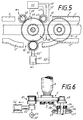
- roller 47 can be configured analogously to the roller 10 or 22, the roller 48 does not generate any magnetic force on the individual carrier 4 '.
- the upstream roller 47 initially has the main function of catching the incoming individual carrier 4 '. This single carrier then rolls around the roller 47 against the roller 48. Its arrival is detected by a sensor 49, which reports this to a central control unit 50 via a signal line 49 '.
- This central control unit 50 is connected via a control line 52 'to a hydraulic cylinder 52 which positions the roller 51 via a plunger 52' '. This roller 51 is therefore only moved into the transport path 1 when the individual carrier 4 'has reached the preparation position.
- the roller 48 like the roller 51, is adapted to the different shape of the base plate 5 'of the single carrier 4'.
- the roller 47 not shown in section here, also has the same shape.
- Such individual carriers 4 ' have the advantage that they can easily overcome unevenness in the transport system.
- the roller 48 is mounted with its shaft 48 'in a ball bearing 54.
- the ball bearing 54 is fastened in a holder 55, which in turn is connected to the machine frame 57 by means of fastening screws 56 and 58.
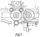
- the sensor 83 is connected to a central control unit 82 via a line 83 '. It is attached to the base 7 of the individual carrier 4. This can be a photo sensor, which is connected to a reflector (not shown) attached to the opposite side of the transport path 70.
- a single carrier 4 is rolled by the magnetic force action of the roller 77 on its iron ring 6 from the conveyor belt 72 onto the slideways 75 and 76 (position a). This rolling movement is supported both by the conveyor belt 72 and by the drive of the roller 77 in the direction indicated.
- the slide rails 75 and 76 like the slide rails 84 and 85, are formed in a C-shape on the transport tracks 70 and 71, as has already been described in the previous exemplary embodiments.
- the individual carrier 4 which is conveyed by the transport track 70 onto the slide rails 75 and 76, then arrives in a position b shown in dash-dotted lines between the two rollers 77 and 78.
- the magnet coil associated with the roller 78 is also activated.
- the rollers 77 and 78 transmit the rotational movement required for preparing the cops to the individual carrier 4.
- the rollers 77 and 78 receive their drive from motors 79 and 80, which are controlled by the central control unit 82 via control lines 79 'and 80'.
- a stopper in the transport path 70 was dispensed with. If a single carrier 4 is arranged in the cop preparation position between the rollers 77 and 78 and is held by the magnetic force emanating from the rollers 77 and 78, an individual carrier 4 transported past on the conveyor belt 72 rolls on the circumferential surface of the base plate of this single carrier and is thereby on the Preparation station passed. This makes it possible to automatically distribute the individual carriers 4 with attached cops 8 to these preparation stations when a plurality of cop preparation stations are arranged between the transport tracks 70 and 71.
- a sensor 87 is arranged here between the rollers 77 and 78, which detects the exit of a single carrier 4 from the preparation station and thus the entry into the transport path 71 and reports it to the central control unit 82 via a signal line 87 '.
- the central control unit switches the solenoid of the roller 77 on again via the control line 77 ′ in order to catch the next individual carrier 4 and to feed it to the treatment station.
- the two rollers arranged one behind the other in the direction of transport exert a magnetic force on the individual carriers 4, it is particularly advantageous to provide a different polarity, as a result of which the part of the iron core 6 of the individual carrier 4 lying between the two rollers forms a bridge for forms the magnetic flux lines, whereby the magnetic force effect increases significantly.
Landscapes
- Rollers For Roller Conveyors For Transfer (AREA)
- Replacing, Conveying, And Pick-Finding For Filamentary Materials (AREA)
Applications Claiming Priority (2)
| Application Number | Priority Date | Filing Date | Title |
|---|---|---|---|
| DE4019099A DE4019099A1 (de) | 1990-06-15 | 1990-06-15 | Vorrichtung zum positionieren von auf unabhaengige einzeltraeger aufgesetzten spulen und drehen um deren laengsachse |
| DE4019099 | 1990-06-15 |
Publications (3)
| Publication Number | Publication Date |
|---|---|
| EP0463443A2 true EP0463443A2 (fr) | 1992-01-02 |
| EP0463443A3 EP0463443A3 (en) | 1992-01-22 |
| EP0463443B1 EP0463443B1 (fr) | 1994-11-30 |
Family
ID=6408434
Family Applications (1)
| Application Number | Title | Priority Date | Filing Date |
|---|---|---|---|
| EP91109438A Expired - Lifetime EP0463443B1 (fr) | 1990-06-15 | 1991-06-08 | Dispositif pour positionner de bobines mises sur des supports individuels indépendants et qui provoque la rotation autour leur axe vertical |
Country Status (3)
| Country | Link |
|---|---|
| US (1) | US5127509A (fr) |
| EP (1) | EP0463443B1 (fr) |
| DE (2) | DE4019099A1 (fr) |
Families Citing this family (18)
| Publication number | Priority date | Publication date | Assignee | Title |
|---|---|---|---|---|
| DE4011797C2 (de) * | 1989-06-10 | 1998-02-12 | Schlafhorst & Co W | Transportsystem für eine automatische Textilmaschine zum gesteuerten Führen von Paletten entlang vorgegebener Transportwege |
| IT1272872B (it) * | 1995-01-10 | 1997-07-01 | Savio Macchine Tessili Srl | Dispositivo per il posizionamento controllato delle spole in una stazione di una roccatrice automatica |
| JP2899535B2 (ja) * | 1995-02-20 | 1999-06-02 | 照明 伊藤 | 検体容器ホルダーおよびホルダー搬送装置 |
| EP0870614B1 (fr) * | 1997-04-11 | 2001-10-04 | Thyssen Krupp Stahl AG | Rouleau revêtu avec identification durable et méthode pour la réalisation d'identification |
| DE19816232A1 (de) * | 1998-04-10 | 1999-10-14 | Schlafhorst & Co W | Transportsystem für Spinnspulen und Spulenhülsen mit einem einen Durchgang überbrückenden Transportweg |
| JP3839441B2 (ja) * | 2004-03-22 | 2006-11-01 | 株式会社アイディエス | 試験管搬送路の搬送方向変換装置 |
| JP4666970B2 (ja) * | 2004-07-28 | 2011-04-06 | キヤノン株式会社 | 搬送装置及び該装置を備えた記録装置 |
| US8037993B2 (en) * | 2006-12-04 | 2011-10-18 | Inpeco Ip Ltd. | Container carrier turning device for a container carrier conveyor |
| DE102008017256A1 (de) * | 2008-04-04 | 2009-10-08 | Oerlikon Textile Gmbh & Co. Kg | Vorbereitungseinrichtung für Spinnkopse |
| FR2948926B1 (fr) * | 2009-08-06 | 2011-10-21 | Michelin Soc Tech | Transitique adaptee au transfert et au stockage des carcasses de pneumatiques |
| US9352913B2 (en) * | 2013-03-14 | 2016-05-31 | Sealy Technology, Llc | Innerspring manufacturing and assembly system and components for selectable coil orientation, position adjustment and coil conveyance |
| US11076705B2 (en) | 2014-05-30 | 2021-08-03 | Sealy Technology, Llc | Spring core with integrated cushioning layer |
| WO2017081279A1 (fr) * | 2015-11-12 | 2017-05-18 | Roche Diagnostics Gmbh | Dispositif de manipulation d'échantillon et procédé de manipulation d'échantillon |
| ES2977948T3 (es) | 2015-12-17 | 2024-09-03 | Sealy Technology Llc | Resorte helicoidal en espiral con respuesta de carga variable y colchones que incluyen el mismo |
| PL3841921T3 (pl) | 2016-01-21 | 2025-03-24 | Sealy Technology, Llc | Sprężyny typu coil-in-coil z nieliniowymi reakcjami na obciążenie i materace zawierające takie sprężyny |
| US10598242B2 (en) | 2016-05-20 | 2020-03-24 | Sealy Technology, Llc | Coil springs with non-linear loading responses and mattresses including the same |
| DE102016013486B3 (de) * | 2016-11-11 | 2018-01-04 | Admedes Schuessler Gmbh | Flechtmaschine und Weiche für eine Flechtmaschine |
| WO2019089429A1 (fr) | 2017-10-31 | 2019-05-09 | Sealy Technology, Llc | Ensemble ressort hélicoïdal ensaché comprenant une mousse souple |
Family Cites Families (18)
| Publication number | Priority date | Publication date | Assignee | Title |
|---|---|---|---|---|
| DE7301717U (de) * | 1973-01-18 | 1973-05-10 | Licentia Gmbh | Kopsbehälter |
| US3901381A (en) * | 1973-10-10 | 1975-08-26 | Ball Brothers Service Corp | Automatic ware handler |
| CH570912A5 (fr) * | 1974-03-11 | 1975-12-31 | Emhart Zuerich Sa | |
| US3993199A (en) * | 1975-05-05 | 1976-11-23 | Velasco Scale Company, Inc. | Filler-fitting alignment apparatus |
| JPS5225139A (en) * | 1975-08-18 | 1977-02-24 | Kanebo Ltd | Method of conveying bobbins of textile machine |
| US4081072A (en) * | 1976-04-02 | 1978-03-28 | Possis Corporation | Automatic conveyor system for moving articles successively to a series of work stations |
| US4257151A (en) * | 1979-03-23 | 1981-03-24 | The Coca-Cola Company | Inspection station for beverage containers |
| JPS5859167A (ja) * | 1981-09-25 | 1983-04-08 | Murata Mach Ltd | 管糸搬送システム |
| JPS5969368A (ja) * | 1982-10-12 | 1984-04-19 | Murata Mach Ltd | ボビン搬送システム |
| US4681231A (en) * | 1982-12-08 | 1987-07-21 | Murata Kikai Kabushiki Kaisha | Article selecting and conveying system |
| JPS61169452A (ja) * | 1985-01-23 | 1986-07-31 | Murata Mach Ltd | 糸端の口出し装置 |
| JPS6270178A (ja) * | 1985-09-24 | 1987-03-31 | Murata Mach Ltd | 糸端の口出し装置 |
| DE3586248T2 (de) * | 1985-10-15 | 1993-01-28 | Murata Machinery Ltd | Fuehrungsanordnung fuer garnenden. |
| US4842206A (en) * | 1987-12-21 | 1989-06-27 | Murata Kikai Kabushiki Kaisha | Automatic yarn end finding device for a spinning bobbin |
| DE3912488A1 (de) * | 1989-04-15 | 1990-10-18 | Schlafhorst & Co W | Verfahren und vorrichtung zur uebermittlung von produktinformationen und -eigenschaften einer textilspule mittels eines informationstraegers |
| DE4011797C2 (de) * | 1989-06-10 | 1998-02-12 | Schlafhorst & Co W | Transportsystem für eine automatische Textilmaschine zum gesteuerten Führen von Paletten entlang vorgegebener Transportwege |
| EP0402703B1 (fr) * | 1989-06-10 | 1995-02-15 | W. SCHLAFHORST AG & CO. | Machine textile avec un système de transport automatique pour transporter des bobines ou des tubes textiles |
| DE3925987A1 (de) * | 1989-08-05 | 1991-02-07 | Schlafhorst & Co W | Verfahren und vorrichtung zum drehen eines kopses, der aufrechtstehend auf dem aufsteckdorn einer palette aufgesteckt ist |
-
1990
- 1990-06-15 DE DE4019099A patent/DE4019099A1/de not_active Withdrawn
-
1991
- 1991-06-08 EP EP91109438A patent/EP0463443B1/fr not_active Expired - Lifetime
- 1991-06-08 DE DE59103636T patent/DE59103636D1/de not_active Expired - Fee Related
- 1991-06-12 US US07/714,212 patent/US5127509A/en not_active Expired - Fee Related
Also Published As
| Publication number | Publication date |
|---|---|
| US5127509A (en) | 1992-07-07 |
| DE59103636D1 (de) | 1995-01-12 |
| EP0463443A3 (en) | 1992-01-22 |
| DE4019099A1 (de) | 1991-12-19 |
| EP0463443B1 (fr) | 1994-11-30 |
Similar Documents
| Publication | Publication Date | Title |
|---|---|---|
| EP0463443B1 (fr) | Dispositif pour positionner de bobines mises sur des supports individuels indépendants et qui provoque la rotation autour leur axe vertical | |
| DE4011797C2 (de) | Transportsystem für eine automatische Textilmaschine zum gesteuerten Führen von Paletten entlang vorgegebener Transportwege | |
| DE3431790C2 (fr) | ||
| DE3931852C2 (fr) | ||
| DE69507490T2 (de) | Verfahren und vorrichtung zum aufwickeln einer laufenden bahn in eine bahnrolle | |
| DE3802900C2 (fr) | ||
| DE3811667C2 (fr) | ||
| EP0402703A1 (fr) | Machine textile avec un système de transport automatique pour transporter des bobines ou des tubes textiles | |
| AT510782B1 (de) | Produktions- und/oder handhabungslinie für eine faserbahn und verfahren im zusammenhang mit einer handhabungs- und/oder produktionslinie für eine faserbahn | |
| DE3426655C2 (fr) | ||
| DE3609071A1 (de) | Spulenfoerderanlage | |
| DE3617151C2 (fr) | ||
| DE3632459C2 (fr) | ||
| DE4041715C2 (de) | Transportpalette für das Transportsystem einer automatischen Spulmaschine | |
| DE2230801A1 (de) | Automatische spulmaschine | |
| DE102007048721A1 (de) | Serviceaggregat | |
| DE4116083C2 (fr) | ||
| CH679594A5 (fr) | ||
| EP0503016B1 (fr) | Dispositif pour la manutention automatique de douilles de cannettes et de cannettes bobinees de metiers a tisser | |
| DE3877128T2 (de) | Vorrichtung zum verschieben von spulentransporttraegern, die aus einer scheibenartigen grundplatte und einem mittigen zapfen bestehen, in einer spinnerei. | |
| DE3002471A1 (de) | Verfahren und vorrichtung zum umwaelzen (durchsetzen) eines endlosen bandes in einem vorrat | |
| DE19503398A1 (de) | Verfahren und Maschine zum Abspulen und Verbinden von Spulen mit streifenförmigem Material | |
| DE3922522A1 (de) | Verfahren und einrichtung zur automatischen streckenbandversorgung eines oe-spinnspulautomaten | |
| EP2107028A2 (fr) | Dispositif de préparation pour canettes de filature | |
| EP1174380A2 (fr) | Dispositif de changement de bobines |
Legal Events
| Date | Code | Title | Description |
|---|---|---|---|
| PUAI | Public reference made under article 153(3) epc to a published international application that has entered the european phase |
Free format text: ORIGINAL CODE: 0009012 |
|
| PUAL | Search report despatched |
Free format text: ORIGINAL CODE: 0009013 |
|
| AK | Designated contracting states |
Kind code of ref document: A2 Designated state(s): CH DE IT LI |
|
| AK | Designated contracting states |
Kind code of ref document: A3 Designated state(s): CH DE IT LI |
|
| 17P | Request for examination filed |
Effective date: 19920410 |
|
| 17Q | First examination report despatched |
Effective date: 19930915 |
|
| ITF | It: translation for a ep patent filed | ||
| GRAA | (expected) grant |
Free format text: ORIGINAL CODE: 0009210 |
|
| AK | Designated contracting states |
Kind code of ref document: B1 Designated state(s): CH DE IT LI |
|
| REF | Corresponds to: |
Ref document number: 59103636 Country of ref document: DE Date of ref document: 19950112 |
|
| PLBE | No opposition filed within time limit |
Free format text: ORIGINAL CODE: 0009261 |
|
| STAA | Information on the status of an ep patent application or granted ep patent |
Free format text: STATUS: NO OPPOSITION FILED WITHIN TIME LIMIT |
|
| 26N | No opposition filed | ||
| PGFP | Annual fee paid to national office [announced via postgrant information from national office to epo] |
Ref country code: CH Payment date: 20020625 Year of fee payment: 12 |
|
| PGFP | Annual fee paid to national office [announced via postgrant information from national office to epo] |
Ref country code: DE Payment date: 20020703 Year of fee payment: 12 |
|
| PG25 | Lapsed in a contracting state [announced via postgrant information from national office to epo] |
Ref country code: LI Free format text: LAPSE BECAUSE OF NON-PAYMENT OF DUE FEES Effective date: 20030630 Ref country code: CH Free format text: LAPSE BECAUSE OF NON-PAYMENT OF DUE FEES Effective date: 20030630 |
|
| PG25 | Lapsed in a contracting state [announced via postgrant information from national office to epo] |
Ref country code: DE Free format text: LAPSE BECAUSE OF NON-PAYMENT OF DUE FEES Effective date: 20040101 |
|
| REG | Reference to a national code |
Ref country code: CH Ref legal event code: PL |
|
| PG25 | Lapsed in a contracting state [announced via postgrant information from national office to epo] |
Ref country code: IT Free format text: LAPSE BECAUSE OF NON-PAYMENT OF DUE FEES;WARNING: LAPSES OF ITALIAN PATENTS WITH EFFECTIVE DATE BEFORE 2007 MAY HAVE OCCURRED AT ANY TIME BEFORE 2007. THE CORRECT EFFECTIVE DATE MAY BE DIFFERENT FROM THE ONE RECORDED. Effective date: 20050608 |