EP0464284A2 - Abtastmodule für Streifencodelaser - Google Patents
Abtastmodule für Streifencodelaser Download PDFInfo
- Publication number
- EP0464284A2 EP0464284A2 EP90313770A EP90313770A EP0464284A2 EP 0464284 A2 EP0464284 A2 EP 0464284A2 EP 90313770 A EP90313770 A EP 90313770A EP 90313770 A EP90313770 A EP 90313770A EP 0464284 A2 EP0464284 A2 EP 0464284A2
- Authority
- EP
- European Patent Office
- Prior art keywords
- wall
- board
- flexures
- assembly
- module
- Prior art date
- Legal status (The legal status is an assumption and is not a legal conclusion. Google has not performed a legal analysis and makes no representation as to the accuracy of the status listed.)
- Withdrawn
Links
Images



Classifications
-
- G—PHYSICS
- G06—COMPUTING OR CALCULATING; COUNTING
- G06K—GRAPHICAL DATA READING; PRESENTATION OF DATA; RECORD CARRIERS; HANDLING RECORD CARRIERS
- G06K7/00—Methods or arrangements for sensing record carriers, e.g. for reading patterns
- G06K7/10—Methods or arrangements for sensing record carriers, e.g. for reading patterns by electromagnetic radiation, e.g. optical sensing; by corpuscular radiation
- G06K7/10544—Methods or arrangements for sensing record carriers, e.g. for reading patterns by electromagnetic radiation, e.g. optical sensing; by corpuscular radiation by scanning of the records by radiation in the optical part of the electromagnetic spectrum
- G06K7/10821—Methods or arrangements for sensing record carriers, e.g. for reading patterns by electromagnetic radiation, e.g. optical sensing; by corpuscular radiation by scanning of the records by radiation in the optical part of the electromagnetic spectrum further details of bar or optical code scanning devices
- G06K7/1098—Methods or arrangements for sensing record carriers, e.g. for reading patterns by electromagnetic radiation, e.g. optical sensing; by corpuscular radiation by scanning of the records by radiation in the optical part of the electromagnetic spectrum further details of bar or optical code scanning devices the scanning arrangement having a modular construction
-
- G—PHYSICS
- G06—COMPUTING OR CALCULATING; COUNTING
- G06K—GRAPHICAL DATA READING; PRESENTATION OF DATA; RECORD CARRIERS; HANDLING RECORD CARRIERS
- G06K7/00—Methods or arrangements for sensing record carriers, e.g. for reading patterns
- G06K7/10—Methods or arrangements for sensing record carriers, e.g. for reading patterns by electromagnetic radiation, e.g. optical sensing; by corpuscular radiation
- G06K7/10544—Methods or arrangements for sensing record carriers, e.g. for reading patterns by electromagnetic radiation, e.g. optical sensing; by corpuscular radiation by scanning of the records by radiation in the optical part of the electromagnetic spectrum
- G06K7/10554—Moving beam scanning
- G06K7/10594—Beam path
- G06K7/10603—Basic scanning using moving elements
- G06K7/10633—Basic scanning using moving elements by oscillation
- G06K7/10643—Activating means
- G06K7/10653—Activating means using flexible or piezoelectric means
Definitions
- the present invention relates to optical scanning devices and particularly to miniature scan modules, which provides the facilities for scanning a light beam and receiving reflected light from a symbol such as a bar code or other target.
- the invention is especially suitable for use in providing optical scanning capability in terminals, keyboards and data collection devices. Because of the miniature size of the module, it can readily be incorporated into space available in the housing of the apparatus in which it is used, or can readily be added to the apparatus without increasing significantly the size thereof.
- the support must carry optical components capable of collecting a large part of the light reflected from the bar code symbol as it is scanned with a minimum of optical components which efficiently handle the light. Only then will the bar code signals have signal to noise ratios sufficient to reduce the error rates in the bar code readings.
- a significant challenge is also the need for reliable operation under adverse conditions. Some specifications require that the scanner operate reliably after repeated drop tests which apply acceleration forces of 5,000 times the acceleration of gravity or more. In a miniaturized scanner there is no room for complex and space consuming shock mounts.
- the optical elements must be movable in order to enable scanning of the bar code symbols, even further complicating and making it more difficult to meet the specifications as to withstanding of shock.
- Bar code scanners have been suggested in which optical assemblies are spring mounted so as to enable them to be nutated for scanning of bar codes. See Williams, U.S. Patent 4,578,571, issued March 25, 1986.
- U.S. Patent Application Serial No. 267,873 filed November 7, 1988, in the name of J. M. Eastman and John A. Boles and assigned to the same assignee as this Application there is disclosed a miniaturized bar code scanner in which optical components are mounted on flexures which both support the components with sufficient stiffness to withstand high levels of shock and provide conductors for electrical currents to the laser which generates the scanning beam.
- European Patent Application 341,717 published November 15, 1989 describes another approach using hard mounted assemblies of a motor, laser and photodetector in an effort to eliminate mirrors from the scanner.
- the configuration of the scanner into a highly miniaturized package capable of withstanding the requisite operating conditions, particularly shock, are not addressed in this European Patent Application.
- a bar code scan module may comprise a mounting board which supports the module and which provides means for attaching the module to a housing.
- a body having a platform and a wall may carry an opto-electronic assembly comprising a laser diode on one side of the wall, a photodetector on the opposite side of the wall and electronic circuits for powering the laser diode and collecting electrical signals from the photodetector.
- the photodetector may be mounted on the platform and may be illuminated by light from the code which may be reflected by a mirror formed on the surface of the wall which faces the photodetector.
- the laser diode may be mounted on the opposite surface of the wall and may project the scanning beam through an aperture in the wall past the photodetector so that the beam can be made incident on the bar code and can scan the code.
- a plurality of flexures may flexurally support, at least in part, the body on the mounting board and may provide electrically conducting paths between the mounting board and the opto-electronic assembly. These flexures preferably comprise or consist of two pairs of spring bands with their side surfaces aligned in vertically stacked relationship.
- the flexures may be connected to a support extending from the mounting board and may be connected to the wall to define an axis of rotation of the assembly of the body and the optical and electrical elements mounted thereon.
- This scanning assembly may be reciprocally rotated about the axis; preferably by an electromagnetic driver with a movable magnet mounted on the body as part of the scanning assembly and drive coils mounted on the mounting board.
- FIGS. 1 through 4 there is shown a housing 10 on which the scan module 12 is located.
- the scan module has a mounting board 14 with ears 16.
- the ears may have rubber sleeves or grommets thereon (not shown in this drawing) which attach the board 14 to the housing 10.
- the housing is not shown in FIG. 2.
- the mounting board 14 is suitably a conventional epoxy glass printed circuit board having surface mounted (SMD) integrated circuit components or chips 18 on the surfaces thereof. These components 18 are connected to wiring on the board 14, which wiring is not shown to simplify the illustration.
- a flexurally mounted electro-optic scanning assembly 26 is rotatably supported on the board 14.
- the board 14 has a journal provided by a bushing 24.
- a shoulder screw 20 has a shank with a threaded tip 22.
- a threaded insert ring 82 fixedly held in the assembly 26 receives the tip 22.
- the rest of the shank and the head of the screw 22 is rotatable in the journal about an axis 80 which is the axis of rotation of the flexurally mounted electro-optical scanning assembly 26, allowing greater resistance to mechanical shock.
- This rotary assembly provides both a rotational and axial (thrust) support for the assembly 26.
- the assembly 26 is provided by a body 28 of high tensile strength plastic material, such as polycarbonate plastic, which is sufficiently strong and rigid to support the remaining elements of the assembly.
- the body 28 has a wall 30 and a platform section 32.
- the platform section has mounted thereon a circuit board 34.
- This circuit board is made of flexible sheet material, such as a polyamide (Kapton), having printed wiring thereon (a flex-board).
- SMD components 36 providing a pre-amplifier and laser diode current regulator, are mounted on the flex board 34.
- the flex board 34 is one piece having two sections; the section 34 being below the platform on the forward side 40 of the wall 30, and another section 42 on the rear side 44 of the wall 30.
- the circuits or wiring on the sections 34 and 42 are interconnected to conductors 46, 48, 50 and 52 as shown in FIG. 3.
- the outer ends 54 and 55 of the flex board sections 34 and 42 are bent upwardly and circuits thereon are connected to a photodetector 56 and a laser diode 58 contained in a diode mounting tube or housing 60.
- the laser diode housing 60 is threaded into an insert ring 62 on the rear side 44 of the wall 30.
- the wall 30 has an aperture 64 which may contain a lens 66.
- the laser diode 58 generates a beam of laser light 68 which is focused or gathered so that it is imaged in a field of view including a plane in which the bar code to be scanned can be located.
- the light reflected by the bar code is collected within an aperture (area) 70 defined by a reflector or mirror formed on the forward surface 40 of the wall 30. This collection mirror directs the reflected light to the photodetector as indicated by the ray lines 71 and 73 in FIG. 1 and 72 and 74 in FIG. 2.
- the assembly 26 also includes a rectangular block 76 of permanent magnet material which is permanently magnetized in a direction transverse to the direction of the beam 68.
- This permanent magnet cooperates with drive coils 78 which are spaced laterally from each other. These drive coils are alternatively energized with DC current at the rate at which the beam 68 is to be scanned across the bar code.
- the threaded insert ring 82 cooperates with the threaded tip 22 to retain the scanning assembly 26 in the insert sleeve 24, and to form a journal. This journal partially supports the assembly 26.
- the assembly 26 is supported by two pairs of flexural elements. These are the pair of flexures 81 and another pair of flexures 84.
- the flexures 86 and 88 of the pair 81 and flexures 85 and 87 of the pair 84 are shown in FIG. 2. These flexures consist of bands of spring material such as phosphor bronze, stainless steel or beryllium copper having bends so that they take the general shape of the letter "C".
- the opposite ends of the flexures are connected to a support provided by a pair of posts 89 and 90 of non-conductive, preferably plastic material, which are connected to, and extend upright from, the mounting board 14. These posts are spaced from the lateral edges 91 and 92 of the wall 30.
- the posts are connected at one end thereof through flexural elements 85, 86, 87 and 88 to the rear side 44 of wall 30 near the lateral edges 91 and 92 of the wall 30.
- connections between the posts 89 and 90 and the assembly 26 are made by the flexures to the segments of the flexures 46, 48, 50 and 52 which are embedded in the body 28 (see FIG. 3).
- the opposite ends of the flexures extend into the posts 89 and 90 to segments 94 and 96 of the flexures which are embedded therein. These conductors make connections at the lower ends 98 and 100 thereof to the wiring on the mounting board 14. Since the flexures 85, 86, 87 and 88 are conductive, they provide circuit paths for electrical power to the laser diode 58 and for signals which are generated by the photodetector 56.
- the circuitry and the components 18 and 36 of the circuitry may be of the type conventionally used to power and control the operating current of laser diodes and to handle and process the electrical signals received by photodetectors in bar code scanner and reader systems.
- the journal and the flexures define the axis of rotation of the assembly 26 which is shown at 80.
- This axis is common to the axis of the journal provided by the tip 22 and bearing ring 82.
- the axis extends through the wall 30.
- This axis contains the center of mass of the assembly 26.
- the forward ends of the flexures are connected generally in the plane of this center of mass.
- the mass of the assembly and the stiffness of the flexures defines a system resonant at a frequency preferably equal to the scanning rate or twice the scanning rate thereby enhancing the electrical power consuming efficiency of the device 12.
- the flexures provide mechanical restoring forces to bring the deflected assembly 26 back towards the longitudinal or central axis, which is along the beam path 68 in the position shown in FIG. 1.
- the height or profile of the device 12 may be very low, say less than a few centimeters.
- FIG. 5 illustrates another design of the posts 89 and 90. They have a flange 97 with inserts 99, screws 101 are threaded into the inserts 99. Conductors 94A and 96B connect the flexures 84 and 85 to wiring on the board 14.
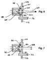
- FIGS. 6 and 7 show the body 28 with the wall 30 having longitudinal end (upper and lower) edges 106 and 108 of narrower cross-section than the section of the wall which receives the laser diode 58 and has the mirror or reflector surface 40.
- a collimating lens 65 and a focusing lens 66A is located in the aperture 64 and focuses the beam from the laser 58 in an image plane. The scanner is adjusted so that the bar code is located in the vicinity of this plane.
- the focusing lens 66A is preferably of "snap in" design so that the reading properties of the scan module may be tailored during the manufacturing process by selection of a suitable "snap in” lens.
- the laser diode 58 and lens 65 provide a collimated generally elliptical (with the major axis vertical) and no lens is used in the aperture 64.
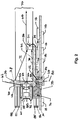
- a scan module 110 Like the scan module 12, it has a mounting board 112 on which an electro-optical scanning assembly 114 is rotatably mounted on flexure pairs 116 and 118.
- the mounting board 112 has wiring and circuit elements 118 thereon.
- the assembly 114 has a flex board 120 with wiring and circuit elements 122.
- the assembly 114 has an upstanding wall 124 and a platform 126.
- the wall 124 is narrowed in cross-section at its longitudinal ends 127 and 128.
- the side edges 130 and 132 of the wall at these ends 127 and 128 have the center of the flexure pairs 116 and 118 connected thereto.
- the flexure pairs 116 and 118 are each are a pair of bands of spring material such as phosphor bronze, stainless steel or beryllium copper.
- the flexure bands 134 and 136 of the flexure pair 116 are shown in FIG. 9. It will be appreciated that the flexure pair 118 has another pair of such band flexures symmetrically disposed about the lateral central plane of the device 110 when the assembly 114 is in its center or rest position (non-rotating).
- Each of these bands is of the same shape, specifically shown to be of the general shape of the letter "W" with the apex of the W connected to the edges 130 and 132.
- Flexures of shapes other than the "W" shape may also be used, e.g., each of the sections between the posts and the edges may be “S” shaped.
- the outer ends of the flexures are connected to posts 140, 142, 144 and 146.
- the assembly 114 is supported by the flexures so that it has an axis of rotation 160 through the center of mass of the assembly 114.
- the spring mass relationships of the flexures and the assembly 114 are preferably such that it is resonant at the scanning rate.
- An electromagnetic driver having coils 162 and a magnet 164 which is part of the assembly 114 is used to oscillate or nutate the assembly thereby scanning the beam 152 and also the photodetector 166 which receives the reflected light off a mirror on the forward surface 168 of the wall 124.
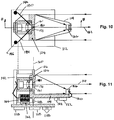
- FIGS. 10 and 11 there is shown another embodiment of the invention which is similar to the embodiment shown in FIG. 8, and to the extent of such similarity, like parts are labeled with like reference numerals.
- the flexural support for the assembly 114 in the embodiment of FIGS. 10 and 11, is provided by two pairs 180 and 181 of flexure bands which extend between the wall 124 and the posts 142 and 146.
- the bands are of stainless steel, phosphor bronze or beryllium copper and extend between the posts and the regions of the wall 124 at the longitudinal edges 126 and 128 thereof.
- the bands are embedded in these edge regions 126 and 128 on opposite sides of the axis 160 of rotation just to the rear of the aperture 161 through which the scanning beam 152 projects.
- This flexural support arrangement reduces the profile of the device forwardly of the axis of rotation and provides cost reduction by virtue of the greater simplicity of the flexural support.
- a cylindrical lens 171 is preferably located in the aperture 161 with its cylindrical axis along the axis of rotation 160. This lens will define the beam 152 as an oblong beam wider along the direction of the axis than in a direction perpendicular thereto. Such a beam will be longer in the direction of the bars of the code being scanned.
- the flexures provide stiffness in every direction (X, Y, Z axes) about the center of mass of the scanning assembly, and therefore robustness even against shock loads.
- the longitudinal stack of flexures provides stiffness along the axis of rotation.
- the flexures also provide stiffness in planes mutually perpendicular to the axis of rotation.
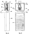
- a terminal 179 for collection of data has a unit 180 with a keyboard for manual entry of data.
- the design of the unit may be conventional. It has batteries and is adapted to be held in one hand by an operator.
- the other part of the terminal is a scan module 182.
- the module has an assembly 184 in a housing 186.
- the assembly 184 is similar in design to the assembly 26 and board 14 shown in FIGS. 1-4. Scanning assemblies of the designs shown in the other FIGS. may also be used.
- the module 182 and the unit 180 have mating connectors 188 which mechanically and electrically connect them together.
- the housing 186 has a base section 192 with a grommet 189 around the edge of the rectangular circuit board 190 of the assembly 184.
- the housing has an upper section 193 which slips or is latched on the lower housing section and captures the board 190 and grommet 189.
- the grommet is made of rubber or other elastomeric material and shock mounts the assembly 184
- a strain relief member of sheet metal is disposed within the housing of a modular connector having a locking bar which ordinarily is crimped into locking engagement with the wires of a multi-wire cable.
- the strain relief member has a tray portion over which the wires extend to contacts located near one end of the housing.
- a stem extends rearwardly from the tray portion out the housing and has arms which are crimped around the cable thereby providing strain relief.
- the tray has a slot therein which is disposed in alignment with the locking bar. When the locking bar is crimped, it fastens the strain relief member to the housing.
- a multi-wire cable may comprise any suitable plurality of wires.
- Z-shaped also includes any shape that is substantially Z-shaped.
Landscapes
- Physics & Mathematics (AREA)
- Electromagnetism (AREA)
- Engineering & Computer Science (AREA)
- Health & Medical Sciences (AREA)
- General Health & Medical Sciences (AREA)
- Toxicology (AREA)
- Artificial Intelligence (AREA)
- Computer Vision & Pattern Recognition (AREA)
- General Physics & Mathematics (AREA)
- Theoretical Computer Science (AREA)
- Mechanical Optical Scanning Systems (AREA)
Applications Claiming Priority (2)
| Application Number | Priority Date | Filing Date | Title |
|---|---|---|---|
| US07/543,950 US5115120A (en) | 1990-06-26 | 1990-06-26 | Scan modules for bar code readers and in which scan elements are flexurally supported |
| US543950 | 1995-10-17 |
Publications (2)
| Publication Number | Publication Date |
|---|---|
| EP0464284A2 true EP0464284A2 (de) | 1992-01-08 |
| EP0464284A3 EP0464284A3 (en) | 1993-05-12 |
Family
ID=24170183
Family Applications (1)
| Application Number | Title | Priority Date | Filing Date |
|---|---|---|---|
| EP19900313770 Withdrawn EP0464284A3 (en) | 1990-06-26 | 1990-12-17 | Scan modules for bar code readers |
Country Status (3)
| Country | Link |
|---|---|
| US (1) | US5115120A (de) |
| EP (1) | EP0464284A3 (de) |
| JP (1) | JP2732459B2 (de) |
Cited By (4)
| Publication number | Priority date | Publication date | Assignee | Title |
|---|---|---|---|---|
| EP0590537A3 (en) * | 1992-09-29 | 1996-02-07 | Symbol Technologies Inc | Slim-line module with interchangeable x-y scan element |
| WO1999056234A1 (en) * | 1998-04-29 | 1999-11-04 | Psc Inc. | Scanner having movable laser, detector arrangement and two flexures |
| WO2000072231A3 (en) * | 1999-05-21 | 2001-04-19 | Psc Scanning Inc | Wedged-shape holographic collector |
| EP0945818A3 (de) * | 1998-03-24 | 2001-10-17 | Symbol Technologies, Inc. | Streifencodeleser für tragbare Komputer |
Families Citing this family (44)
| Publication number | Priority date | Publication date | Assignee | Title |
|---|---|---|---|---|
| US5448046A (en) * | 1987-12-28 | 1995-09-05 | Symbol Technologies, Inc. | Arrangement for and method of expediting commercial product transactions at a point-of-sale site |
| US5410140A (en) * | 1988-05-11 | 1995-04-25 | Symbol Technologies, Inc. | Mirrorless ring mounted miniature optical scanner |
| US5254844A (en) * | 1988-05-11 | 1993-10-19 | Symbol Technologies, Inc. | Mirrorless scanners with movable laser, optical and sensor components |
| US5374817A (en) * | 1988-05-11 | 1994-12-20 | Symbol Technologies, Inc. | Pre-objective scanner with flexible optical support |
| US5587577A (en) * | 1989-06-08 | 1996-12-24 | Norand Corporation | Modular scanner with hand-held data terminal |
| US5552592A (en) * | 1989-10-30 | 1996-09-03 | Symbol Technologies, Inc. | Slim scan module with dual detectors |
| US6283372B1 (en) * | 1990-05-08 | 2001-09-04 | Symbol Technologies, Inc. | Electro-optical scanning assembly with conductive flexures |
| US5705799A (en) * | 1990-05-08 | 1998-01-06 | Symbol Technologies, Inc. | Miniature optical scanning assembly for barcode readers |
| US5581067A (en) * | 1990-05-08 | 1996-12-03 | Symbol Technologies, Inc. | Compact bar code scanning module with shock protection |
| US5392150A (en) * | 1991-05-15 | 1995-02-21 | Nippondenso Co., Ltd. | Optical information reading device |
| US5563402A (en) | 1991-11-04 | 1996-10-08 | Spectra-Physics Scanning Systems, Inc. | Multiple-interface selection for computer peripherals |
| US6000619A (en) * | 1992-02-21 | 1999-12-14 | Spectra-Physics Scanning Systems, Inc. | Scanner assembly |
| US6036093A (en) * | 1992-04-23 | 2000-03-14 | Intermec Ip Corp. | Modular scanner with hand-held data terminal |
| BR9307581A (pt) * | 1992-12-04 | 1999-08-31 | Psc Inc | Acessório de varredura para um terminal portátil para coletar e entrar com dados, motor de varredura e receptor eletro-ótico |
| US5422472A (en) * | 1992-12-04 | 1995-06-06 | Psc, Inc. | Optical symbol (bar code) reading systems having an electro-optic receptor with embedded grating rings |
| US5629510A (en) * | 1992-12-04 | 1997-05-13 | Psc Inc. | Bar code scanning and reading apparatus with an oscillating scanning engine |
| US5664231A (en) * | 1994-04-29 | 1997-09-02 | Tps Electronics | PCMCIA interface card for coupling input devices such as barcode scanning engines to personal digital assistants and palmtop computers |
| US5614705A (en) * | 1994-06-29 | 1997-03-25 | Olympus Optical Co., Ltd. | Device for optically reading out information by use of laser beam |
| US5512744A (en) * | 1994-09-26 | 1996-04-30 | Allen-Bradley Company, Inc. | Tapered beam folded cross flexure suspension |
| US5532480A (en) * | 1994-09-26 | 1996-07-02 | Allen-Bradley Company, Inc. | Dynamic damper for an oscillating mirror in a code reader |
| US5484995A (en) * | 1994-09-26 | 1996-01-16 | Allen-Bradley Company, Inc. | Pulse drive circuit for bar code reader resonant oscillator |
| US5539192A (en) * | 1994-09-26 | 1996-07-23 | Allen-Bradley Company, Inc. | Bar code reader mirror oscillator |
| WO1996013892A1 (en) * | 1994-10-31 | 1996-05-09 | Psc Inc. | System for driving and controlling the motion of an oscillatory electromechanical system especially suitable for use in an optical scanner |
| JP2774955B2 (ja) * | 1994-11-01 | 1998-07-09 | 富士通株式会社 | 周囲光検出装置,光源点灯制御装置および読取装置 |
| US5576530A (en) * | 1995-05-11 | 1996-11-19 | Universal Data Incorporated | Portable data terminal including a scanning head that is secured to the terminal in a manner that allows the scanning head to be positioned in opposite orientations |
| US5816689A (en) * | 1996-07-22 | 1998-10-06 | Strazzabosco; Frank | Apparatus and associated method for creating a broad area of illumination |
| US5912452A (en) * | 1997-02-06 | 1999-06-15 | Intermec Corporation | Method and apparatus for reading one-and two-dimensional symbols with a linear detector |
| US6131815A (en) * | 1997-09-29 | 2000-10-17 | Intermec Technologies Corporation | Slide-in tray for scanning device |
| JPH11112097A (ja) * | 1997-09-30 | 1999-04-23 | Fujitsu Ltd | 光源モジュールおよび光走査装置 |
| EP1354471A4 (de) * | 2000-12-15 | 2006-02-08 | Leonard Reiffel | Produkt zur codierten datenquellendateneingabe für mehrfach-abbildungsvorrichtung, mehrfach-quelle, mehrfach-benutzung |
| US6637657B2 (en) * | 2001-04-06 | 2003-10-28 | Symbol Technologies, Inc. | Compact scan module with magnetically centered scan mirror |
| WO2002086807A1 (en) * | 2001-04-19 | 2002-10-31 | Leonard Reiffel | Combined imaging coded data source data acquisition |
| EP1274039B1 (de) * | 2001-07-03 | 2008-01-02 | Symbol Technologies, Inc. | Kompaktes Scannermodul mit magnetisch zentriertem Abtastspiegel |
| US6578765B2 (en) | 2001-09-12 | 2003-06-17 | Psc Scanning, Inc. | Optical scanning system and integrated optics module therefor |
| US6788875B1 (en) * | 2002-04-08 | 2004-09-07 | Logitech Europe S.A. | Suspension system for use in an optical displacement detection system |
| US20060291797A1 (en) * | 2003-05-27 | 2006-12-28 | Leonard Reiffel | Multi-imager multi-source multi-use coded data source data input product |
| US8002183B2 (en) * | 2005-10-20 | 2011-08-23 | Metrologic Instruments, Inc. | Scanner flipper integrity indicator |
| US7832641B2 (en) * | 2007-05-24 | 2010-11-16 | Metrologic Instruments, Inc. | Scanner switched to active state by sensed movement in quiescent scanning mechanism |
| US8390909B2 (en) | 2009-09-23 | 2013-03-05 | Metrologic Instruments, Inc. | Molded elastomeric flexural elements for use in a laser scanning assemblies and scanners, and methods of manufacturing, tuning and adjusting the same |
| US8294969B2 (en) | 2009-09-23 | 2012-10-23 | Metrologic Instruments, Inc. | Scan element for use in scanning light and method of making the same |
| US8059324B2 (en) * | 2009-09-23 | 2011-11-15 | Metrologic Instruments, Inc. | Scan element for use in scanning light and method of making the same |
| US8915439B2 (en) | 2012-02-06 | 2014-12-23 | Metrologic Instruments, Inc. | Laser scanning modules embodying silicone scan element with torsional hinges |
| US8746563B2 (en) | 2012-06-10 | 2014-06-10 | Metrologic Instruments, Inc. | Laser scanning module with rotatably adjustable laser scanning assembly |
| CN112171588A (zh) * | 2020-09-23 | 2021-01-05 | 江苏洛柳精密科技有限公司 | 一种ccd扫码装置 |
Family Cites Families (22)
| Publication number | Priority date | Publication date | Assignee | Title |
|---|---|---|---|---|
| GB1388121A (en) * | 1972-02-25 | 1975-03-26 | Gb Sec Of State Environment | Marking of carriageways |
| JPS598892B2 (ja) * | 1975-06-19 | 1984-02-28 | ソニー株式会社 | 信号の光学的記録再生装置 |
| NL174609C (nl) * | 1975-10-15 | 1984-07-02 | Philips Nv | Volgspiegelinrichting in een optische platenspeler. |
| NL7703232A (nl) * | 1977-03-25 | 1978-09-27 | Philips Nv | Optische aftastinrichting. |
| NL7713711A (nl) * | 1977-12-12 | 1979-06-14 | Philips Nv | Optisch uitleeseenheid voor het uitlezen van een bewegende informatiedrager, in het bijzonder voor het uitlezen van een videoplaat. |
| US4667255A (en) * | 1979-09-24 | 1987-05-19 | Datacopy Corporation | Electronic camera employing a solid-state image sensor |
| CA1132258A (en) * | 1980-05-12 | 1982-09-21 | Herman W. Willemsen | Scanning head for an optical disc system |
| JPS5850336A (ja) * | 1981-09-17 | 1983-03-24 | Matsushita Electric Ind Co Ltd | 可動体保持装置 |
| US4578571A (en) * | 1983-11-14 | 1986-03-25 | Numa Corporation | Portable bar code scanning device and method |
| JPS6234338A (ja) * | 1985-08-08 | 1987-02-14 | Olympus Optical Co Ltd | 対物レンズ駆動装置 |
| US4621189A (en) * | 1985-10-08 | 1986-11-04 | Telxon Corporation | Hand held data entry apparatus |
| US4732440A (en) * | 1985-10-22 | 1988-03-22 | Gadhok Jagmohan S | Self resonant scanning device |
| US4750164A (en) * | 1985-12-09 | 1988-06-07 | Canon Kabushiki Kaisha | Optical system driving device |
| US5059778A (en) * | 1986-09-29 | 1991-10-22 | Mars Incorporated | Portable data scanner apparatus |
| JPS63195834A (ja) * | 1987-02-10 | 1988-08-12 | Pioneer Electronic Corp | 可動体支持装置 |
| US4805175A (en) * | 1987-12-03 | 1989-02-14 | Metrologic Instrumetns, Inc. | Ultra-compact, hand-held laser scanner |
| US4861125A (en) * | 1988-05-06 | 1989-08-29 | Tencor Instruments | Suspension assembly for a scanning mirror |
| US5144120A (en) * | 1988-05-11 | 1992-09-01 | Symbol Technologies, Inc. | Mirrorless scanners with movable laser, optical and sensor components |
| US4902083A (en) * | 1988-05-31 | 1990-02-20 | Reflection Technology, Inc. | Low vibration resonant scanning unit for miniature optical display apparatus |
| JPH0223428A (ja) * | 1988-07-12 | 1990-01-25 | Nec Corp | コマンド型エンドユーザ言語の翻訳型実行方式 |
| US5015831A (en) * | 1988-11-07 | 1991-05-14 | Photographic Sciences Corporation | Scan modules for bar code readers and the like in which scan elements are flexurally supported |
| US4983818A (en) * | 1989-01-30 | 1991-01-08 | Metrologic Instruments, Inc. | Data acquisition system with laser scanner module |
-
1990
- 1990-06-26 US US07/543,950 patent/US5115120A/en not_active Expired - Lifetime
- 1990-12-17 EP EP19900313770 patent/EP0464284A3/en not_active Withdrawn
-
1991
- 1991-06-25 JP JP3180206A patent/JP2732459B2/ja not_active Expired - Lifetime
Cited By (4)
| Publication number | Priority date | Publication date | Assignee | Title |
|---|---|---|---|---|
| EP0590537A3 (en) * | 1992-09-29 | 1996-02-07 | Symbol Technologies Inc | Slim-line module with interchangeable x-y scan element |
| EP0945818A3 (de) * | 1998-03-24 | 2001-10-17 | Symbol Technologies, Inc. | Streifencodeleser für tragbare Komputer |
| WO1999056234A1 (en) * | 1998-04-29 | 1999-11-04 | Psc Inc. | Scanner having movable laser, detector arrangement and two flexures |
| WO2000072231A3 (en) * | 1999-05-21 | 2001-04-19 | Psc Scanning Inc | Wedged-shape holographic collector |
Also Published As
| Publication number | Publication date |
|---|---|
| JP2732459B2 (ja) | 1998-03-30 |
| EP0464284A3 (en) | 1993-05-12 |
| JPH04348489A (ja) | 1992-12-03 |
| US5115120A (en) | 1992-05-19 |
Similar Documents
| Publication | Publication Date | Title |
|---|---|---|
| EP0464284A2 (de) | Abtastmodule für Streifencodelaser | |
| US5629510A (en) | Bar code scanning and reading apparatus with an oscillating scanning engine | |
| EP0341717B1 (de) | Spiegelfreier Abtaster mit beweglicher Laserquelle und beweglichen, optischen Komponenten | |
| EP0653723B1 (de) | Abtastelement mit Stosschutz | |
| EP0368254B1 (de) | Abtastmodule für Streifencode-Leser und gleichartiges | |
| EP0455740B1 (de) | Tragbarer laserabtaster mit eingebautem abtastmodul | |
| US5583332A (en) | Compact scan module with oscillatable unitary assembly | |
| EP0319164A2 (de) | Laser-Abtaster | |
| US6592040B2 (en) | Hand-held bar code reader with single printed circuit board | |
| US5214270A (en) | Modular handheld or fixed scanner | |
| AU684569B2 (en) | Optical symbol (bar code) reading systems and devices | |
| EP0085804A2 (de) | Schmaler, mit Einzel- und Doppelfenstern versehener, tragbarer Laserabtastkopf zum Lesen von Strichkodensymbolen | |
| US5468952A (en) | Miniature high speed scan element mounted on a personal computer interface card | |
| EP0534222A2 (de) | Piezoelektrischer Strahlenablenker | |
| US6036098A (en) | Miniature scan element operably connected to a personal computer interface card | |
| EP1760514A1 (de) | Abtastgerät für einen optischen Code-Leser | |
| CN109815755B (zh) | 具有pcb的条形码扫描器 | |
| US6230976B1 (en) | Pinless dithering assembly for data reading | |
| US5708262A (en) | Miniature high speed scan element mounted on a personal computer interface card | |
| US6679429B2 (en) | Bar code scanning device | |
| US5177347A (en) | Axially invariant pattern scanning apparatus | |
| EP1903472A1 (de) | Optischer Scanner mit Optikmotor | |
| US8203616B2 (en) | Imaging scanner | |
| US7017815B2 (en) | Compact externally-driven scanner | |
| EP0405965A2 (de) | Detektoreinheit |
Legal Events
| Date | Code | Title | Description |
|---|---|---|---|
| PUAI | Public reference made under article 153(3) epc to a published international application that has entered the european phase |
Free format text: ORIGINAL CODE: 0009012 |
|
| AK | Designated contracting states |
Kind code of ref document: A2 Designated state(s): BE CH DE DK ES FR GB GR IT LI LU NL SE |
|
| 17P | Request for examination filed |
Effective date: 19920721 |
|
| PUAL | Search report despatched |
Free format text: ORIGINAL CODE: 0009013 |
|
| AK | Designated contracting states |
Kind code of ref document: A3 Designated state(s): BE CH DE DK ES FR GB GR IT LI LU NL SE |
|
| 17Q | First examination report despatched |
Effective date: 19940614 |
|
| GRAG | Despatch of communication of intention to grant |
Free format text: ORIGINAL CODE: EPIDOS AGRA |
|
| GRAG | Despatch of communication of intention to grant |
Free format text: ORIGINAL CODE: EPIDOS AGRA |
|
| GRAH | Despatch of communication of intention to grant a patent |
Free format text: ORIGINAL CODE: EPIDOS IGRA |
|
| STAA | Information on the status of an ep patent application or granted ep patent |
Free format text: STATUS: THE APPLICATION IS DEEMED TO BE WITHDRAWN |
|
| 18D | Application deemed to be withdrawn |
Effective date: 20010828 |