EP0464792A2 - AGC-Schaltung einer FM-Eingangsstufe - Google Patents
AGC-Schaltung einer FM-Eingangsstufe Download PDFInfo
- Publication number
- EP0464792A2 EP0464792A2 EP91111029A EP91111029A EP0464792A2 EP 0464792 A2 EP0464792 A2 EP 0464792A2 EP 91111029 A EP91111029 A EP 91111029A EP 91111029 A EP91111029 A EP 91111029A EP 0464792 A2 EP0464792 A2 EP 0464792A2
- Authority
- EP
- European Patent Office
- Prior art keywords
- signal
- accordance
- input
- agc
- circuit
- Prior art date
- Legal status (The legal status is an assumption and is not a legal conclusion. Google has not performed a legal analysis and makes no representation as to the accuracy of the status listed.)
- Granted
Links
- 230000005684 electric field Effects 0.000 claims abstract description 11
- 230000035945 sensitivity Effects 0.000 description 4
- 238000010586 diagram Methods 0.000 description 3
- 230000003321 amplification Effects 0.000 description 2
- 230000000694 effects Effects 0.000 description 2
- 238000003199 nucleic acid amplification method Methods 0.000 description 2
- 239000000919 ceramic Substances 0.000 description 1
- 238000007796 conventional method Methods 0.000 description 1
Images


Classifications
-
- H—ELECTRICITY
- H04—ELECTRIC COMMUNICATION TECHNIQUE
- H04B—TRANSMISSION
- H04B1/00—Details of transmission systems, not covered by a single one of groups H04B3/00 - H04B13/00; Details of transmission systems not characterised by the medium used for transmission
- H04B1/06—Receivers
- H04B1/10—Means associated with receiver for limiting or suppressing noise or interference
- H04B1/14—Automatic detuning arrangements
-
- H—ELECTRICITY
- H03—ELECTRONIC CIRCUITRY
- H03G—CONTROL OF AMPLIFICATION
- H03G3/00—Gain control in amplifiers or frequency changers
- H03G3/20—Automatic control
- H03G3/30—Automatic control in amplifiers having semiconductor devices
- H03G3/3052—Automatic control in amplifiers having semiconductor devices in bandpass amplifiers (H.F. or I.F.) or in frequency-changers used in a (super)heterodyne receiver
-
- H—ELECTRICITY
- H04—ELECTRIC COMMUNICATION TECHNIQUE
- H04B—TRANSMISSION
- H04B1/00—Details of transmission systems, not covered by a single one of groups H04B3/00 - H04B13/00; Details of transmission systems not characterised by the medium used for transmission
- H04B1/06—Receivers
- H04B1/16—Circuits
Definitions
- the present invention relates to an AGC (Automatic Gain Control) circuit of an FM front-end portion and, more particularly, to an AGC circuit of an FM front-end portion used in an FM tuner of mobile audio equipment.
- AGC Automatic Gain Control
- An AGC circuit of an FM front-end portion is generally operated by receiving an input signal having an amplitude exceeding an AGC sensitivity, and an AGC amount is determined in accordance with a difference between the AGC sensitivity and the input amplitude.
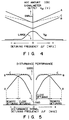
- the frequency characteristics of the AGC amount are shown in Fig. 1. For this reason, as shown in disturbance performance characteristics (when the AGC amount has the frequency characteristics in Fig. 1) in Fig. 2, when the AGC sensitivity is set to obtain improved disturbance performance in a close-detuning range, the AGC amount is very small (a solid line A in Fig. 1) in a remote-detuning range. As a result, the disturbance performance in the remote-detuning range is degraded (a solid line A in Fig. 2).
- the present invention has been made to solve the above drawback, and has as its object to provide an AGC circuit of an FM front-end portion capable of obtaining improved disturbance performance in both close- and remote-detuning ranges by making an AGC amount of the AGC circuit of the FM front-end portion to be changeable.
- an AGC circuit of an FM front-end portion comprising a first input amplitude control circuit for outputting third and fourth signals in accordance with a level of a receiving electric field strength of a receiver having an attenuator for attenuating an input signal in accordance with a level of a first signal and an amplifier for amplifying the input signal in accordance with a second signal, a receiving electric field delecting circuit for outputting a fifth signal in accordance with an amplitude of an IF signal in the receiver, and a second input amplitude control circuit for outputting the first and second signals by changing the third and fourth signals in accordance with the fifth signal.
- an AGC amount of the AGC circuit of the FM front-end portion is changed in accordance with the amplitude of the IF signal. For this reason, the AGC amount can be set to obtain improved disturbance performance in close- and remote-detuning ranges. That is, the improved disturbance performance can be obtained in both the close- and remote-detuning ranges.
- Fig. 3 is a block diagram showing a principle of an AGC circuit of an FM front-end portion according to the first embodiment of the present invention.
- a signal ⁇ 1 of an FM wave from an antenna is input to an attenuator 11.
- the signal ⁇ 1 is input from the attenuator 11 to an antenna tuner 12.
- the antenna tuner 12 has frequency characteristics including a reception frequency as a center (a maximum frequency).
- the input signal is amplified by a high frequency amplifier 13.
- the amplified input signal is input to an RF tuner 14.
- the RF tuner 14 has frequency characteristics including a reception frequency as a center (a maximum frequency).
- a signal ⁇ 2 output from the RF tuner 14 is input to a first input amplitude control circuit 15 and a mixer 16.
- the signal ⁇ 2 from the RF tuner 14 is mixed with a signal ⁇ 3 from a local oscillator (VCO) 17.
- An IF signal ⁇ 4 is output from the mixer 16 through an intermediate tuning transformer IFT (coil) 18 and a CF (ceramic filter) 19.
- the IF signal ⁇ 4 is input to an IF limiter amplifier 20, and an amplified IF signal ⁇ 5 is output from the IF limiter amplifier 20.
- an attenuation control signal (the third signal) ⁇ 6 is output from the first input amplitude control circuit 15, and the signal ⁇ 6 is input to a second input amplitude control circuit 22.
- the first input amplitude control circuit 15 can change the level of the attenuation control signal ⁇ 6 for determining an attenuation amount of the attenuator 11 and a gain amount of the amplifier 13 according to the level of the signal ⁇ 2.
- the signal meter output voltage V M having a voltage value determined in accordance with the amplitude of the IF signal ⁇ 4 is input from the IF limiter amplifier 20 to a receiving electric field detecting circuit 21, and a control signal (the fifth signal) ⁇ 8 is output from the receiving electric field detecting circuit 21.
- the control signal ⁇ 8 is input to the second input amplitude control circuit 22 such that the level of the attenuation control signal ⁇ 6 can be adjusted. Therefore, the attenuation control signal (the first signal) ⁇ 9 and the gain control signal (the second signal) ⁇ 10 which are corrected as requested are output from the second input amplitude control circuit 22.
- the attenuation control signal ⁇ 9 is input to the attenuator 11 to control the attenuation amount of the attenuator 11.
- a gain control signal ⁇ 10 is input to the RF amplifier 13 to control the amplification amount of the high frequency amplifier 13.
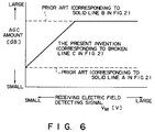
- the AGC amount of the AGC circuit of the FM front-end portion is changed such that the control signal ⁇ 8 is changed in accordance with the amplitude of the signal meter output voltage V M , i.e., the IF signal ⁇ 4, of an FM IF portion.
- the AGC amount can be set (a broken line C in Fig. 4) to obtain improved disturbance performance in close- and remote-detuning ranges.
- disturbance performance can be improved in the close- and remote-detuning ranges (a broken line C in Fig. 5).
- Fig. 6 shows a relationship between the signal meter output voltage V M of the FM IF portion and the AGC amount.
- Fig. 7 is a view showing an AGC circuit of an FM front-end portion according to the second embodiment of the present invention.
- the same reference numerals as in Fig. 3 denote the same parts in Fig. 7, and a description thereof will be omitted.
- an attenuation control signal (the first signal) ⁇ 11 is output from a first input amplitude control circuit 22 in accordance with the level of the signal ⁇ 2.
- the signal ⁇ 9 and a gain control signal (the second signal) ⁇ 10 are output from the second input amplitude control circuit 15.
- the level of the attenuation control signal ⁇ 9 for determining the attenuation amount of the attenuator 11 and the level of the gain control signal ⁇ 10 for determining the gain amount of an amplifier 13 can be changed.
- a signal meter output voltage V M having a voltage value determined in accordance with the amplitude of an IF signal ⁇ 4 is input from an IF limiter amplifier 20 to a receiving electric field detecting circuit 21, and a control signal (the third signal) ⁇ 8 is output from the control circuit 21.
- the signal ⁇ 8 is input to a first input amplitude circuit 22.
- a control signal (the fourth signal) ⁇ 11 for adjusting the level of the attenuation control signal ⁇ 9 or the gain control signal ⁇ 10 is output from the first input amplitude control circuit 22. That is, the attenuation control signal ⁇ 9 and the gain control signal ⁇ 10 can be adjusted in accordance with the control signal ⁇ 11.
- the attenuation control signal ⁇ 9 and the gain control signal ⁇ 10 which are corrected as needed are output from the first input amplitude control circuit 15. Note that the attenuation amount of the attenuator 11 is controlled by the attenuation control signal ⁇ 9, and the amplification amount of the RF amplifier 13 can be controlled by the gain control signal ⁇ 10.
- An AGC amount of an AGC circuit of the FM front-end portion can be changed by a signal meter output of the FM IF portion. For this reason, the AGC amount can be set to obtain improved disturbance performance in the close-and remote-detuning ranges.
Landscapes
- Engineering & Computer Science (AREA)
- Computer Networks & Wireless Communication (AREA)
- Signal Processing (AREA)
- Control Of Amplification And Gain Control (AREA)
- Circuits Of Receivers In General (AREA)
- Superheterodyne Receivers (AREA)
- Input Circuits Of Receivers And Coupling Of Receivers And Audio Equipment (AREA)
- Noise Elimination (AREA)
Applications Claiming Priority (2)
| Application Number | Priority Date | Filing Date | Title |
|---|---|---|---|
| JP2174509A JP2577490B2 (ja) | 1990-07-03 | 1990-07-03 | Fmフロントエンド部のagc回路 |
| JP174509/90 | 1990-07-03 |
Publications (3)
| Publication Number | Publication Date |
|---|---|
| EP0464792A2 true EP0464792A2 (de) | 1992-01-08 |
| EP0464792A3 EP0464792A3 (de) | 1994-01-19 |
| EP0464792B1 EP0464792B1 (de) | 1997-10-15 |
Family
ID=15979752
Family Applications (1)
| Application Number | Title | Priority Date | Filing Date |
|---|---|---|---|
| EP91111029A Expired - Lifetime EP0464792B1 (de) | 1990-07-03 | 1991-07-03 | AGC-Schaltung einer FM-Eingangsstufe |
Country Status (5)
| Country | Link |
|---|---|
| US (1) | US5369792A (de) |
| EP (1) | EP0464792B1 (de) |
| JP (1) | JP2577490B2 (de) |
| KR (1) | KR950004747B1 (de) |
| DE (1) | DE69127934T2 (de) |
Cited By (8)
| Publication number | Priority date | Publication date | Assignee | Title |
|---|---|---|---|---|
| US5270824A (en) * | 1991-12-30 | 1993-12-14 | Zenith Electronics Corporation | AGC circuit for double conversion digital television tuner |
| DE4303110A1 (de) * | 1993-02-04 | 1994-08-18 | Kolbe & Co Hans | Rundfunk-Empfangssystem |
| GB2342238A (en) * | 1998-09-30 | 2000-04-05 | Sony Uk Ltd | Digital terrestrial TV tuner |
| EP1179887A3 (de) * | 2000-08-03 | 2003-11-26 | Tektronix, Inc. | Verzerrungsüberlastschutz für einen Breitbandempfänger |
| EP0798850B1 (de) * | 1996-03-27 | 2004-10-13 | Philips Intellectual Property & Standards GmbH | Verbesserung in oder bezüglich Radioempfänger |
| EP1330024A3 (de) * | 2002-01-22 | 2005-05-18 | Alps Electric Co., Ltd. | Schaltung zur automatischen Verstärkungsregelung in einem FM-Empfänger |
| EP1355419A3 (de) * | 2002-04-16 | 2005-05-25 | Matsushita Electric Industrial Co., Ltd. | Hochfrequenzsignalempfänger |
| CN108112068A (zh) * | 2017-12-04 | 2018-06-01 | 中国电子科技集团公司第三十研究所 | 一种适用于ofdm系统的快速自动增益控制方法 |
Families Citing this family (23)
| Publication number | Priority date | Publication date | Assignee | Title |
|---|---|---|---|---|
| US5481226A (en) * | 1994-10-25 | 1996-01-02 | Motorola, Inc. | Low-voltage intermediate frequency amplifier providing automatic gain control of a source amplifier |
| US5722063A (en) * | 1994-12-16 | 1998-02-24 | Qualcomm Incorporated | Method and apparatus for increasing receiver immunity to interference |
| KR0168790B1 (ko) * | 1995-07-06 | 1999-02-01 | 김광호 | 수신신호세기의 동적범위를 확장시키는 셀룰라 통신시스템의 수신기 |
| US5697081A (en) * | 1995-09-12 | 1997-12-09 | Oki Telecom, Inc. | Intermodulation distortion reduction circuit utilizing variable attenuation |
| DE69731137T2 (de) * | 1996-03-27 | 2006-03-09 | Philips Intellectual Property & Standards Gmbh | Verbesserung in oder bezüglich Radioempfänger |
| US5745844A (en) * | 1996-10-04 | 1998-04-28 | Motorola, Inc. | Receiver control in a communication device by antenna de-tuning in strong signal conditions, and method therefor |
| JPH10276109A (ja) * | 1997-03-27 | 1998-10-13 | Alps Electric Co Ltd | テレビジョン信号受信用チュ−ナ |
| JPH10276112A (ja) * | 1997-03-28 | 1998-10-13 | Sanyo Electric Co Ltd | ラジオ受信機 |
| JPH10276125A (ja) * | 1997-03-28 | 1998-10-13 | Matsushita Electric Ind Co Ltd | 移動無線受信装置 |
| US6236863B1 (en) * | 1997-03-31 | 2001-05-22 | Oki Telecom, Inc. | Comprehensive transmitter power control system for radio telephones |
| JPH11136142A (ja) * | 1997-11-03 | 1999-05-21 | Nec Shizuoka Ltd | 利得制御回路及び利得制御方法 |
| JPH11154882A (ja) * | 1997-11-21 | 1999-06-08 | Hitachi Denshi Ltd | 無線機 |
| US6212244B1 (en) * | 1998-01-09 | 2001-04-03 | Golden Bridge Technology, Inc. | Fast response automatic gain control |
| JP3604274B2 (ja) * | 1998-03-10 | 2004-12-22 | パイオニア株式会社 | Rf−agc回路を備えた受信機 |
| JP3121319B2 (ja) * | 1998-12-17 | 2000-12-25 | 日本電気株式会社 | Ds−cdmaマルチユーザ干渉キャンセラとそのシステム |
| US6229998B1 (en) | 1999-04-12 | 2001-05-08 | Qualcomm Inc. | Method and system for detecting in-band jammers in a spread spectrum wireless base station |
| DE10005605B4 (de) * | 2000-02-09 | 2004-04-08 | Infineon Technologies Ag | Analoge Vorstufe |
| DE10025837A1 (de) * | 2000-05-25 | 2001-12-13 | Rohde & Schwarz | Breitbandempfänger |
| US6961552B2 (en) * | 2002-03-25 | 2005-11-01 | Broadcom Corporation | LNA gain adjustment for intermodulation interference reduction |
| US20040162043A1 (en) * | 2003-02-14 | 2004-08-19 | Motorola, Inc. | System and method for compensating receiver gain using a mixed signal technique by implementing both automatic gain control (AGC) and bit-normalization |
| JP4719139B2 (ja) * | 2006-12-05 | 2011-07-06 | トヨタ自動車株式会社 | 中空バルブ |
| JP4844847B2 (ja) * | 2008-03-17 | 2011-12-28 | トヨタ自動車株式会社 | 中空バルブ |
| US10931321B1 (en) | 2020-01-08 | 2021-02-23 | Eagle Technology, Llc | System and method for optimizing intermodulation performance of receivers |
Family Cites Families (14)
| Publication number | Priority date | Publication date | Assignee | Title |
|---|---|---|---|---|
| JPS5345250B2 (de) * | 1974-10-02 | 1978-12-05 | ||
| US4013964A (en) * | 1975-10-22 | 1977-03-22 | Motorola, Inc. | Automatic gain control means for a single sideband radio receiver |
| JPS583331A (ja) * | 1981-06-29 | 1983-01-10 | Hitachi Ltd | Agc回路 |
| JPS5928711A (ja) * | 1982-08-09 | 1984-02-15 | Matsushita Electric Ind Co Ltd | 受信装置 |
| JPS59212038A (ja) * | 1983-05-18 | 1984-11-30 | Pioneer Electronic Corp | 受信装置 |
| US4538300A (en) * | 1983-09-07 | 1985-08-27 | Sprague Electric Company | Linear signal strength detector in AM radio |
| JPS6137620U (ja) * | 1984-08-10 | 1986-03-08 | アルパイン株式会社 | ラジオ受信機 |
| JPH01129620A (ja) * | 1987-11-16 | 1989-05-22 | Sanyo Electric Co Ltd | ラジオ受信機 |
| JPH01133409A (ja) * | 1987-11-19 | 1989-05-25 | Sanyo Electric Co Ltd | オートサーチチューナ |
| DE69032634T2 (de) * | 1989-06-27 | 1999-01-28 | Nec Corp., Tokio/Tokyo | Steuerschaltung für die Ausgangswellenform |
| JPH0338906A (ja) * | 1989-07-05 | 1991-02-20 | Pioneer Electron Corp | 受信装置 |
| JPH0795699B2 (ja) * | 1989-10-26 | 1995-10-11 | 松下電器産業株式会社 | 受信機 |
| JP2589202B2 (ja) * | 1990-06-29 | 1997-03-12 | 三洋電機株式会社 | ラジオ用感度切換え回路 |
| EP0464669B1 (de) * | 1990-06-29 | 1997-06-04 | Sanyo Electric Co., Ltd. | Automatische Verstärkungsregelung für einen Radioempfänger |
-
1990
- 1990-07-03 JP JP2174509A patent/JP2577490B2/ja not_active Expired - Lifetime
-
1991
- 1991-07-02 KR KR1019910011160A patent/KR950004747B1/ko not_active Expired - Lifetime
- 1991-07-03 EP EP91111029A patent/EP0464792B1/de not_active Expired - Lifetime
- 1991-07-03 DE DE69127934T patent/DE69127934T2/de not_active Expired - Lifetime
- 1991-07-03 US US07/725,522 patent/US5369792A/en not_active Expired - Lifetime
Cited By (11)
| Publication number | Priority date | Publication date | Assignee | Title |
|---|---|---|---|---|
| US5270824A (en) * | 1991-12-30 | 1993-12-14 | Zenith Electronics Corporation | AGC circuit for double conversion digital television tuner |
| DE4303110A1 (de) * | 1993-02-04 | 1994-08-18 | Kolbe & Co Hans | Rundfunk-Empfangssystem |
| EP0798850B1 (de) * | 1996-03-27 | 2004-10-13 | Philips Intellectual Property & Standards GmbH | Verbesserung in oder bezüglich Radioempfänger |
| GB2342238A (en) * | 1998-09-30 | 2000-04-05 | Sony Uk Ltd | Digital terrestrial TV tuner |
| EP1179887A3 (de) * | 2000-08-03 | 2003-11-26 | Tektronix, Inc. | Verzerrungsüberlastschutz für einen Breitbandempfänger |
| EP1330024A3 (de) * | 2002-01-22 | 2005-05-18 | Alps Electric Co., Ltd. | Schaltung zur automatischen Verstärkungsregelung in einem FM-Empfänger |
| US7050774B2 (en) | 2002-01-22 | 2006-05-23 | Alps Electric Co., Ltd. | AGC circuit of an FM receiver that reduces interference while maintaining high reception sensitivity |
| EP1355419A3 (de) * | 2002-04-16 | 2005-05-25 | Matsushita Electric Industrial Co., Ltd. | Hochfrequenzsignalempfänger |
| US7187733B2 (en) | 2002-04-16 | 2007-03-06 | Matsushita Electric Industrial Co., Ltd. | High-frequency signal receiver |
| CN108112068A (zh) * | 2017-12-04 | 2018-06-01 | 中国电子科技集团公司第三十研究所 | 一种适用于ofdm系统的快速自动增益控制方法 |
| CN108112068B (zh) * | 2017-12-04 | 2020-12-11 | 中国电子科技集团公司第三十研究所 | 一种适用于ofdm系统的快速自动增益控制方法 |
Also Published As
| Publication number | Publication date |
|---|---|
| EP0464792A3 (de) | 1994-01-19 |
| DE69127934D1 (de) | 1997-11-20 |
| KR920003678A (ko) | 1992-02-29 |
| KR950004747B1 (ko) | 1995-05-06 |
| EP0464792B1 (de) | 1997-10-15 |
| JP2577490B2 (ja) | 1997-01-29 |
| DE69127934T2 (de) | 1998-03-05 |
| JPH0465907A (ja) | 1992-03-02 |
| US5369792A (en) | 1994-11-29 |
Similar Documents
| Publication | Publication Date | Title |
|---|---|---|
| EP0464792A2 (de) | AGC-Schaltung einer FM-Eingangsstufe | |
| US4553105A (en) | Multistage linear amplifier for a wide range of input signal levels | |
| KR100382192B1 (ko) | 튜너용자동이득제어회로장치 | |
| US3728633A (en) | Radio receiver with wide dynamic range | |
| US4989264A (en) | Bandwidth limiting circuit with variable bandwidth | |
| US3939428A (en) | Receiver with automatic pass band control | |
| US2630527A (en) | Interchannel noise suppressor circuits | |
| EP1383318B1 (de) | Beseitigung des Einflusses von analogen Signalen während des Empfangs von digitalen Signalen in einem Fernsehtuner | |
| US5303410A (en) | Signal strength meter circuit for radio receiver | |
| JPH0752851B2 (ja) | Fm受信装置 | |
| EP0795967A1 (de) | Verfahren zur Energieeinsparung in einem Funkempfänger | |
| KR0177676B1 (ko) | 자동이득 제어 지연점 조정회로 | |
| JP3174230B2 (ja) | ラジオ受信機 | |
| KR0133242Y1 (ko) | 강전계영역을 보완한 위성방송 튜너 | |
| JP2807360B2 (ja) | 受信装置 | |
| JPH0746988Y2 (ja) | Fm受信機のagc制御回路 | |
| RU2052896C1 (ru) | Радиоприемник амплитудно-модулированных сигналов с подавлением интермодуляционных помех | |
| KR200179114Y1 (ko) | 위성방송 수신기의 자동이득 제어회로 | |
| KR0176633B1 (ko) | 디지탈 텔레비젼 수상기의 2중 자동 이득 조절회로 | |
| JPS6041331A (ja) | ラジオ受信機 | |
| KR960004509B1 (ko) | 텔레비젼 방송신호 수신회로 | |
| EP0388552A2 (de) | Empfänger | |
| JP2519320Y2 (ja) | チューナのagc回路 | |
| GB2093291A (en) | Gain Control Circuit for High Frequency and Intermediate Frequency Stages in Radio or Television Receivers | |
| JPS628975B2 (de) |
Legal Events
| Date | Code | Title | Description |
|---|---|---|---|
| PUAI | Public reference made under article 153(3) epc to a published international application that has entered the european phase |
Free format text: ORIGINAL CODE: 0009012 |
|
| 17P | Request for examination filed |
Effective date: 19910703 |
|
| AK | Designated contracting states |
Kind code of ref document: A2 Designated state(s): DE FR GB |
|
| PUAL | Search report despatched |
Free format text: ORIGINAL CODE: 0009013 |
|
| AK | Designated contracting states |
Kind code of ref document: A3 Designated state(s): DE FR GB |
|
| 17Q | First examination report despatched |
Effective date: 19950328 |
|
| GRAG | Despatch of communication of intention to grant |
Free format text: ORIGINAL CODE: EPIDOS AGRA |
|
| GRAH | Despatch of communication of intention to grant a patent |
Free format text: ORIGINAL CODE: EPIDOS IGRA |
|
| GRAH | Despatch of communication of intention to grant a patent |
Free format text: ORIGINAL CODE: EPIDOS IGRA |
|
| GRAA | (expected) grant |
Free format text: ORIGINAL CODE: 0009210 |
|
| AK | Designated contracting states |
Kind code of ref document: B1 Designated state(s): DE FR GB |
|
| REF | Corresponds to: |
Ref document number: 69127934 Country of ref document: DE Date of ref document: 19971120 |
|
| ET | Fr: translation filed | ||
| PLBE | No opposition filed within time limit |
Free format text: ORIGINAL CODE: 0009261 |
|
| STAA | Information on the status of an ep patent application or granted ep patent |
Free format text: STATUS: NO OPPOSITION FILED WITHIN TIME LIMIT |
|
| 26N | No opposition filed | ||
| REG | Reference to a national code |
Ref country code: GB Ref legal event code: 746 Effective date: 19981015 |
|
| REG | Reference to a national code |
Ref country code: FR Ref legal event code: D6 |
|
| REG | Reference to a national code |
Ref country code: GB Ref legal event code: IF02 |
|
| PGFP | Annual fee paid to national office [announced via postgrant information from national office to epo] |
Ref country code: GB Payment date: 20100630 Year of fee payment: 20 Ref country code: DE Payment date: 20100630 Year of fee payment: 20 Ref country code: FR Payment date: 20100805 Year of fee payment: 20 |
|
| REG | Reference to a national code |
Ref country code: DE Ref legal event code: R071 Ref document number: 69127934 Country of ref document: DE |
|
| REG | Reference to a national code |
Ref country code: DE Ref legal event code: R071 Ref document number: 69127934 Country of ref document: DE |
|
| REG | Reference to a national code |
Ref country code: GB Ref legal event code: PE20 Expiry date: 20110702 |
|
| PG25 | Lapsed in a contracting state [announced via postgrant information from national office to epo] |
Ref country code: GB Free format text: LAPSE BECAUSE OF EXPIRATION OF PROTECTION Effective date: 20110702 |
|
| PG25 | Lapsed in a contracting state [announced via postgrant information from national office to epo] |
Ref country code: DE Free format text: LAPSE BECAUSE OF EXPIRATION OF PROTECTION Effective date: 20110704 |