EP0464827A2 - Support d'enregistrement magnétique et sa méthode de fabrication - Google Patents
Support d'enregistrement magnétique et sa méthode de fabrication Download PDFInfo
- Publication number
- EP0464827A2 EP0464827A2 EP91111149A EP91111149A EP0464827A2 EP 0464827 A2 EP0464827 A2 EP 0464827A2 EP 91111149 A EP91111149 A EP 91111149A EP 91111149 A EP91111149 A EP 91111149A EP 0464827 A2 EP0464827 A2 EP 0464827A2
- Authority
- EP
- European Patent Office
- Prior art keywords
- magnetic recording
- recording medium
- coat layer
- back coat
- accordance
- Prior art date
- Legal status (The legal status is an assumption and is not a legal conclusion. Google has not performed a legal analysis and makes no representation as to the accuracy of the status listed.)
- Granted
Links
Images





Classifications
-
- G—PHYSICS
- G11—INFORMATION STORAGE
- G11B—INFORMATION STORAGE BASED ON RELATIVE MOVEMENT BETWEEN RECORD CARRIER AND TRANSDUCER
- G11B5/00—Recording by magnetisation or demagnetisation of a record carrier; Reproducing by magnetic means; Record carriers therefor
- G11B5/62—Record carriers characterised by the selection of the material
- G11B5/73—Base layers, i.e. all non-magnetic layers lying under a lowermost magnetic recording layer, e.g. including any non-magnetic layer in between a first magnetic recording layer and either an underlying substrate or a soft magnetic underlayer
- G11B5/735—Base layers, i.e. all non-magnetic layers lying under a lowermost magnetic recording layer, e.g. including any non-magnetic layer in between a first magnetic recording layer and either an underlying substrate or a soft magnetic underlayer characterised by the back layer
- G11B5/7356—Base layers, i.e. all non-magnetic layers lying under a lowermost magnetic recording layer, e.g. including any non-magnetic layer in between a first magnetic recording layer and either an underlying substrate or a soft magnetic underlayer characterised by the back layer comprising non-magnetic particles in the back layer, e.g. particles of TiO2, ZnO or SiO2
-
- G—PHYSICS
- G11—INFORMATION STORAGE
- G11B—INFORMATION STORAGE BASED ON RELATIVE MOVEMENT BETWEEN RECORD CARRIER AND TRANSDUCER
- G11B5/00—Recording by magnetisation or demagnetisation of a record carrier; Reproducing by magnetic means; Record carriers therefor
- G11B5/84—Processes or apparatus specially adapted for manufacturing record carriers
-
- Y—GENERAL TAGGING OF NEW TECHNOLOGICAL DEVELOPMENTS; GENERAL TAGGING OF CROSS-SECTIONAL TECHNOLOGIES SPANNING OVER SEVERAL SECTIONS OF THE IPC; TECHNICAL SUBJECTS COVERED BY FORMER USPC CROSS-REFERENCE ART COLLECTIONS [XRACs] AND DIGESTS
- Y10—TECHNICAL SUBJECTS COVERED BY FORMER USPC
- Y10S—TECHNICAL SUBJECTS COVERED BY FORMER USPC CROSS-REFERENCE ART COLLECTIONS [XRACs] AND DIGESTS
- Y10S428/00—Stock material or miscellaneous articles
- Y10S428/90—Magnetic feature
-
- Y—GENERAL TAGGING OF NEW TECHNOLOGICAL DEVELOPMENTS; GENERAL TAGGING OF CROSS-SECTIONAL TECHNOLOGIES SPANNING OVER SEVERAL SECTIONS OF THE IPC; TECHNICAL SUBJECTS COVERED BY FORMER USPC CROSS-REFERENCE ART COLLECTIONS [XRACs] AND DIGESTS
- Y10—TECHNICAL SUBJECTS COVERED BY FORMER USPC
- Y10T—TECHNICAL SUBJECTS COVERED BY FORMER US CLASSIFICATION
- Y10T428/00—Stock material or miscellaneous articles
- Y10T428/25—Web or sheet containing structurally defined element or component and including a second component containing structurally defined particles
- Y10T428/256—Heavy metal or aluminum or compound thereof
- Y10T428/257—Iron oxide or aluminum oxide
Definitions
- the present invention relates to a magnetic recording medium having high recording density which is applicable to various devices in information industry, and relates to method for making the same.
- a coated type magnetic recording medium (which consists of a coating of uniformly dispersed, powdered ferromagnetic material such as ⁇ -Fe2O3,Co- ⁇ Fe2O3 or CrO2 in organic binder on a non-magnetic substrate) has been used as the magnetic recording medium (e.g. magnetic flexible disk, magnetic tape etc.).
- the magnetic recording medium e.g. magnetic flexible disk, magnetic tape etc.
- a thin metal film type magnetic recording medium has been investigated instead of the coated type magnetic recording medium.
- a magnetic recording metal film is directly formed on a non-magnetic substrate by a plating method, a sputtering method, a vacuum deposition method, an ion plating method or the like.
- the thin metal film type magnetic recording medium When the thin metal film type magnetic recording medium is used actually, smooth runability is not obtained and it results in extremely unstable signal in recording/reproducing. The reason is large friction between the bare back face (i.e. the opposite face of the substrate to the one face coated by the magnetic recording metal film) of the non-magnetic substrate and guides or posts. Thus, in actual use of the thin metal film type magnetic recording medium, a back coat layer having low and stable coefficient of friction and having strong wear resistance is necessary, and further it is important to keep these feature under bad environmental condition in actual use.
- Examples of the back coat layer made of vinylchloride group or vinylacetate group are shown, for instance in U.S.Pat.No. 4,567,083, U.S.Pat.No. 4,587,150, U.S.Pat.No. 4,618,535, U.S.Pat.No. 4,628,009, U.S.Pat.No. 4,639,389, U.S.Pat.No. 4,663,217, U.S.Pat.No. 4,673,622, U.S.Pat.No. 4,592,942, U.S.PAT.No. 4,618,535, U.S.Pat.No. 4,448,847, U.S.Pat.No. 4,789,583 and U.S.Pat.No. 4,786,557.
- polyester group or acrylic group examples of the same made of polyester group or acrylic group are shown, for instance in U.S.Pat.No. 4,687,699, U.S.Pat.No. 4,637,963 and U.S.Pat.No. 4,443,514.
- polyurethane group examples of the same made of polyurethane group are shown, for instance in U.S.Pat.No. 4,567,063, U.S.Pat.No. 4,612,244, U.S.Pat.No. 4,612,235 and U.S.Pat.No. 4,587,150.
- the present invention is intended to solve the above-mentioned problems.
- the purpose of the present invention is to provide a magnetic recording medium having improved stability in running, improved durability, no-transfer of component and no-transcription of shape and to provide a method for making it.
- a magnetic recording medium comprising: a non-magnetic substrate; a magnetic recording film formed on one face of the non-magnetic substrate; and a back coat layer formed on opposite face of the non-magnetic substrate to one face covered by the magnetic recording film, the back coat layer comprising polyurethane having a Tg (glass-transition temperature) under the room temperature, isocyanate hardener, carbon powder and inorganic abrasive pigment.
- the magnetic recording medium having small head wear and improved wear resistance was obtained.
- the magnetic recording medium having stable runability and improved wear resistance was realized.
- the magnetic recording medium of the present invention has flat shape improved in correction of curl.
- the magnetic recording medium having good surface smoothness, enlarged Young's modulus and good runability was realized, since the coating material including polyurethane as a main component has a suitable mixing ratio of components was applied. Additionally, more improved magnetic recording medium having more smooth surface and no transcription of shape was obtained, owing to filtration process and/or the most suitable coating condition.
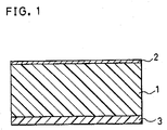
- FIG.1 is a cross-sectional view of a magnetic recording medium of the present invention.
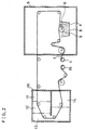
- FIG.2 is a flow diagram showing a gravure coating process for forming a back coat layer.
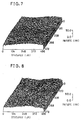
- FIGs. 3, 4, 5, 6, 7 and 8 are enlarged perspective views (with 100 magnification) of the back coat layer of respective Comparison example 8-1, 8-2 and 8-3, Examples 8-1 and 8-2 and Comparison example 8-4 which were obtained by the surface roughness meter.
- FIG.9(a) is an enlarged perspective view (with 100 magnification) of the back coat layer of Example 10-1.
- FIG.8(b) is an enlarged perspective view (with 100 magnification) of the magnetic recording film of Example 10-1.
- FIG.10(a) is an enlarged perspective view (with 100 magnification) of the back coat layer of Comparison example 10-1.
- FIG.10(b) is an enlarged perspective view (with 100 magnification) of the back coat layer of Comparison example 10-1.
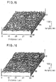
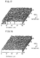
- FIGs. 11, 12, 13, 14, 15, 16, 17 and 18 are enlarged perspective views (with 100 magnification) of the back coat layer of respective Example 12-1, Comparison example 12-1, Comparison example 12-2, Example 12-2, Comparison example 12-3, Example 12-3, Comparison example 12-4 and Example 12-4 which were obtained by the surface roughness meter.
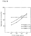
- FIG.19 is a graph showing temperature in respective portions of the drying room as to respective Examples 13-1, 13-2 and 13-3.
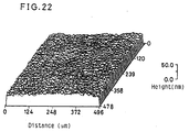
- FIGs. 20, 21 and 22 are enlarged perspective views (with 100 magnification) of the back coat layer of respective Examples 13-1, 13-2 and 13-3 which were obtained by the surface roughness meter.
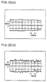
- FIG.23(a) is a wave form of reproduced signal of Example 14-1 observed on the oscilloscope.
- FIG.23(b) is a wave form of reproduced signal of Comparison example 14-1 observed on the oscilloscope.
- FIG. 1 is a cross-sectional view of a magnetic recording medium of the present invention.
- a magnetic recording film 2 is formed on one face of non-magnetic substrate 1
- a back coat layer 3 is formed on opposite face of the non-magnetic substrate 1 to the one face covered by the magnetic recording film 2.
- Suitable film, sheet or the like for the non-magnetic substrate 1 used in the magnetic recording medium of the present invention is made by selecting at least one material from the following known substances: high polymer such as polyamide, polyimide, polysulfone, polycarbonate, polypropylene, polyethylene, polyethlene terephthalate, polyethylene naphthalate, polycellulose acetate, polyvinyl chloride and the like; non-magnetic metal; ceramics such as glass, porcelain and the like.
- Suitable ferromagnetic material for forming the magnetic recording film 2 is as follows: at least one metal selected from Co, Ni and Fe, an alloy thereof with Cr, Mn, Ti, P, Y, Sm, Bi and the like or an alloy with oxidized the same. Among these materials, at least two elements selected from Co, Cr and Ni is preferable for composing the magnetic recording film, since it has high magnetic anisotrophy energy and high saturated magnetization.
- the magnetic recording film is formed by the following known methods: a vapor deposition, a sputtering, an ion plating, a plating or the like.
- the magnetic recording film of the alloy of Co and Cr or oxidized the same is more preferable in actual use owing to its high corrosion resistance.
- the magnetic recording film 2 used in the present invention can be made from other material as mentioned above.
- the back coat layer 3 in the present invention includes the following materials:
- Material for the main agent of polyurethane which has an average molecular weight above 10,000 can be used as binder component. Since thin metal magnetic recording film of Co, Cr or the like has mechanical feature which is different from that of the non-magnetic substrate, it is necessary to select a material for main agent of polyurethane in consideration of suppressions of the following three problems: undesirable curling of the substrate, undesirable transfer of component in the back coat layer onto the magnetic recording film and undesirable transcription of shape of the back coat film surface onto the same. And, suitable material for main agent of polyurethane is a material having high molecular weight and having a glass-transition temperature (hereinafter it is abbreviated to Tg) under the room temperature. And preferable average molecular weight of the material is above 30,000.
- Tg glass-transition temperature
- Preferable Tg is about 10°C. And most preferable average molecular weight of the material is about 50,000 in consideration of Young's modulus, thickness and wear resistance of the back coat film.
- Tg of the whole urethane it is possible to control Tg of the whole urethane by adjusting added amount of low molecular weight polyurethane having high Tg above 60°C to main agent of polyurethane having Tg about 10°C.
- nitrocellulose is added as a mixture of materials of nitrocellulose having different molecular weight.
- a copolymer of nitrocellulose with the other material is also usable.
- a product of isocyanate group having three functional groups which is made of trismethylolpropane and tolylenediisocyanate is usable as a hardener.
- Carbon powder is used to obtain electric conductivity and to improve runability.
- Amount of the carbon powder is controlled to obtain suitable electric conductivity in the range of from 1010 ⁇ /cm2---106 ⁇ /cm2, and the range of the electric conductivity is determined by the metal component used in the magnetic recording film.
- Diameter of the carbon particles in the carbon powder is selected in consideration for easy dispersion in liquid and for effective obtainment of runability.
- the very fine carbon particles (a) have an average particle diameter of about 0.02 ⁇ m and that of coarse carbon particles (b) is larger than about 0.3 ⁇ m.
- carbon particles (c) having different diameter from these carbon particles (a) and (b) for obtaining coarse surface of the back coat layer it is preferable to add carbon particles (c) having different diameter from these carbon particles (a) and (b) for obtaining coarse surface of the back coat layer, and the average particle diameter of the carbon particles (c) is preferably below 1.0 ⁇ m in consideration for thin thickness of the back coat film.
- a surface modification against the carbon powder is effective for improvement of dispersion and runability, and a surface treatment such as a dechlorination is effective for improvement of corrosion resistance. It is possible to use the above-mentioned carbon powder after the surface modification or the surface treatment. These particles after the surface modification or the surface treatment contribute inside hardening of the back coat layer.
- Suitable material for inorganic abrasive pigment is as follows: at least one in the free state selected from aluminum, titatium and silicon, an oxide thereof or a mixture thereof with oxidized cobalt, chromium or iron.
- Suitable material as the inorganic abrasive pigment having suitable diameter is selected out to keep sufficient wear resistance against posts, guides and the like which the back coat layer makes direct contact with in running. Further, the inorganic abrasive pigment has an aim for giving surface glossiness to the back coat layer.
- a material of lubricant is a compound of higher hydrocarbon or a compound of fluoro hydrocarbon, which has a polar group such as fatty acid, salt thereof, ester thereof, amido thereof or alcohol thereof at its end. And it is possible to mix perfluoropolyether in liquid phase only, organic lubricant of molybdenum group only or combination thereof with the above-mentioned compound.
- Amount of the (added) lubricant should be determined in consideration for sufficient dispersion of solution, degree of improvement for runability and undesirable transfer of component in the back coat layer onto the magnetic recording film. And it is preferably less than 1 wt%.
- Suitable first additive is as follows: alkylthiol, alkylamine or silane coupling agent of alkyl group having epoxy group or carboxylic acid, which has a small number of carbon atoms.
- Suitable second additive is a dispersant such as lecithin.
- a thickness of the back coat layer changes according to total thickness of the magnetic recording medium.
- manufacture can be carried out, there is no limitation of thin thickness of the back coat layer as far as influential transcription of shape does not occur.
- the back coat film having a thickness less than 1.0 ⁇ m was suitable in consideration for undesirable transcription of shape.
- the thickness of the back coat film is less than 0.15 ⁇ m, electric conductivity is reduced above 1010 ⁇ /cm2.
- the thickness of the back coat layer is preferably thicker than 0.15 ⁇ m.
- the present invention proposes a method for making a magnetic recording medium having following processes: a process for forming a magnetic thin film on one face of a non-magnetic substrate; and a process for forming a back coat layer on opposite face of the non-magnetic substrate to the one face covered by the magnetic thin film.
- the back coat layer is formed by applying a coating material for the back coat layer including: polyurethane having Tg under the room temperature; isocyanate hardener; carbon powder: inorganic abrasive; and solvent.
- Condition for coating such asincludes types of a gravure roll, rotating speed thereof, pressure of a blade, applying speed, control of temperature for drying and the like, have large influence upon finished surface of the back coat layer.
- Some contrivances made in preparing coating material are selections of suitable proportion of each component of coating material and suitable filtration.
- the coating material has suitable viscosity for coating and brings enough inside hardening of the back coat layer. And effect of elevation of boiling point owing to mixed solvent results in a low volatile coating material.
- the coating material necessitates filtration, wherein it is important to select suitable filter medium and to determine suitable condition of filtration.
- Suitable filter medium should have such a performance (feature) that particles which pass through the filter have an average particle diameter of 0.4 ⁇ m and a maximum diameter of 1.0 ⁇ m.
- suitable condition of filtration is as follows:
- FIG. 2 shows a gravure coating process for forming a back coat layer used in the present invention.
- the gravure coating process has a coating material transfer process and a drying process.
- the coating material transfer process is carried out in a coating room 9, and continuously the drying process is carried out in a drying room 10.
- the non-magnetic substrate whose one face is covered by the magnetic recording film (it is abbreviated to a tape 7) is rolled on a supplying reel 4.
- the tape 7 is fed out and transferred on the gravure roll 5, whereon coating material for the back coat layer 8 is applied on the opposite face of the non- magnetic substrate to the one covered by the magnetic recording film through rotating gravure roll 5.
- a blade 6 holds down the gravure roll 5 as shown by an arrow A for controlling the amount of the coating material which sticks to the surface of the gravure roll 5. That is, a pressure toward the arrow A is applied to the gravure roll 5 by the blade 6, and hereinafter it is abbreviated to a pressure of blade. Immersing depth of gravure roll defined by the part of the gravure roll 5 which is immersed in the coating material 8.
- the drying room 10 is divided into four portions (i.e. first 11, second 12, third 13 and fourth 14). In the actual drying room 10, there was no actual wall or the like for dividing these portions 11, 12, 13 and 14. But in each portion, a set of heater and a controller (including an electric thermometer) therefor is used in order to keep a constant temperature in the portion. The set of a heater and a controller is not shown in FIG.2. And control of temperature for drying is made by setting temperature in each portions. And dried tape 7 is wound up by a winding reel 15.
- the back coat layer has striped pattern and/or thickness of the some becomes unequal and, it does not satisfy the desirable specifics. It is necessary to select such a temperature for drying that minutely finished surface of the back coat layer is obtainable owing to rapid volatility of solvent in hardening process of the back coat layer, as far as there occurs no damage of the magnetic recording film.
- the present invention is applicable to a magnetic recording medium which has a magnetic recording film having a protection layer and/or lubricant layer as a matter of course.
- Table 1 shows results of the evaluation test.
- Example 1-1 embodying the present invention showed smooth runability at 1st transit, and the smooth runability has not been deteriorated even after repeating 50 transits so that it showed improved wear resistance wherein undesirable exfoliation does not occur.
- the magnetic recording medium of the present invention having improved runability was obtained by applying the back coat layer on opposite face of the non-magnetic substrate to the one face covered by the magnetic recording film of Co-Cr, and that the back coat layer includes polyurethane, isocyanate hardening, carbon powder and inorganic abrasive.
- Tg was controlled in the range slightly lower than the room temperature by varying the average molecular weight of the polyurethane, the shape of the magnetic recording medium was apt to become flat. And it is more preferable to use polyurethane having Tg of about 10°C to obtain flatness of the magnetic recording medium.
- the "surface conductivity” was measured by the "four prove method (Baw method)" using a surface conductivity tester type "LORESTA-FP" manufactured by MITSUBISHI PETROCHEMICAL COMPANY. LTD. JAPAN.
- Dynamic frictional coefficient ( ⁇ k ) was measured by a known drawing instrument. A 1m long tape sample was used for measurement under the following condition: tension "P" was 20 gf; and running speed "v” was 8 mm/sec.
- a cylinder load is defined as follows: Video tape sample having 30m length was installed in a VTR cassette, and it was set in an 8 mm system VTR which has a 40mm ⁇ cylinder of aluminum having two pairs of amorphous head (“LAM HEAD") * 1. *1 ) LAM HEAD means Laminated Amorphous Magnetic layer Head.
- the cylinder load was measured by a pen recorder as a voltage meter.
- Table 5 shows results of these evaluation tests as to respective sample tapes.
- Example 3-1 including the carbon particles of an average particle diameter of 0.023 ⁇ m
- Comparison example 3-5 including that of an average particle diameter of 0.014 ⁇ m
- adhesive property of the Comparison example 3-5 was inferior to that of the Example 3-1.
- the Comparison example 3-1 which has relatively thin back coat layer showed unstable runability owing to lowering of wear resistance as shown in large value of the cylinder load.
- the Examples 3-1 and 3-2 showed small number of squares, small dynamic frictional coefficient of about 0.2 and small cylinder load of about 50mV. Thus, improved runability was obtained in these Examples.
- Table shows results of the evaluation test.
- the magnetic recording medium of Example 4-1 shows small dynamic frictional coefficient at 1st transit, and the small dynamic frictional coefficient has not been changed even after repeating 50 transits, so that it showed improved wear resistance wherein undesirable exfoliation does not occur.
- the magnetic recording medium having improved runability was also obtained by applying the back coat layer which includes not only a polyurethane (a) having a Tg under the room temperature but also a polyuretane (b) having a Tg of above 60°C on opposite face of the non-magnetic substrate to the face covered by the magnetic recording film of Co-Cr in comparison with the afore-mentioned Example 1-1.
- the polyurethane (b) has high degree of polymerization.
- a C/Co ratio is defined as a ratio of a mass of C (carbon) with exists on the surface of the magnetic recording film to a mass of Co (cobalt) which exists on the same. It was obtained by quantitative analysis of ESCA (electron spectroscopy for chemical analysis) of C and Co with exist on the magnetic recording film. That is, when transfer of component in the back coat layer onto the magnetic recording film occurs, a mass of C which exists on the surface of the magnetic recording film increases so that the C/Co ratio becomes large. Change of the C/Co ratio obtained after coating of the back coat layer in comparison with that obtained before coating was also shown in Table 8.
- Table 9 shows results of measurement as to sample tapes.
- the magnetic recording medium of Example 6-1 had low ⁇ k and had improved runability. Further, even after repeating 50 transits, ⁇ k changed little, this means that it has an improved wear resistance.
- FIGs. 3---8 are enlarged perspective views (with 100 magnification) of the back coat layer of respective Comparison examples 8-1, 8-2 and 8-3, Examples 8-1 and which were obtained by the surface roughness meter. And measured values of indexes (respective Ra *1, Rms*1 and P-V*1) were also shown in Table 11. *1) These indexes are defined in JIS (Japanese Industrial Standards) B-0601.
- Young's modulus of the tape sample was measured by a Young's modulus meter "TM-7000" (manufactured by SHINKU RIKOU CO LTD. JAPAN).
- condition of dispersion in the coating material and process of hardening would depend on the range of the proportion of components.
- the back coat layer formed by using such suitable range of the proportion of components resulted in improved smoothness, dynamic strength and runability of the magnetic recording medium.
- the back coat layer was formed by using the same material of the Example 8-1.
- the thickness of the back coat layer was 0.6 ⁇ m.
- a 9 ⁇ m thick polyimide film was used as the non-magnetic substrate 1, and a CoCr film was formed as a first magnetic recording layer satisfying specifics shown in a left column of Table 13 and a CoO film was formed as a second magnetic recording layer satisfying specifics shown in a right column of Table 13, on the CoCr film.
- Example 10-1 before applying the coating material for the back coat layer, filtration was made similarly to the Example 9-2. In contrast, in the Comparison example 10-1, no filtration was made.
- FIGs. 9 and 10 are enlarged perspective views (with 100 magnification) of the back coat layer of respective Example 10-1 and Comparison example 10-1
- FIGs. 9(b) and 10(b) are enlarged perspective views (with 100 magnification) of the magnetic recording film of respective Example 10-1 and Comparison example 10-1.
- FIG.10(b) hollow on the surface was observed on the magnetic recording film, and contrary thereto no hollow on the surface was observed in FIG.9(b). That is, flat surface of the magnetic recording film was obtained in Example 10-1.
- the suitable filtration was effective in order to obtain more improved magnetic recording medium having no transfer, no transcription and good runability.
- Example 11-1 and 11-2 and Comparison examples 11-1 and 11-2 only mixing ratio of the hardener was changed.
- Example 11-3 and 11-4 a previous treatment was made on the carbon powder by a silane (group) coupling agent as follows: An ultrasonication was made on the carbon powder for 5 minute in a solution wherein 1 wt % n-octyltriethoxysilane is dissolved in isopropyl alcohol.
- Thickness of the back coat layer was measured by a conventional measuring machine.
- FIGs. 11---18 Surface roughness of the back coat layer was measured by the non-contact type three dimensional surface roughness meter "Type TOPO-3D". The result of measurement was shown in FIGs. 11---18.
- FIGs. 11, 12, 13, 14, 15, 16, 17 and 18 are enlarged perspective view (with 100 magnification of the back coat layer of respective Example 12-1, Comparison example 12-1, Comparison example 12-2, Example 12-2, Comparison example 12-3, Example 12-3.
- Comparison example 12-4 and Example 12-4 which were obtained by the surface roughness meter.
- measured values of indexes (respective Ra *1, Rms*1 and P-V*1) were also shown in Table 15. *1) These indexes are defined in JIS (Japanese Industrial Standards K-0611)
- tape samples which have only the back coat layer and does not have the magnetic recording film were made by the same way as that of Example 12-3 except that: in the STEP(b) the temperature for drying was changed in respective examples as shown in FIG.19.
- the temperature for drying can be controlled by utilizing the guradual drying process shown in FIG.2.
- the drying process was carried out in continuous four portions (i.e. first 11, second 12, third 13 and fourth portion 14) in FIG.2.
- a set of a heater and a controller including an electric thermometer
- the set of a heater and a controller is not shown in FIG.2. And control of temperature for drying is made by setting temperature in each portions. And objective temperature in each four portions of respective Examples 13-1, 13-2 and 13-3 was shown in FIG.19. That is, in Examples 13-1 and 13-2, respective temperature for drying in each portions are set in a manner that temperature becomes gradually high in regular order of portions.
- FIGs. 20, 21 and 22 are enlarged perspective views (with 100 magnification) of the back coat layer of respective Examples 13-1, 13-2 and 13-3.
- the temperature for drying was set gradually in respective four portions from a low temperature about 60°C to a high temperature about 150°C as shown by the Example 13-1 in FIG.19, more solid back coat layer was obtained as shown in FIG.20 in comparison with FIGs. 21 and 22.
- the above-mentioned gradual control of the temperature for drying would mitigate a high evaporation rate of the solvent used in applied coating material.
- Example 14-1 was made by the same procedure as that of Example 1-1 except that:
- the Comparison example 14-1 was made by the same procedure of forming Example 14-1 except that: in the STEP(c): 0.6 ⁇ m thick back coat layer was formed by the same way as that of Comparison example 12-1.
- the back coat layer was made under a bad condition.
- FIG.23(a) shows an observed wave form of the Example 14-1
- FIG.23(b) shows that of the Comparison example 14-1. From FIGs. 23(a) and 23(b), flatness of envelop of the Example 14-1 was more flat than that of the Comparison example 14-1. Thus, the magnetic recording medium having no undesirable transcription suitable for actual use was obtained.
- the back coat layer of the present invention realizes the magnetic recording medium which has the uniform magnetic recording film having wide area and having no transcription of shape.
- the back coat layer of video tape samples was formed by using the same material as that of the Example 8-1.
- a 0.6 ⁇ mm thick back coat layer was formed under a condition shown in Table 17.
- the temperature for drying was set gradually in each portions similar to the Example 13-1, an annealing at 60°C was carried out for 12 hour after drying in order to accelerate hardening.
- the magnetic recording film consisting of two magnetic layer which is the same as that of the Example 14-1.
- Video tape samples of this Example 15-2 were made by the same procedure as that of the Example 15-1 except that: the range of the temperature for drying was changed and no annealing was made as shown in Table 17.
- Video tape samples of this Example 15-3 were made by the same procedure as that of the Example 15-1 except that: the range of the temperature for drying was changed, a condition of annealing was changed and the magnetic recording film consisted of one layer which is as same as the CoO film of the Example 14-1 as shown in Table 17.
- Video tape samples of this Example 15-4 were made by the same procedure as that of the Example 15-1 except that: the range for drying was changed, a condition of annealing was changed and the magnetic recording film consisted of one layer which is as same as the CoCr film of the Example 14-1 as shown in Table 17.
- Video tape samples of this Example 15-5 were made by the same procedure as that of the Example 15-1 except that: the range for drying was changed and no annealing was made as shown in Table 17.
- a C/Co ratio is defined as a ratio of a mass of C (carbon) which exists on the surface of the magnetic recording film to a mass of Co(cobalt) which exists on the same. It was obtained by quantitative analysis of ESCA (electron spectroscopy for chemical analysis) of C and Co which exist on the magnetic recording film. That is, when transfer of component in the back coat layer onto the magnetic recording film occurs, a mass of C which exists on the surface of the magnetic recording film increases so that the C/Co ratio becomes large. Change of the C/Co ratio obtained after coating of the back coat layer in comparison with that obtained before coating was shown in Table 17.
Landscapes
- Paints Or Removers (AREA)
- Magnetic Record Carriers (AREA)
- Manufacturing Of Magnetic Record Carriers (AREA)
Applications Claiming Priority (6)
| Application Number | Priority Date | Filing Date | Title |
|---|---|---|---|
| JP177710/90 | 1990-07-05 | ||
| JP2177710A JPH0464917A (ja) | 1990-07-05 | 1990-07-05 | 磁気記録媒体およびその製造方法 |
| JP2234885A JPH04114314A (ja) | 1990-09-04 | 1990-09-04 | 磁気記録媒体 |
| JP234885/90 | 1990-09-04 | ||
| JP3010639A JPH04245022A (ja) | 1991-01-31 | 1991-01-31 | 磁気記録媒体の製造方法 |
| JP10639/91 | 1991-01-31 |
Publications (3)
| Publication Number | Publication Date |
|---|---|
| EP0464827A2 true EP0464827A2 (fr) | 1992-01-08 |
| EP0464827A3 EP0464827A3 (en) | 1992-03-18 |
| EP0464827B1 EP0464827B1 (fr) | 1995-04-19 |
Family
ID=27279034
Family Applications (1)
| Application Number | Title | Priority Date | Filing Date |
|---|---|---|---|
| EP91111149A Expired - Lifetime EP0464827B1 (fr) | 1990-07-05 | 1991-07-04 | Support d'enregistrement magnétique et sa méthode de fabrication |
Country Status (4)
| Country | Link |
|---|---|
| US (1) | US5433999A (fr) |
| EP (1) | EP0464827B1 (fr) |
| KR (1) | KR960008547B1 (fr) |
| DE (1) | DE69108996T2 (fr) |
Cited By (6)
| Publication number | Priority date | Publication date | Assignee | Title |
|---|---|---|---|---|
| WO1993016466A1 (fr) * | 1992-02-10 | 1993-08-19 | Minnesota Mining And Manufacturing Company | Support d'enregistrement magnetique dote sur sa face arriere d'un revetement rugueux derive de copolymeres en blocs |
| WO1993024924A3 (fr) * | 1992-06-04 | 1994-02-03 | Minnesota Mining & Mfg | Support d'enregistrement magnetique comprenant un agent de liaison qui peut etre durci a la fois par des techniques de durcissement a l'isocyanate et par rayonnement |
| WO1994011866A1 (fr) * | 1992-11-06 | 1994-05-26 | Minnesota Mining And Manufacturing Company | Revetement de la face arriere d'un support d'enregistrement magnetique |
| WO1996000440A1 (fr) * | 1994-06-23 | 1996-01-04 | Imperial Chemical Industries Plc | Support d'enregistrement |
| FR2722026A1 (fr) * | 1994-06-30 | 1996-01-05 | Sony Corp | Support d'enregistrement magnetique |
| US5487951A (en) * | 1991-07-08 | 1996-01-30 | Minnesota Mining And Manufacturing Company | Magnetic recording medium with a binder resin of a starblock copolymer having at least six arms |
Family Cites Families (9)
| Publication number | Priority date | Publication date | Assignee | Title |
|---|---|---|---|---|
| US4328935A (en) * | 1980-06-12 | 1982-05-11 | Minnesota Mining And Manufacturing Company | Flexible magnetic recording tape having low-friction backside coating |
| JPS59210534A (ja) * | 1983-05-16 | 1984-11-29 | Fuji Photo Film Co Ltd | 磁気記録媒体 |
| JPS60136913A (ja) * | 1983-12-26 | 1985-07-20 | Konishiroku Photo Ind Co Ltd | 磁気記録媒体 |
| JPS62146433A (ja) * | 1985-12-20 | 1987-06-30 | Fuji Photo Film Co Ltd | 磁気記録媒体 |
| JPH0644345B2 (ja) * | 1987-04-30 | 1994-06-08 | 富士写真フイルム株式会社 | 磁気記録媒体の製造方法 |
| US5055349A (en) * | 1987-10-16 | 1991-10-08 | Konica Corporation | Magnetic recording medium |
| JPH01173420A (ja) * | 1987-12-28 | 1989-07-10 | Konica Corp | 非磁性粉を含有するバックコート層を設けた磁気記録媒体 |
| NL8802178A (nl) * | 1988-09-02 | 1990-04-02 | Stichting Tech Wetenschapp | Prothetische voortbrengsels met botbindende eigenschappen. |
| JP2850028B2 (ja) * | 1989-12-28 | 1999-01-27 | コニカ株式会社 | 磁気記録媒体 |
-
1991
- 1991-07-04 DE DE69108996T patent/DE69108996T2/de not_active Expired - Fee Related
- 1991-07-04 EP EP91111149A patent/EP0464827B1/fr not_active Expired - Lifetime
- 1991-07-05 KR KR1019910011378A patent/KR960008547B1/ko not_active Expired - Fee Related
-
1993
- 1993-09-29 US US08/128,075 patent/US5433999A/en not_active Expired - Fee Related
Cited By (6)
| Publication number | Priority date | Publication date | Assignee | Title |
|---|---|---|---|---|
| US5487951A (en) * | 1991-07-08 | 1996-01-30 | Minnesota Mining And Manufacturing Company | Magnetic recording medium with a binder resin of a starblock copolymer having at least six arms |
| WO1993016466A1 (fr) * | 1992-02-10 | 1993-08-19 | Minnesota Mining And Manufacturing Company | Support d'enregistrement magnetique dote sur sa face arriere d'un revetement rugueux derive de copolymeres en blocs |
| WO1993024924A3 (fr) * | 1992-06-04 | 1994-02-03 | Minnesota Mining & Mfg | Support d'enregistrement magnetique comprenant un agent de liaison qui peut etre durci a la fois par des techniques de durcissement a l'isocyanate et par rayonnement |
| WO1994011866A1 (fr) * | 1992-11-06 | 1994-05-26 | Minnesota Mining And Manufacturing Company | Revetement de la face arriere d'un support d'enregistrement magnetique |
| WO1996000440A1 (fr) * | 1994-06-23 | 1996-01-04 | Imperial Chemical Industries Plc | Support d'enregistrement |
| FR2722026A1 (fr) * | 1994-06-30 | 1996-01-05 | Sony Corp | Support d'enregistrement magnetique |
Also Published As
| Publication number | Publication date |
|---|---|
| US5433999A (en) | 1995-07-18 |
| DE69108996T2 (de) | 1995-08-31 |
| DE69108996D1 (de) | 1995-05-24 |
| KR960008547B1 (ko) | 1996-06-28 |
| KR920003266A (ko) | 1992-02-29 |
| EP0464827B1 (fr) | 1995-04-19 |
| EP0464827A3 (en) | 1992-03-18 |
Similar Documents
| Publication | Publication Date | Title |
|---|---|---|
| US6207252B1 (en) | Magnetic recording medium and production method thereof | |
| EP0392810B1 (fr) | Milieu d'enregistrement magnétique | |
| EP0464827B1 (fr) | Support d'enregistrement magnétique et sa méthode de fabrication | |
| JPH0547888B2 (fr) | ||
| US5084336A (en) | Magnetic recording medium | |
| JP2670834B2 (ja) | 磁気記録媒体の製造方法及び装置 | |
| JP3355791B2 (ja) | 磁気記録媒体 | |
| US5786093A (en) | Magnetic recording medium having a backcoat composition with low chloride ion and sulfate ion extractables | |
| US6235368B1 (en) | Magnetic recording medium having a high recording density and its production | |
| EP0911814A2 (fr) | Support d'enregistrement magnétique | |
| JPH1173629A (ja) | 磁気記録媒体 | |
| JP2855440B2 (ja) | 磁気記録媒体 | |
| KR100304013B1 (ko) | 자기기록매체의제조방법 | |
| JPS6262420A (ja) | 磁気記録媒体 | |
| JPS62197925A (ja) | バツクコ−ト層を有する磁気記録媒体 | |
| JPH05274652A (ja) | 磁気記録媒体及び該磁気記録媒体を装填した磁気テープカセット | |
| JPH04251427A (ja) | 磁気記録媒体 | |
| JP2802769B2 (ja) | 磁気記録媒体の製造方法 | |
| JPS6391824A (ja) | 磁気記録媒体 | |
| JPH0481262B2 (fr) | ||
| JP2001266332A (ja) | 磁気記録媒体 | |
| JPS62124627A (ja) | 磁気記録媒体 | |
| JPS6273421A (ja) | 磁気記録媒体 | |
| JPH01173426A (ja) | 非磁性粉を含有するバックコート層を設けた磁気記録媒体 | |
| JPS61177626A (ja) | 磁気記録媒体 |
Legal Events
| Date | Code | Title | Description |
|---|---|---|---|
| PUAI | Public reference made under article 153(3) epc to a published international application that has entered the european phase |
Free format text: ORIGINAL CODE: 0009012 |
|
| 17P | Request for examination filed |
Effective date: 19910704 |
|
| AK | Designated contracting states |
Kind code of ref document: A2 Designated state(s): DE FR GB |
|
| PUAL | Search report despatched |
Free format text: ORIGINAL CODE: 0009013 |
|
| AK | Designated contracting states |
Kind code of ref document: A3 Designated state(s): DE FR GB |
|
| 17Q | First examination report despatched |
Effective date: 19930419 |
|
| GRAA | (expected) grant |
Free format text: ORIGINAL CODE: 0009210 |
|
| AK | Designated contracting states |
Kind code of ref document: B1 Designated state(s): DE FR GB |
|
| ET | Fr: translation filed | ||
| REF | Corresponds to: |
Ref document number: 69108996 Country of ref document: DE Date of ref document: 19950524 |
|
| PLBE | No opposition filed within time limit |
Free format text: ORIGINAL CODE: 0009261 |
|
| STAA | Information on the status of an ep patent application or granted ep patent |
Free format text: STATUS: NO OPPOSITION FILED WITHIN TIME LIMIT |
|
| 26N | No opposition filed | ||
| REG | Reference to a national code |
Ref country code: GB Ref legal event code: IF02 |
|
| PGFP | Annual fee paid to national office [announced via postgrant information from national office to epo] |
Ref country code: GB Payment date: 20050629 Year of fee payment: 15 |
|
| PGFP | Annual fee paid to national office [announced via postgrant information from national office to epo] |
Ref country code: DE Payment date: 20050630 Year of fee payment: 15 |
|
| PGFP | Annual fee paid to national office [announced via postgrant information from national office to epo] |
Ref country code: FR Payment date: 20050708 Year of fee payment: 15 |
|
| PG25 | Lapsed in a contracting state [announced via postgrant information from national office to epo] |
Ref country code: GB Free format text: LAPSE BECAUSE OF NON-PAYMENT OF DUE FEES Effective date: 20060704 |
|
| PG25 | Lapsed in a contracting state [announced via postgrant information from national office to epo] |
Ref country code: DE Free format text: LAPSE BECAUSE OF NON-PAYMENT OF DUE FEES Effective date: 20070201 |
|
| GBPC | Gb: european patent ceased through non-payment of renewal fee |
Effective date: 20060704 |
|
| REG | Reference to a national code |
Ref country code: FR Ref legal event code: ST Effective date: 20070330 |
|
| PG25 | Lapsed in a contracting state [announced via postgrant information from national office to epo] |
Ref country code: FR Free format text: LAPSE BECAUSE OF NON-PAYMENT OF DUE FEES Effective date: 20060731 |