EP0465268B1 - Metalldichtung - Google Patents
Metalldichtung Download PDFInfo
- Publication number
- EP0465268B1 EP0465268B1 EP91306142A EP91306142A EP0465268B1 EP 0465268 B1 EP0465268 B1 EP 0465268B1 EP 91306142 A EP91306142 A EP 91306142A EP 91306142 A EP91306142 A EP 91306142A EP 0465268 B1 EP0465268 B1 EP 0465268B1
- Authority
- EP
- European Patent Office
- Prior art keywords
- cylinder
- gasket
- metallic gasket
- stoppers
- base plates
- Prior art date
- Legal status (The legal status is an assumption and is not a legal conclusion. Google has not performed a legal analysis and makes no representation as to the accuracy of the status listed.)
- Expired - Lifetime
Links
- 239000011324 bead Substances 0.000 claims description 39
- 238000002485 combustion reaction Methods 0.000 claims description 14
- 239000002184 metal Substances 0.000 claims description 4
- 229910052751 metal Inorganic materials 0.000 claims description 4
- 230000002093 peripheral effect Effects 0.000 claims description 3
- 238000010276 construction Methods 0.000 description 8
- 238000007789 sealing Methods 0.000 description 6
- 238000010285 flame spraying Methods 0.000 description 3
- PXHVJJICTQNCMI-UHFFFAOYSA-N Nickel Chemical compound [Ni] PXHVJJICTQNCMI-UHFFFAOYSA-N 0.000 description 2
- 239000000567 combustion gas Substances 0.000 description 2
- 239000000498 cooling water Substances 0.000 description 2
- 238000006073 displacement reaction Methods 0.000 description 2
- 239000007769 metal material Substances 0.000 description 2
- 239000011148 porous material Substances 0.000 description 2
- RYGMFSIKBFXOCR-UHFFFAOYSA-N Copper Chemical compound [Cu] RYGMFSIKBFXOCR-UHFFFAOYSA-N 0.000 description 1
- HCHKCACWOHOZIP-UHFFFAOYSA-N Zinc Chemical compound [Zn] HCHKCACWOHOZIP-UHFFFAOYSA-N 0.000 description 1
- 239000000956 alloy Substances 0.000 description 1
- 229910045601 alloy Inorganic materials 0.000 description 1
- 229910052802 copper Inorganic materials 0.000 description 1
- 239000010949 copper Substances 0.000 description 1
- 230000000694 effects Effects 0.000 description 1
- 239000013013 elastic material Substances 0.000 description 1
- 239000010687 lubricating oil Substances 0.000 description 1
- 150000002739 metals Chemical class 0.000 description 1
- 229910052759 nickel Inorganic materials 0.000 description 1
- 239000003921 oil Substances 0.000 description 1
- 238000007747 plating Methods 0.000 description 1
- 239000012858 resilient material Substances 0.000 description 1
- 229910052725 zinc Inorganic materials 0.000 description 1
- 239000011701 zinc Substances 0.000 description 1
Images

Classifications
-
- F—MECHANICAL ENGINEERING; LIGHTING; HEATING; WEAPONS; BLASTING
- F16—ENGINEERING ELEMENTS AND UNITS; GENERAL MEASURES FOR PRODUCING AND MAINTAINING EFFECTIVE FUNCTIONING OF MACHINES OR INSTALLATIONS; THERMAL INSULATION IN GENERAL
- F16J—PISTONS; CYLINDERS; SEALINGS
- F16J15/00—Sealings
- F16J15/02—Sealings between relatively-stationary surfaces
- F16J15/06—Sealings between relatively-stationary surfaces with solid packing compressed between sealing surfaces
- F16J15/08—Sealings between relatively-stationary surfaces with solid packing compressed between sealing surfaces with exclusively metal packing
- F16J15/0818—Flat gaskets
- F16J15/0825—Flat gaskets laminated
-
- F—MECHANICAL ENGINEERING; LIGHTING; HEATING; WEAPONS; BLASTING
- F02—COMBUSTION ENGINES; HOT-GAS OR COMBUSTION-PRODUCT ENGINE PLANTS
- F02F—CYLINDERS, PISTONS OR CASINGS, FOR COMBUSTION ENGINES; ARRANGEMENTS OF SEALINGS IN COMBUSTION ENGINES
- F02F11/00—Arrangements of sealings in combustion engines
- F02F11/002—Arrangements of sealings in combustion engines involving cylinder heads
-
- F—MECHANICAL ENGINEERING; LIGHTING; HEATING; WEAPONS; BLASTING
- F16—ENGINEERING ELEMENTS AND UNITS; GENERAL MEASURES FOR PRODUCING AND MAINTAINING EFFECTIVE FUNCTIONING OF MACHINES OR INSTALLATIONS; THERMAL INSULATION IN GENERAL
- F16J—PISTONS; CYLINDERS; SEALINGS
- F16J15/00—Sealings
- F16J15/02—Sealings between relatively-stationary surfaces
- F16J15/06—Sealings between relatively-stationary surfaces with solid packing compressed between sealing surfaces
- F16J15/08—Sealings between relatively-stationary surfaces with solid packing compressed between sealing surfaces with exclusively metal packing
- F16J15/0818—Flat gaskets
- F16J2015/0837—Flat gaskets with an edge portion folded over a second plate or shim
-
- F—MECHANICAL ENGINEERING; LIGHTING; HEATING; WEAPONS; BLASTING
- F16—ENGINEERING ELEMENTS AND UNITS; GENERAL MEASURES FOR PRODUCING AND MAINTAINING EFFECTIVE FUNCTIONING OF MACHINES OR INSTALLATIONS; THERMAL INSULATION IN GENERAL
- F16J—PISTONS; CYLINDERS; SEALINGS
- F16J15/00—Sealings
- F16J15/02—Sealings between relatively-stationary surfaces
- F16J15/06—Sealings between relatively-stationary surfaces with solid packing compressed between sealing surfaces
- F16J15/08—Sealings between relatively-stationary surfaces with solid packing compressed between sealing surfaces with exclusively metal packing
- F16J15/0818—Flat gaskets
- F16J2015/085—Flat gaskets without fold over
Definitions
- the present invention relates to metallic gaskets designed to be interposed between the joining surfaces of a cylinder head and a cylinder block which form part of an internal combustion engine, thereby preventing leakages of combustion gas, cooling water, lubricating oil, etc.
- an array of beads are located concentrically with a combustion chamber bore formed in an elastic base plate of a metallic gasket. As the metallic gasket is clamped in place by means of bolts, the beads produce repulsive force, which is in turn used to impart a sealing function to the peripheral edge of the combustion chamber.
- stoppers are located on flat segments of the metallic gasket between the combustion chamber bore and the beads, thereby limiting the magnitude of amplitude of the beads so as to prevent their complete yielding.
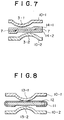
- FIG. 8 A prior proposed such arrangement (see EP-A-0 230 804) is shown in Fig. 8 in a sectional view showing only an inter-cylinder part for the purpose of simplicity.
- Reference numerals 10-1 and 10-2 stand for base plates, each formed of a resilient material. While an auxiliary plate 12 covered with a shim plate 11 is sandwiched between the base plates, arched beads 13-1 and 13-2 are symmetrically located thereon in opposite relation. The shim plate 11 is then folded down at both its ends to form bends serving as stoppers. These bends limit the amplitude of vibration of the beads.
- a metallic gasket adapted to be interposed between cylinder head and cylinder block in a multi-cylindered internal combustion engine, the gasket having an opening corresponding to each combustion chamber of the cylinder block, the gasket comprising two base plates formed of resilient metal, and each combustion chamber gasket opening having beads adjacent the peripheral edge thereof; the gasket being characterised in that one of said base plates is provided with an array of arched beads which are associated with odd-numbered cylinders, in that the other base plate is provided with an array of arched beads which are associated with even-numbered cylinders, in that, for any inter-cylinder space separating an odd-numbered cylinder from an even-numbered cylinder, the bead associated with the odd-numbered cylinder is displaced from the centre of the inter-cylinder space in one direction to define a flat for a stopper, and the bead associated with the even-numbered cylinder is displaced in the opposite direction also to define a flat for a stopper, and in that said base plates are laminated antisymmetrically with
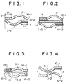
- Figure 1 is a sectional view illustrative of one embodiment of the metallic gasket for a multi-cylindered arrangement as it would be seen taken along a section corresponding to the line A-A′ of Figure 5.
- a metallic gasket body shown at 1 includes a base plate 10 made of an elastic material.
- the base plate 10 is constructed from upper and lower plates 10-1 and 10-2, and has openings 2 located in association with combustion chamber bores, and each provided at its edge with a bead 3, as will be described later.
- reference numeral 4 indicates a bolt hole through which a bolt or screw is inserted to fix the metallic gasket in place when it is built in an engine, 5 a hole through which cooling water circulates, and 6 an oil hole.
- the metallic gasket is basically constructed from two upper and lower plates 10-1 and 10-2.
- One plate 10-1 in Figure 1 is provided with an arched bead 3-1 which is associated with an odd-numbered cylinder and displaced righthandedly from the centre of the inter-cylinder space L between the said cylinder and the next adjacent cylinder to define a flat segment L1 on the left side.
- a stopper 7 is attached to this flat segment.
- the other base plate 10-2 is provided with an arched bead 3-2, which is associated with an even-numbered cylinder and displaced lefthandedly from the centre of the inter-cylinder space L to define a flat segment L1 in the opposite or right side.
- a stopper 7 is attached to this flat segment L1.
- the upper and lower base plates 10-1 and 10-2 are alternately provided with the stoppers.
- the bead 3-1 on the base plate 10-1 is located on the outer edge of a cylinder #1 with the bead location being somewhat shifted toward a cylinder #2, not lying at the centre of the inter-cylinder space L. Consequently, a flat segment L1 is defined at the left end of the inter-cylinder space L to receive the stopper 7.
- the bead 3-1 on the base plate 10-2 is located on the outer edge of the cylinder #2 and, contrary to the above-mentioned bead 3-1, is shifted toward the cylinder #1. Consequently, the flat segment L1 is defined at the right end of the inter-cylinder space L to receive the associated stopper 7.
- the base plates 10-1 and 10-2 are laminated together antisymmetrically with respect to the bead locations.
- the arched beads are displaced with respect to each other in a limited space between the adjacent cylinders, enabling flat segments to be defined on the opposite sides.
- the flat segment is defined on the left side of the base plate 10-1 on which the bead 3-1 is located righthandedly, while the flat segment is defined on the right side fo the base plate 10-2 on which the bead 3-2 is located lefthandedly.
- the inter-cylinder space L needed to be at least 5 mm in order to leave stopper locations, each of 1.5 mm in width, at both sides of each bead.
- the base plates may be formed of springy SUS 301 or SUS 304 (JIS), with a thickness lying in the range of 0.20 to 0.30 mm.
- the stoppers may be formed of an alloy consisting of, e.g., 20% of nickel and 20% or zinc and 60% of copper by flame spraying, with a thickness lying in the range of 0.5 to 0.15 mm.
- FIG 2 illustrates the construction of another embodiment of metallic gasket also according to this invention.
- the same parts as in Figure 1 are indicated by the same reference numerals and so will be not explained.
- an auxiliary plate 14 is sandwiched between base plates 10-1 and 10-2, each having an arched bead on its outside.
- This embodiment is applicable to an engine including a close array of cylinders.
- the auxiliary plate 14 may be formed of SUS 304 or JIS SPC with a thickness lying in the range of 0.3 to 1.5 mm.
- Figure 3 illustrates the construction of a further embodiment of metallic gasket according to this invention.
- a shim plate 15 is inserted beween base plates 10-1 and 10-2 and is folded up and down at its ends to form folds 15-1 and 15-2 serving as stoppers. Even with this embodiment, stopper locations of sufficient width are achievable.
- the shim plate may be formed of SUS 304 or SUS 301 with a thickness lying usually in the range of 0.08 to 0.15 mm.
- Figure 4 shows the construction of a still further embodiment of metallic gasket according to this invention.
- the apices of arched beads 3-1 and 3-2 are displaced from each other, while they are located oppositely to each other, forming diagonally located flat segments on the inside of the base plates, on which stoppers 7 are provided.
- stopper locations not only are stopper locations ensured, but also an increased pressure may be obtained on the metallic gasket between the cylinders. This is because one bead engages another associated bead adjacent its apex, thereby increasing the spring constant at the bead locations.
- Figure 6 shows the construction of a still further embodiment of the metallic gasket according to this invention, Figure 6(a) being a sectional view taken along the line A-A′ of Fighure 5 and Figure 6(b) a sectional view taken along the line B-B′ of Figure 5.
- an auxiliary plate 14 is sandwiched between base plates 10-1 and 10-2, each having an arched bead 3-1 or 3-2 on its inside. Stoppers 7 are then provided on the auxiliary plate 14. Even with this embodiment, effects similar to those already mentioned are achievable.
- Figure 7 shows the construction of a still further embodiment of metallic gasket according to this invention.
- an auxiliary plate is divided into two parts 14-1 and 14-2, between which stoppers are interposed. It is noted that when the stoppers are formed of a porous material by flame spraying, the pores need not be filled because of being covered with the parts 14-1 and 14-2.
- This embodiment employs a two-part sealing achieved by both the stoppers and the beads, obtaining further improvement in sealing performance.
- the stoppers may be formed of metals by flame spraying or plating, made of flat metal materials or moulded of metal materials.
Landscapes
- Engineering & Computer Science (AREA)
- General Engineering & Computer Science (AREA)
- Mechanical Engineering (AREA)
- Chemical & Material Sciences (AREA)
- Combustion & Propulsion (AREA)
- Gasket Seals (AREA)
Claims (5)
- Metallische Dichtung, geeignet zum Einsetzen zwischen Zylinderkopf und Zylinderblock in einer mehrzylindrigen Brennkraftmaschine, wobei die Dichtung eine Öffnung (2) entsprechend zu jeder Brennkammer des Zylinderblocks aufweist, die Dichtung zwei Grundplatten (10-1, 10-2) aus elastischem Metall umfaßt und jede Brennkammerdichtungsöffnung Sicken (3-1,3-2) benachbart zum Randbereich hiervon aufweist, wobei die Dichtung dadurch gekennzeichnet ist, daß eine (10-1) der besagten Grundplatten mit einer Reihe von gewölbten Sicken (3-1) versehen ist, die ungeradzahligen Zylindern (#1,#3) zugeordnet sind, daß die andere Grundplatte (10-2) mit einer Reihe von gewölbten Sicken (3-2) versehen ist, die geradzahligen Zylindern (#2) zugeordnet sind, daß für jeden Zwischenzylinderraum (L), der ungeradzahlige Zylinder von einem geradzahligen Zylinder trennt, die Sicke (3-1), die dem ungeradzahligen Zylinder zugeordnet ist, von der Mitte des Zwischenzylinderraums (L) in einer Richtung versetzt ist, um eine Fläche für einen Stopper (7) zu definieren, und die Sicke (3-2), die dem geradzahligen Zylinder zugeordnet ist, in entgegengesetzter Richtung versetzt ist, um ebenfalls eine Fläche für einen Stopper (7) zu bilden, und daß besagte Grundplatten (10-1,10-2) antisymmetrisch zueinander geschichtet sind.
- Metallische Dichtung, wie in Anspruch 1 beansprucht, weiter dadurch gekennzeichnet, daß besagte Stopper durch Umfalzen eines Endes (15-1) einer Einlegeplatte (15) nach oben und des anderen Endes (15-2) nach unten gebildet sind, die zwischen besagten Grundplatten eingelegt ist.
- Metallische Dichtung, wie in Anspruch 1 beansprucht, weiter dadurch gekennzeichnet, daß besagte Stopper (7) auf entsprechenden oberen und unteren Abschnitten einer Hilfsplatte (14) vorgesehen sind, die zwischen besagten Grundplatten eingelegt ist.
- Metallische Dichtung, wie in Anspruch 1 beansprucht, weiter dadurch gekennzeichnet, daß eine Hilfsplatte in zwei Teile (14-1,14-2), zwischen denen die Stopper (7) angeordnet sind, unterteilt ist.
- Metallische Dichtung, wie in Anspruch 2, 3 oder 4 beansprucht, weiter dadurch gekennzeichnet, daß besagte Stopper (7) in ihrer Stärke variieren.
Applications Claiming Priority (4)
| Application Number | Priority Date | Filing Date | Title |
|---|---|---|---|
| JP178423/90 | 1990-07-05 | ||
| JP17842390 | 1990-07-05 | ||
| JP3147780A JP2691805B2 (ja) | 1990-07-05 | 1991-05-23 | 多気筒金属ガスケット |
| JP147780/91 | 1991-05-23 |
Publications (2)
| Publication Number | Publication Date |
|---|---|
| EP0465268A1 EP0465268A1 (de) | 1992-01-08 |
| EP0465268B1 true EP0465268B1 (de) | 1994-12-07 |
Family
ID=26478226
Family Applications (1)
| Application Number | Title | Priority Date | Filing Date |
|---|---|---|---|
| EP91306142A Expired - Lifetime EP0465268B1 (de) | 1990-07-05 | 1991-07-05 | Metalldichtung |
Country Status (4)
| Country | Link |
|---|---|
| US (1) | US5197747A (de) |
| EP (1) | EP0465268B1 (de) |
| JP (1) | JP2691805B2 (de) |
| DE (1) | DE69105643T2 (de) |
Families Citing this family (26)
| Publication number | Priority date | Publication date | Assignee | Title |
|---|---|---|---|---|
| EP0468526B1 (de) * | 1990-07-26 | 1995-04-05 | Taiho Kogyo Co., Ltd. | Metalldichtung |
| JPH087170Y2 (ja) * | 1992-02-18 | 1996-03-04 | 石川ガスケット株式会社 | 金属積層形ガスケットのハーフビード |
| DE4305974C1 (de) * | 1993-02-26 | 1994-05-05 | Klinger Ag Zug | Metallische Flachdichtung |
| JP3581162B2 (ja) * | 1993-07-07 | 2004-10-27 | 日本リークレス工業株式会社 | 金属ガスケットの製造方法 |
| GB9408233D0 (en) * | 1994-04-26 | 1994-06-15 | T & N Technology Ltd | Gasket having a compression stop |
| DE4425669C2 (de) * | 1994-07-20 | 1998-02-26 | Payen Goetze Gmbh | Metallische Zylinderkopfdichtung |
| DE4440503C1 (de) * | 1994-11-12 | 1996-03-28 | Payen Goetze Gmbh | Metallische Flachdichtung |
| DE19528031A1 (de) * | 1995-07-31 | 1997-02-06 | Krebsoege Sinterholding Gmbh | Flachdichtung aus Metall |
| DE19625491C1 (de) * | 1996-06-26 | 1997-10-02 | Payen Goetze Gmbh | Metallische Flachdichtung |
| US5695203A (en) * | 1996-09-30 | 1997-12-09 | Ishikawa Gasket Co., Ltd. | Metal gasket with coating layer |
| DE19719328C1 (de) * | 1997-05-08 | 1998-06-25 | Elringklinger Gmbh | Metallische Zylinderkopfdichtung |
| DE19749054C2 (de) * | 1997-11-06 | 1999-10-07 | Federal Mogul Sealing Sys Spa | Metallische Flachichtung |
| DE19749053C2 (de) * | 1997-11-06 | 1999-09-30 | Federal Mogul Sealing Sys Spa | Metallische Zylinderkopfdichtung |
| US6113109A (en) * | 1998-04-20 | 2000-09-05 | Fel-Pro Incorporated | Expanded graphite gasket with beaded stress risers |
| JP3419447B2 (ja) * | 2000-08-07 | 2003-06-23 | 石川ガスケット株式会社 | ヘッドガスケット |
| JP3709365B2 (ja) * | 2001-10-23 | 2005-10-26 | 石川ガスケット株式会社 | メタルガスケット |
| JP2003130224A (ja) * | 2001-10-23 | 2003-05-08 | Ishikawa Gasket Co Ltd | メタルガスケット |
| US7017918B2 (en) * | 2001-10-25 | 2006-03-28 | Federal-Mogul World Wide, Inc. | Combustion stopper seal |
| JP2005201329A (ja) * | 2004-01-14 | 2005-07-28 | Nippon Leakless Corp | シリンダーヘッド用メタルガスケット |
| US7374177B2 (en) * | 2004-09-21 | 2008-05-20 | Federal-Mogul World Wide, Inc. | Enhanced multilayer metal gasket |
| WO2011022530A2 (en) | 2009-08-19 | 2011-02-24 | Federal-Mogul Corporation | Cylinder head gasket assembly |
| WO2011103373A1 (en) * | 2010-02-19 | 2011-08-25 | Federal-Mogul Corporation | Multilayer gasket with labyrinth stopper |
| DE102010039681B4 (de) * | 2010-08-24 | 2014-07-10 | Federal-Mogul Sealing Systems Gmbh | Verfahren zur Herstellung eines Flachbauteiles mit mindestens einem Funktionselement und mit dem Verfahren hergestelltes Flachbauteil |
| US12416359B2 (en) | 2018-08-01 | 2025-09-16 | Federal-Mogul Motorparts Llc | Self-forming gasket assembly and methods of construction and assembly thereof |
| KR20200065743A (ko) * | 2018-11-30 | 2020-06-09 | 현대자동차주식회사 | 터보차저 체결구조 |
| CN112012845A (zh) * | 2019-05-29 | 2020-12-01 | 东亚工业株式会社 | 具有多层止动结构的气缸盖垫片 |
Family Cites Families (25)
| Publication number | Priority date | Publication date | Assignee | Title |
|---|---|---|---|---|
| US2197916A (en) * | 1937-01-27 | 1940-04-23 | Detroit Gasket & Mfg Company | Gasket |
| US3668036A (en) * | 1970-01-26 | 1972-06-06 | Farnam Co F D | Method for attaching gasket and/or insulator members to plate structures |
| GB2063386B (en) * | 1979-11-23 | 1983-04-13 | Nicholson T P | Gaskets |
| US4428593A (en) * | 1981-07-10 | 1984-01-31 | Felt Products Mfg. Co. | Gasket assembly having improved sealing characteristics and method of making same |
| JPS62155374A (ja) * | 1985-12-27 | 1987-07-10 | Nippon Metal Gasket Kk | 金属ガスケツト |
| JPS60160549A (ja) * | 1984-01-31 | 1985-08-22 | Nec Kagoshima Ltd | 螢光表示管 |
| JPS61103668A (ja) * | 1984-10-25 | 1986-05-22 | Mitsubishi Heavy Ind Ltd | 複合ロ−ル製造装置 |
| JPS6288877A (ja) * | 1985-10-11 | 1987-04-23 | Hamamatsu Gasket Seisakusho:Kk | 金属ガスケツト |
| JPH0231632Y2 (de) * | 1985-10-12 | 1990-08-27 | ||
| CA1289159C (en) * | 1985-12-27 | 1991-09-17 | Nobuo Yoshino | Metallic gasket |
| JPS62155375A (ja) * | 1985-12-27 | 1987-07-10 | Nippon Metal Gasket Kk | 金属ガスケツト |
| JPH0622135Y2 (ja) * | 1986-01-13 | 1994-06-08 | 石川ガスケット株式会社 | 金属積叢形マニホ−ルドガスケット |
| JPS62261761A (ja) * | 1986-04-16 | 1987-11-13 | Nippon Metal Gasket Kk | 積層金属ガスケツト |
| JPS63210464A (ja) * | 1987-02-25 | 1988-09-01 | Nippon Metal Gasket Kk | 積層金属ガスケツト |
| JP2523321B2 (ja) * | 1987-05-27 | 1996-08-07 | 日本メタルガスケット株式会社 | 積層金属ガスケット |
| US4759585A (en) * | 1987-06-26 | 1988-07-26 | Ishikawa Gasket Co., Ltd. | Steel laminate gasket with meshing corrugated beads |
| DE3869877D1 (de) * | 1987-09-05 | 1992-05-14 | Nihon Metal Gasket | Laminierte metalldichtung. |
| JPS6479471A (en) * | 1987-09-18 | 1989-03-24 | Nihon Metal Gasket | Laminated metal gasket |
| JPS6483843A (en) * | 1987-09-24 | 1989-03-29 | Kuniaki Numaya | Metal gasket |
| JP2560046B2 (ja) * | 1987-10-15 | 1996-12-04 | 日本メタルガスケット株式会社 | 金属ガスケット |
| JPH01182563A (ja) * | 1988-01-14 | 1989-07-20 | Kuniaki Numaya | メタルガスケット |
| JPH01285644A (ja) * | 1988-05-07 | 1989-11-16 | Nippon Gasket Kk | シリンダーヘッドの金属ガスケット |
| JPH01285645A (ja) * | 1988-05-07 | 1989-11-16 | Nippon Gasket Kk | シリンダーヘッドの金属ガスケット |
| US4898396A (en) * | 1988-08-11 | 1990-02-06 | Ishikawa Gasket Co., Ltd. | Steel laminate gasket |
| JP3057559U (ja) * | 1998-09-07 | 1999-06-02 | 株式会社ならや本舗 | 筆先調整具 |
-
1991
- 1991-05-23 JP JP3147780A patent/JP2691805B2/ja not_active Expired - Fee Related
- 1991-07-05 DE DE69105643T patent/DE69105643T2/de not_active Expired - Lifetime
- 1991-07-05 EP EP91306142A patent/EP0465268B1/de not_active Expired - Lifetime
- 1991-07-05 US US07/726,425 patent/US5197747A/en not_active Expired - Lifetime
Also Published As
| Publication number | Publication date |
|---|---|
| DE69105643T2 (de) | 1995-05-24 |
| US5197747A (en) | 1993-03-30 |
| EP0465268A1 (de) | 1992-01-08 |
| JPH04249675A (ja) | 1992-09-04 |
| JP2691805B2 (ja) | 1997-12-17 |
| DE69105643D1 (de) | 1995-01-19 |
Similar Documents
| Publication | Publication Date | Title |
|---|---|---|
| EP0465268B1 (de) | Metalldichtung | |
| US5280928A (en) | Metallic gasket | |
| KR930001357Y1 (ko) | 내연기관용 금속적층형 가스킷 | |
| EP0533357B1 (de) | Metalldichtung | |
| US5664790A (en) | Metal gasket assembly with shims | |
| US6076833A (en) | Metal gasket | |
| US5230521A (en) | Metallic laminate gasket with plates of different bead widths fixed together | |
| KR0182062B1 (ko) | 금속가스킷 | |
| US4915398A (en) | Metallic gasket for use in an internal combustion engine | |
| JPH086805B2 (ja) | 金属ガスケット | |
| US5873577A (en) | Metal laminate gasket with partial bead section | |
| US6168167B1 (en) | Metal laminate gasket with common plate support area | |
| US7234705B2 (en) | Sealing gasket with flexible stopper | |
| US6164662A (en) | Metal gasket | |
| US5478092A (en) | Metal laminate gasket with edge support beads | |
| EP1528246A2 (de) | Zylinderkopfdichtung | |
| US6779800B2 (en) | Head gasket | |
| EP1279871A2 (de) | Zylinderkopfdichtung mit Umfangwulst | |
| JPH085323Y2 (ja) | 金属積層形ガスケット | |
| US6962345B2 (en) | MLS gasket with bore edge stopper bead | |
| EP1510735B1 (de) | Dichtung mit flexiblem Stopper | |
| KR100226524B1 (ko) | 실린더 헤드 개스킷 | |
| EP1510734A2 (de) | Dichtung mit flexiblem Stopper | |
| EP0845621A1 (de) | Metalldichtung | |
| US5538263A (en) | Metal laminate gasket with edge support shims |
Legal Events
| Date | Code | Title | Description |
|---|---|---|---|
| PUAI | Public reference made under article 153(3) epc to a published international application that has entered the european phase |
Free format text: ORIGINAL CODE: 0009012 |
|
| AK | Designated contracting states |
Kind code of ref document: A1 Designated state(s): DE FR GB IT |
|
| 17P | Request for examination filed |
Effective date: 19920513 |
|
| 17Q | First examination report despatched |
Effective date: 19940203 |
|
| GRAA | (expected) grant |
Free format text: ORIGINAL CODE: 0009210 |
|
| AK | Designated contracting states |
Kind code of ref document: B1 Designated state(s): DE FR GB IT |
|
| ITF | It: translation for a ep patent filed | ||
| REF | Corresponds to: |
Ref document number: 69105643 Country of ref document: DE Date of ref document: 19950119 |
|
| ET | Fr: translation filed | ||
| PLBE | No opposition filed within time limit |
Free format text: ORIGINAL CODE: 0009261 |
|
| STAA | Information on the status of an ep patent application or granted ep patent |
Free format text: STATUS: NO OPPOSITION FILED WITHIN TIME LIMIT |
|
| 26N | No opposition filed | ||
| REG | Reference to a national code |
Ref country code: GB Ref legal event code: IF02 |
|
| PGFP | Annual fee paid to national office [announced via postgrant information from national office to epo] |
Ref country code: GB Payment date: 20040630 Year of fee payment: 14 |
|
| PGFP | Annual fee paid to national office [announced via postgrant information from national office to epo] |
Ref country code: FR Payment date: 20040708 Year of fee payment: 14 |
|
| PG25 | Lapsed in a contracting state [announced via postgrant information from national office to epo] |
Ref country code: IT Free format text: LAPSE BECAUSE OF NON-PAYMENT OF DUE FEES;WARNING: LAPSES OF ITALIAN PATENTS WITH EFFECTIVE DATE BEFORE 2007 MAY HAVE OCCURRED AT ANY TIME BEFORE 2007. THE CORRECT EFFECTIVE DATE MAY BE DIFFERENT FROM THE ONE RECORDED. Effective date: 20050705 Ref country code: GB Free format text: LAPSE BECAUSE OF NON-PAYMENT OF DUE FEES Effective date: 20050705 |
|
| GBPC | Gb: european patent ceased through non-payment of renewal fee |
Effective date: 20050705 |
|
| PG25 | Lapsed in a contracting state [announced via postgrant information from national office to epo] |
Ref country code: FR Free format text: LAPSE BECAUSE OF NON-PAYMENT OF DUE FEES Effective date: 20060331 |
|
| REG | Reference to a national code |
Ref country code: FR Ref legal event code: ST Effective date: 20060331 |
|
| PGFP | Annual fee paid to national office [announced via postgrant information from national office to epo] |
Ref country code: DE Payment date: 20100630 Year of fee payment: 20 |
|
| REG | Reference to a national code |
Ref country code: DE Ref legal event code: R071 Ref document number: 69105643 Country of ref document: DE |
|
| REG | Reference to a national code |
Ref country code: DE Ref legal event code: R071 Ref document number: 69105643 Country of ref document: DE |
|
| PG25 | Lapsed in a contracting state [announced via postgrant information from national office to epo] |
Ref country code: DE Free format text: LAPSE BECAUSE OF EXPIRATION OF PROTECTION Effective date: 20110706 |