EP0466385B1 - Kopierzeitsteuervorrichtung für Doppeldeck-Video-Kassettenaufzeichnungsgerät - Google Patents
Kopierzeitsteuervorrichtung für Doppeldeck-Video-Kassettenaufzeichnungsgerät Download PDFInfo
- Publication number
- EP0466385B1 EP0466385B1 EP91306009A EP91306009A EP0466385B1 EP 0466385 B1 EP0466385 B1 EP 0466385B1 EP 91306009 A EP91306009 A EP 91306009A EP 91306009 A EP91306009 A EP 91306009A EP 0466385 B1 EP0466385 B1 EP 0466385B1
- Authority
- EP
- European Patent Office
- Prior art keywords
- mode
- video cassette
- deck
- copy
- cassette deck
- Prior art date
- Legal status (The legal status is an assumption and is not a legal conclusion. Google has not performed a legal analysis and makes no representation as to the accuracy of the status listed.)
- Expired - Lifetime
Links
Images


Classifications
-
- G—PHYSICS
- G11—INFORMATION STORAGE
- G11B—INFORMATION STORAGE BASED ON RELATIVE MOVEMENT BETWEEN RECORD CARRIER AND TRANSDUCER
- G11B15/00—Driving, starting or stopping record carriers of filamentary or web form; Driving both such record carriers and heads; Guiding such record carriers or containers therefor; Control thereof; Control of operating function
- G11B15/18—Driving; Starting; Stopping; Arrangements for control or regulation thereof
- G11B15/1808—Driving of both record carrier and head
- G11B15/1875—Driving of both record carrier and head adaptations for special effects or editing
-
- G—PHYSICS
- G11—INFORMATION STORAGE
- G11B—INFORMATION STORAGE BASED ON RELATIVE MOVEMENT BETWEEN RECORD CARRIER AND TRANSDUCER
- G11B15/00—Driving, starting or stopping record carriers of filamentary or web form; Driving both such record carriers and heads; Guiding such record carriers or containers therefor; Control thereof; Control of operating function
-
- G—PHYSICS
- G11—INFORMATION STORAGE
- G11B—INFORMATION STORAGE BASED ON RELATIVE MOVEMENT BETWEEN RECORD CARRIER AND TRANSDUCER
- G11B15/00—Driving, starting or stopping record carriers of filamentary or web form; Driving both such record carriers and heads; Guiding such record carriers or containers therefor; Control thereof; Control of operating function
- G11B15/02—Control of operating function, e.g. switching from recording to reproducing
- G11B15/026—Control of operating function, e.g. switching from recording to reproducing by using processor, e.g. microcomputer
-
- G—PHYSICS
- G11—INFORMATION STORAGE
- G11B—INFORMATION STORAGE BASED ON RELATIVE MOVEMENT BETWEEN RECORD CARRIER AND TRANSDUCER
- G11B27/00—Editing; Indexing; Addressing; Timing or synchronising; Monitoring; Measuring tape travel
- G11B27/02—Editing, e.g. varying the order of information signals recorded on, or reproduced from, record carriers
- G11B27/022—Electronic editing of analogue information signals, e.g. audio or video signals
- G11B27/028—Electronic editing of analogue information signals, e.g. audio or video signals with computer assistance
-
- G—PHYSICS
- G11—INFORMATION STORAGE
- G11B—INFORMATION STORAGE BASED ON RELATIVE MOVEMENT BETWEEN RECORD CARRIER AND TRANSDUCER
- G11B27/00—Editing; Indexing; Addressing; Timing or synchronising; Monitoring; Measuring tape travel
- G11B27/10—Indexing; Addressing; Timing or synchronising; Measuring tape travel
-
- G—PHYSICS
- G11—INFORMATION STORAGE
- G11B—INFORMATION STORAGE BASED ON RELATIVE MOVEMENT BETWEEN RECORD CARRIER AND TRANSDUCER
- G11B2220/00—Record carriers by type
- G11B2220/40—Combinations of multiple record carriers
- G11B2220/45—Hierarchical combination of record carriers, e.g. HDD for fast access, optical discs for long term storage or tapes for backup
- G11B2220/455—Hierarchical combination of record carriers, e.g. HDD for fast access, optical discs for long term storage or tapes for backup said record carriers being in one device and being used as primary and secondary/backup media, e.g. HDD-DVD combo device, or as source and target media, e.g. PC and portable player
-
- G—PHYSICS
- G11—INFORMATION STORAGE
- G11B—INFORMATION STORAGE BASED ON RELATIVE MOVEMENT BETWEEN RECORD CARRIER AND TRANSDUCER
- G11B2220/00—Record carriers by type
- G11B2220/90—Tape-like record carriers
-
- G—PHYSICS
- G11—INFORMATION STORAGE
- G11B—INFORMATION STORAGE BASED ON RELATIVE MOVEMENT BETWEEN RECORD CARRIER AND TRANSDUCER
- G11B2220/00—Record carriers by type
- G11B2220/90—Tape-like record carriers
- G11B2220/91—Helical scan format, wherein tracks are slightly tilted with respect to tape direction, e.g. VHS, DAT, DVC, AIT or exabyte
-
- G—PHYSICS
- G11—INFORMATION STORAGE
- G11B—INFORMATION STORAGE BASED ON RELATIVE MOVEMENT BETWEEN RECORD CARRIER AND TRANSDUCER
- G11B27/00—Editing; Indexing; Addressing; Timing or synchronising; Monitoring; Measuring tape travel
- G11B27/002—Programmed access in sequence to a plurality of record carriers or indexed parts, e.g. tracks, thereof, e.g. for editing
-
- G—PHYSICS
- G11—INFORMATION STORAGE
- G11B—INFORMATION STORAGE BASED ON RELATIVE MOVEMENT BETWEEN RECORD CARRIER AND TRANSDUCER
- G11B27/00—Editing; Indexing; Addressing; Timing or synchronising; Monitoring; Measuring tape travel
- G11B27/02—Editing, e.g. varying the order of information signals recorded on, or reproduced from, record carriers
- G11B27/022—Electronic editing of analogue information signals, e.g. audio or video signals
- G11B27/024—Electronic editing of analogue information signals, e.g. audio or video signals on tapes
Definitions
- the present invention relates to a copy timing control circuit for use in a double-deck video cassette recorder (VCR), particularly to a timing control in a desired operation mode during execution of tape-to-tape copying operation in the VCRs.
- VCR video cassette recorder
- one of a prior art requires to have one deck or one VCR set to a playback mode and other deck or VCR set to a record mode, when a video signal from the former deck in playback mode is recorded onto the latter deck in record mode.
- Such prior art has a drawback that a precise position control of tape upon copying between both decks or VCRs is hardly provided because of lack of synchronism therebetween. This drawback mostly results in not only waste of tape in using the copy mode, but also occurrence of discontinuity in recording or playback of video signal.
- the present invention generally aims to provide a copy timing control circuit capable of concurrently controlling a copy operation timing of one video deck by application of control signals supplied from a mode switch of the other video deck as well as a timing signal thereof.
- a copy timing control circuit in a double-deck video cassette recorder having at least a first video cassette deck and a second video cassette deck capable of tape-to-tape copying of video data therebetween, is provided with a mode signal input means for receiving first mode selection signals from said first video cassette deck and second mode selection signals from said second video cassette deck produced by application of mode switches in said respective video cassette decks, a copy signal input means for receiving a copy signal produced by application of a copy key, a control means operably connected to said mode signal input means and a said copy signal input means, for producing a servo control signal dependent upon receipt of a given state of said mode selection signals and said copy signal, and motor driving means, connected to receive said servo control signal, for controlling the drive of said other video cassette deck in response to said servo control signal; characterised in that said control means produces said servo control signal when said first mode selection signals are indicative of a record pause mode of said first video cassette deck and said second mode selection signals are indicative of
- a method for controlling a double-deck video cassette recorder having at least a first video cassette deck and a second video cassette deck capable of tape-to-tape copying of video data therebetween, said method comprising the steps of: receiving mode signal inputs of first mode selection signals from said first video cassette deck and second mode selection signals from said second video cassette deck produced by application of mode switches in said respective video cassette decks; receiving a copy signal input of a copy signal produced by application of a copy key, producing a servo control signal from a control means (15) operably connected to said mode signal input means and a said copy signal input means, said servo control signal being dependent upon receipt of a given state of said mode selection signals and said copy signal; and controlling the drive of said other video cassette deck by motor driving means (5 or 10), connected to receive said servo control signal, in response to said servo control signal; characterised in that said control means procedures said servo control signal when said first mode selection signals are indicative of a record pause mode of said first
- the circuit is used in a double-deck video cassette recorder having at least two video cassette decks capable of tape-to-tape copy of video data therebetween, wherein the circuit includes a mode signal input means for receiving a plurality of mode selection signals produced by application of mode switches in either one of said video cassette decks.
- the circuit further includes a copy signal input means for receiving a copy signal produced by application of a copy key, and a microprocessor 15 operably connected to said mode signal input means and said copy signal input means, for producing a servo control signal dependent upon receipt of a given state of said mode selection signals and said copy signal.
- the circuit further includes two servo motor driver 5 and 10, connected to receive said servo control signal, for controlling the drive of said respective video cassette deck in response to said servo control signal.
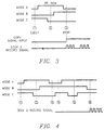
- a mode selection logic signal as shown in Figure 2A generated by the mode switch input according to operation modes of the deck, is applied to the microprocessor 15, which operation modes are shown in the diagram of Figure 2B. For example, if the mode switches A and B are at logic low state, while the mode switch C is at logic high state, then "EJECT” mode is selected. Likewise, if the mode switches A and C are at logic high state, while the mode switch B is at logic low state, then "PLAY”, or "RECORD” mode is operated. Therefore, in order that the operation mode of deck is change from “EJECT” mode to "RECORD” or "PLAYBACK” mode, the input signals from the mode switches A, B and C, as shown in the diagram of Figure 2B, are applied to the microprocessor 15. Thereafter, the microprocessor checks whether to receive a copy key input, and when a desired mode selection signal is received from the mode switches in one cassette deck, generates a servo motor control signal to enable operation of the other deck in response to the key input.
- the copy timing control circuit according to the present invention may be used to prevent the waste of video tape and further to enable the correct tape positioning upon tape-to-tape copying mode. Further, this and other advantages of the invention can be achieved by checking mode switch inputs in one cassette deck and, when a desired mode switch input is received, enabling drive of the other cassette deck to record the video signal from the one cassette deck. That is, synchronism between both decks are effectively obtained.
Landscapes
- Engineering & Computer Science (AREA)
- General Engineering & Computer Science (AREA)
- Multimedia (AREA)
- Signal Processing (AREA)
- Computer Hardware Design (AREA)
- Management Or Editing Of Information On Record Carriers (AREA)
Claims (2)
- Kopierzeitabstimmungs-Steuerschaltkreis zur Verwendung in einem Doppeldeck-Vide-Kassettenrekorder, der mindestens ein erstes Video-Kassettendeck und ein zweites Video-Kassettendeck besitzt, die für ein Kopieren von Videodaten dazwischen von Band zu Band geeignet sind, wobei der Schaltkreis aufweist:eine Modussignal-Eingabeeinrichtung zum Empfangen erster Modus-Auswahlsignale von dem ersten Video-Kassettendeck und zweiter Modus-Auswahlsignale von dem zweiten Video-Kassettendeck, die durch Anwenden von Modus-Schaltern in den jeweiligen Video-Kassettendecks produziert sind;eine Kopiersignal-Eingabeeinrichtung zum Empfangen eines Kopiersignals, das durch Anwenden einer Kopiertaste produziert ist,eine Steuereinrichtung (15), die betriebsmäßig mit der Modussignal-Eingabeeinrichtung und der Kopiersignal-Eingabeeinrichtung verbunden ist, und zwar zum Produzieren eines Servo-Steuersignals in Abängigkeit von einem Empfang eines gegebenen Zustands der Modus-Auswahlsignale und des Kopiersignals;und eine Motor-Treibereinrichtung (5 oder 10), die so verbunden ist, um das Servo-Steuersignal zu empfangen, und zwar zum Steuern des Antriebs des anderen Video-Kassettendecks in Abhängigkeit von dem Servo-Steuersignal;gekennzeichnet dadurch, daß die Steuereinrichtung (15) das Servo-Steuersignal produziert, wenn die ersten Modus-Auswahlsignale für einen Aufzeichnungspausen-Modus des ersten Video-Kassettendecks indikativ sind und die zweiten Modus-Auswahlsignale für einen Playback-Modus oder einen Still-Modus des zweiten Video-Kassettendecks indikativ sind, und wobei die Steuereinrichtung zum Produzieren des Servo-Steuersignals dient, um einen Aufzeichnungsmodus des zweiten Video-Kassettendecks in Abhängigkeit eines Empfangs des Kopiersignals zu ermöglichen, wenn die ersten Modus-Auswahlsignale für einen Stop-Modus des ersten Video-Kassettendecks indikativ sind.
- Verfahren zum Steuern eines Doppeldeck-Video-Kassettenrekorders; der mindestens ein erstes Video-Kassettendeck und ein zweites Video-Kassettendeck besitzt, die für ein Kopieren von Videodaten dazwischen von Band zu Band geeignet sind, wobei das Verfahren die Schritte aufweist:Empfangen von Modus-Signaleingaben der ersten Modus-Auswahlsignale von dem ersten Video-Kassettendeck und zweiter Modus-Auswahlsignale von dem zweiten Video-Kassettendeck, die durch Anwenden von Modus-Schaltern in den jeweiligen Video-Kassettendecks produziert sind;Empfangen einer Kopiersignaleingabe eines Kopiersignals, das durch Anwendung einer Kopiertaste produziert ist,Produzieren eines Servo-Steuersignals von einer Steuereinrichtung (15), die betriebsmäßig mit der Modussignal-Eingabeeinrichtung und einer Kopiersignal-Eingabeeinrichtug verbunden ist, wobei das Servo-Steuersignal von einem Empfang eines gegebenen Zustands der Modus-Auswahlsignale und des Kopiersignals abhängig ist; undSteuern des Antriebs des anderen Video-Kassettendecks durch eine Motor-Treibereinrichtung (5 oder 10), die so verbunden ist, um das Servo-Steuersignal zu empfangen, und zwar in Abhängigkeit des Servo-Steuersignals;gekennzeichnet dadurch, daß die Steuereinrichtung das Servo-Steuersignal produziert, wenn die ersten Modus-Auswahlsignale für einen Aufzeichnungspausen-Modus des ersten Video-Kassettendecks indikatv sind und die zweiten Modus-Auswahlsignale für einen Playback-Modus oder einen Still-Modus des zweiten Video-Kassettendecks indikativ sind, und wobei das Verfahren die Schritte eines Produzierens des Servo-Steuersignals umfaßt, um einen Aufzeichnungs-Modus des zweiten Video-Kassettendecks in Anhängigkeit eines Emfpangs des Kopiersignals zu ermöglichen, wenn die ersten Modus-Auswahlsignale für einen Stop-Modus des ersten Video-Kassettendecks indikativ sind.
Applications Claiming Priority (2)
| Application Number | Priority Date | Filing Date | Title |
|---|---|---|---|
| KR1019900010063A KR950000927B1 (ko) | 1989-07-08 | 1990-07-04 | 급탕기의 온도제어장치 |
| KR1006390 | 1990-07-07 |
Publications (3)
| Publication Number | Publication Date |
|---|---|
| EP0466385A2 EP0466385A2 (de) | 1992-01-15 |
| EP0466385A3 EP0466385A3 (en) | 1993-06-09 |
| EP0466385B1 true EP0466385B1 (de) | 1997-02-19 |
Family
ID=19300862
Family Applications (1)
| Application Number | Title | Priority Date | Filing Date |
|---|---|---|---|
| EP91306009A Expired - Lifetime EP0466385B1 (de) | 1990-07-04 | 1991-07-02 | Kopierzeitsteuervorrichtung für Doppeldeck-Video-Kassettenaufzeichnungsgerät |
Country Status (3)
| Country | Link |
|---|---|
| US (1) | US5282093A (de) |
| EP (1) | EP0466385B1 (de) |
| CA (1) | CA2046405C (de) |
Families Citing this family (2)
| Publication number | Priority date | Publication date | Assignee | Title |
|---|---|---|---|---|
| KR950012190B1 (ko) * | 1991-01-31 | 1995-10-14 | 삼성전자 주식회사 | 더블데크 서보계 제어방법 |
| JP3134894B2 (ja) * | 1992-01-16 | 2001-02-13 | ソニー株式会社 | 複製防止処理の有無検出装置 |
Family Cites Families (9)
| Publication number | Priority date | Publication date | Assignee | Title |
|---|---|---|---|---|
| US5025324A (en) * | 1984-09-07 | 1991-06-18 | Hashimoto Corporation | Method of and apparatus for recording information on both a main recording medium and an endless recording medium for repeated event monitoring |
| US4768110A (en) * | 1984-09-20 | 1988-08-30 | Go-Video, Inc. | Video cassette recorder having dual decks for selective simultaneous functions |
| DE3685383D1 (de) * | 1985-08-30 | 1992-06-25 | Sony Corp | Magnetisches aufzeichnungs- und wiedergabegeraet. |
| JPS6267730A (ja) * | 1985-09-20 | 1987-03-27 | Toshiba Corp | 同期駆動装置 |
| US4763209A (en) * | 1985-09-25 | 1988-08-09 | Sam Sung Electronics Co., Ltd. | Autoreverse double deck system |
| DE3636295C2 (de) * | 1985-10-25 | 1996-02-08 | Samsung Electronics Co Ltd | Anordnung zum Steuern eines Doppeldeck-Bandsystems |
| US5194963A (en) * | 1988-08-09 | 1993-03-16 | Go-Video, Inc. | Dual deck videocassette recorder system |
| JPH0664775B2 (ja) * | 1988-09-22 | 1994-08-22 | ティアツク株式会社 | 再生装置 |
| JPH02260257A (ja) * | 1989-03-31 | 1990-10-23 | Shintomu Kk | ダビング用リモートコントロール機及び簡易型同期ダビング機能付きビデオ装置 |
-
1991
- 1991-06-28 US US07/723,256 patent/US5282093A/en not_active Expired - Lifetime
- 1991-07-02 EP EP91306009A patent/EP0466385B1/de not_active Expired - Lifetime
- 1991-07-05 CA CA002046405A patent/CA2046405C/en not_active Expired - Fee Related
Also Published As
| Publication number | Publication date |
|---|---|
| EP0466385A2 (de) | 1992-01-15 |
| EP0466385A3 (en) | 1993-06-09 |
| CA2046405C (en) | 1999-03-30 |
| US5282093A (en) | 1994-01-25 |
| CA2046405A1 (en) | 1992-01-08 |
Similar Documents
| Publication | Publication Date | Title |
|---|---|---|
| US5442454A (en) | Recording device for electronic still camera | |
| US4488185A (en) | Assemble editing system for video tape recorder | |
| GB2170347A (en) | Automatic program selector of a video tape recorder | |
| US5055937A (en) | Remote controller for two VTR's | |
| EP0228878B1 (de) | Steuereinrichtung und Verfahren zur Datenkopierung (Schneiden) bei Aufnahme- und/oder Wiedergabegeräten | |
| US5282093A (en) | Copy timing control circuit for double-deck video cassette recorder | |
| GB2149192A (en) | Magnetic recording and reproducing apparatus | |
| US4901302A (en) | Apparatus for reproducing information recorded on a compact disc onto a recording medium having two running directions | |
| US6452738B1 (en) | Magnetic recording apparatus and reproducing apparatus | |
| US5623572A (en) | Double-deck videocassette recorder | |
| EP0249466B2 (de) | Betriebsartänderung eines elektronischen Gerätes | |
| JP2583813Y2 (ja) | ダブルデッキvcr用のコピータイミング制御回路 | |
| KR0134488B1 (ko) | 브이씨알의 편집녹화 제어시스템과 그 녹화방법 | |
| JPH0614418B2 (ja) | テ−プレコ−ダの操作装置 | |
| JP2860122B2 (ja) | テープ走行装置 | |
| JP3703151B2 (ja) | 編集システム、再生装置及び再生装置の制御方法 | |
| KR940004591B1 (ko) | 영상기기의 자동편집방법 | |
| JPS61110357A (ja) | 記録再生装置 | |
| JPH10188540A (ja) | 映像信号記録再生装置 | |
| JP2615501B2 (ja) | 磁気記録再生装置 | |
| JP3252601B2 (ja) | ディジタル磁気再生装置 | |
| JPH0619187U (ja) | ビデオカセットレコーダーの編集装置 | |
| JPH03132950A (ja) | ビデオテープの記録並びに再生方法 | |
| JP2728188B2 (ja) | マルチデッキの制御方法及び装置 | |
| KR19990001160U (ko) | 복사용 브이씨알 |
Legal Events
| Date | Code | Title | Description |
|---|---|---|---|
| PUAI | Public reference made under article 153(3) epc to a published international application that has entered the european phase |
Free format text: ORIGINAL CODE: 0009012 |
|
| AK | Designated contracting states |
Kind code of ref document: A2 Designated state(s): DE FR GB NL |
|
| PUAL | Search report despatched |
Free format text: ORIGINAL CODE: 0009013 |
|
| AK | Designated contracting states |
Kind code of ref document: A3 Designated state(s): DE FR GB NL |
|
| 17P | Request for examination filed |
Effective date: 19931117 |
|
| 17Q | First examination report despatched |
Effective date: 19941028 |
|
| GRAG | Despatch of communication of intention to grant |
Free format text: ORIGINAL CODE: EPIDOS AGRA |
|
| GRAH | Despatch of communication of intention to grant a patent |
Free format text: ORIGINAL CODE: EPIDOS IGRA |
|
| GRAH | Despatch of communication of intention to grant a patent |
Free format text: ORIGINAL CODE: EPIDOS IGRA |
|
| GRAA | (expected) grant |
Free format text: ORIGINAL CODE: 0009210 |
|
| AK | Designated contracting states |
Kind code of ref document: B1 Designated state(s): DE FR GB NL |
|
| ET | Fr: translation filed | ||
| REF | Corresponds to: |
Ref document number: 69124716 Country of ref document: DE Date of ref document: 19970327 |
|
| PLBE | No opposition filed within time limit |
Free format text: ORIGINAL CODE: 0009261 |
|
| STAA | Information on the status of an ep patent application or granted ep patent |
Free format text: STATUS: NO OPPOSITION FILED WITHIN TIME LIMIT |
|
| 26N | No opposition filed | ||
| REG | Reference to a national code |
Ref country code: GB Ref legal event code: IF02 |
|
| PGFP | Annual fee paid to national office [announced via postgrant information from national office to epo] |
Ref country code: DE Payment date: 20080711 Year of fee payment: 18 |
|
| PGFP | Annual fee paid to national office [announced via postgrant information from national office to epo] |
Ref country code: FR Payment date: 20080521 Year of fee payment: 18 Ref country code: NL Payment date: 20080703 Year of fee payment: 18 |
|
| PGFP | Annual fee paid to national office [announced via postgrant information from national office to epo] |
Ref country code: GB Payment date: 20080702 Year of fee payment: 18 |
|
| GBPC | Gb: european patent ceased through non-payment of renewal fee |
Effective date: 20090702 |
|
| NLV4 | Nl: lapsed or anulled due to non-payment of the annual fee |
Effective date: 20100201 |
|
| REG | Reference to a national code |
Ref country code: FR Ref legal event code: ST Effective date: 20100331 |
|
| PG25 | Lapsed in a contracting state [announced via postgrant information from national office to epo] |
Ref country code: FR Free format text: LAPSE BECAUSE OF NON-PAYMENT OF DUE FEES Effective date: 20090731 |
|
| PG25 | Lapsed in a contracting state [announced via postgrant information from national office to epo] |
Ref country code: GB Free format text: LAPSE BECAUSE OF NON-PAYMENT OF DUE FEES Effective date: 20090702 |
|
| PG25 | Lapsed in a contracting state [announced via postgrant information from national office to epo] |
Ref country code: DE Free format text: LAPSE BECAUSE OF NON-PAYMENT OF DUE FEES Effective date: 20100202 |
|
| PG25 | Lapsed in a contracting state [announced via postgrant information from national office to epo] |
Ref country code: NL Free format text: LAPSE BECAUSE OF NON-PAYMENT OF DUE FEES Effective date: 20100201 |