EP0466628B1 - Aufhängungsverfahren bei dem eine grössere Steifigkeit in Zustand "Zug" als in Zustand "Druck" benutzt wird, wobei ein Mittel verwendet wird, um den Übergang von einer Steifigkeit zu einer anderen zu dämpfen, und Mittel zur Durchführung des Verfahrens - Google Patents
Aufhängungsverfahren bei dem eine grössere Steifigkeit in Zustand "Zug" als in Zustand "Druck" benutzt wird, wobei ein Mittel verwendet wird, um den Übergang von einer Steifigkeit zu einer anderen zu dämpfen, und Mittel zur Durchführung des Verfahrens Download PDFInfo
- Publication number
- EP0466628B1 EP0466628B1 EP91480101A EP91480101A EP0466628B1 EP 0466628 B1 EP0466628 B1 EP 0466628B1 EP 91480101 A EP91480101 A EP 91480101A EP 91480101 A EP91480101 A EP 91480101A EP 0466628 B1 EP0466628 B1 EP 0466628B1
- Authority
- EP
- European Patent Office
- Prior art keywords
- suspension
- rod
- spring
- plunger
- cylinder
- Prior art date
- Legal status (The legal status is an assumption and is not a legal conclusion. Google has not performed a legal analysis and makes no representation as to the accuracy of the status listed.)
- Expired - Lifetime
Links
Images






Classifications
-
- B—PERFORMING OPERATIONS; TRANSPORTING
- B60—VEHICLES IN GENERAL
- B60G—VEHICLE SUSPENSION ARRANGEMENTS
- B60G17/00—Resilient suspensions having means for adjusting the spring or vibration-damper characteristics, for regulating the distance between a supporting surface and a sprung part of vehicle or for locking suspension during use to meet varying vehicular or surface conditions, e.g. due to speed or load
- B60G17/02—Spring characteristics, e.g. mechanical springs and mechanical adjusting means
- B60G17/021—Spring characteristics, e.g. mechanical springs and mechanical adjusting means the mechanical spring being a coil spring
-
- B—PERFORMING OPERATIONS; TRANSPORTING
- B60—VEHICLES IN GENERAL
- B60G—VEHICLE SUSPENSION ARRANGEMENTS
- B60G11/00—Resilient suspensions characterised by arrangement, location or kind of springs
- B60G11/32—Resilient suspensions characterised by arrangement, location or kind of springs having springs of different kinds
-
- B—PERFORMING OPERATIONS; TRANSPORTING
- B60—VEHICLES IN GENERAL
- B60G—VEHICLE SUSPENSION ARRANGEMENTS
- B60G17/00—Resilient suspensions having means for adjusting the spring or vibration-damper characteristics, for regulating the distance between a supporting surface and a sprung part of vehicle or for locking suspension during use to meet varying vehicular or surface conditions, e.g. due to speed or load
- B60G17/02—Spring characteristics, e.g. mechanical springs and mechanical adjusting means
- B60G17/04—Spring characteristics, e.g. mechanical springs and mechanical adjusting means fluid spring characteristics
-
- F—MECHANICAL ENGINEERING; LIGHTING; HEATING; WEAPONS; BLASTING
- F16—ENGINEERING ELEMENTS AND UNITS; GENERAL MEASURES FOR PRODUCING AND MAINTAINING EFFECTIVE FUNCTIONING OF MACHINES OR INSTALLATIONS; THERMAL INSULATION IN GENERAL
- F16F—SPRINGS; SHOCK-ABSORBERS; MEANS FOR DAMPING VIBRATION
- F16F13/00—Units comprising springs of the non-fluid type as well as vibration-dampers, shock-absorbers, or fluid springs
-
- F—MECHANICAL ENGINEERING; LIGHTING; HEATING; WEAPONS; BLASTING
- F16—ENGINEERING ELEMENTS AND UNITS; GENERAL MEASURES FOR PRODUCING AND MAINTAINING EFFECTIVE FUNCTIONING OF MACHINES OR INSTALLATIONS; THERMAL INSULATION IN GENERAL
- F16F—SPRINGS; SHOCK-ABSORBERS; MEANS FOR DAMPING VIBRATION
- F16F3/00—Spring units consisting of several springs, e.g. for obtaining a desired spring characteristic
- F16F3/08—Spring units consisting of several springs, e.g. for obtaining a desired spring characteristic with springs made of a material having high internal friction, e.g. rubber
- F16F3/10—Spring units consisting of several springs, e.g. for obtaining a desired spring characteristic with springs made of a material having high internal friction, e.g. rubber combined with springs made of steel or other material having low internal friction
-
- F—MECHANICAL ENGINEERING; LIGHTING; HEATING; WEAPONS; BLASTING
- F16—ENGINEERING ELEMENTS AND UNITS; GENERAL MEASURES FOR PRODUCING AND MAINTAINING EFFECTIVE FUNCTIONING OF MACHINES OR INSTALLATIONS; THERMAL INSULATION IN GENERAL
- F16F—SPRINGS; SHOCK-ABSORBERS; MEANS FOR DAMPING VIBRATION
- F16F9/00—Springs, vibration-dampers, shock-absorbers, or similarly-constructed movement-dampers using a fluid or the equivalent as damping medium
- F16F9/32—Details
- F16F9/50—Special means providing automatic damping adjustment, i.e. self-adjustment of damping by particular sliding movements of a valve element, other than flexions or displacement of valve discs; Special means providing self-adjustment of spring characteristics
- F16F9/512—Means responsive to load action, i.e. static load on the damper or dynamic fluid pressure changes in the damper, e.g. due to changes in velocity
Definitions
- the subject of the invention is a suspension of the type using a greater stiffness in the "rebound” stroke than in the "shock" stroke comprising means for smoothing the passage from one stiffness to another.
- means are provided for varying the reference position in "load running order" as a function of the number of people and the amount of freight in the vehicle and when said vehicle does not include a correction device for 'plate.
- the invention differs from this known suspension by a means of softening the change in stiffness.
- the means for smoothing the passage from one stiffness to another consists in the use of an additional elastic element, acting as a progressive stop, mounted in series with the additional spring of the suspension according to the invention, the stiffness of said additional elastic element increases rapidly towards an asymptotic value.
- the additional elastic element mounted in series with the auxiliary spring is a rubber revolution support which is provided with an internal stop which delimits the exact stroke of intervention of said elastic ring.
- the stiffness of the elastic ring can vary by making one or more horizontal holes in the middle part.
- Auxiliary mechanical springs of the helical type may have different characteristics, one part may have linear flexibility, the other part may have, due to its structure, variable flexibility.
- the springs can be used as a means to soften the transition from one stiffness to another stiffness.
- the additional stops for progressive support on the auxiliary spring are provided with a stiffness curve having their own asymptote.
- the means for softening the passage from one stiffness to another consists in the use of an auxiliary spring with variable flexibility.
- auxiliary springs are often springs of the pneumatic or oleo-pneumatic type.
- the elastic element of the auxiliary spring receives an initial pressurization pressure in particular.
- the main thing is to correctly position the breaking point between the two slopes or two stiffnesses, whether this breaking point is softened or not in a curve.
- the adjustment means is a jack hydraulic placed in "interface" between the movable part of the suspension (classic) and the auxiliary spring according to the invention.
- the rod of the movable piston is integral with the suspension while the body of the jack is supported on the auxiliary spring, the jack is provided with two upper and lower chambers with the piston which communicate with each other by a pipe whose passage of oil is controlled by a solenoid valve, the actuator comprises, in its upper part, a reserve of compressed gas maintaining the oil used under pressure by means of a floating separator floor disposed between this reserve and the upper chamber; the lower chamber contains a support spring, the piston head is mounted free on the rod which has only one end stop of the rod which acts as a progressive support stop.
- the solenoid valve opens the passage of oil between the two chambers to allow adjustment after the load so that the piston is pressed against the stop of the rod, the solenoid valve is closed during the journey.
- the auxiliary spring mounted in opposition to the main lifting spring, is mounted coaxially with the hydraulic cylinder which is placed in "interface" between the movable part of the conventional suspension or of the suspension spring and the spring auxiliary.
- the method combines a shock absorber with an auxiliary CONTRACTIVE spring with means for automatic correction of the point of attack.
- the cylinder body is integral with a sheath carrying a stop on which the auxiliary spring comes to bear.
- This auxiliary spring is secured, by its other end, by a support stop, to the body of the shock absorber.
- the piston of the jack is integral with the rod of the shock absorber.
- An internal support spring tends to raise the cylinder body, therefore the assembly of the cylinder body and sleeve, relative to the piston, therefore relative to the damper rod.
- a small pressurization element (accumulator) ensures, continuously, the perfect filling of the cylinder.
- the cylinder is divided into two chambers separated by the piston which is fixed on the shock absorber rod, the two chambers communicate by a pipe which is controlled by a pressurization solenoid valve, the upper chamber is provided with a setting spring support, a pressurization element is connected to the pipe which connects the two chambers, so that the entire cylinder and sheath crew of the auxiliary spring moves by the support spring as soon as the solenoid valve is opened for adjustment according to the load.
- the pressurization gas is enclosed in the jack between the piston and a floating floor partition crossed by the rod of the damper;
- the solenoid valve is integrated in the cylinder body in the form of a valve held in abutment on its seat by an O-ring acting as a spring. Said valve leaves its seat when the solenoid, which is located below, is energized.
- the oil can then move between the top and the bottom of the cylinder by borrowing the annular space peripheral to the cylinder.
- Figure 1 is a schematic view of a means for softening the passage from one stiffness to another, said means is an elastic ring mounted in series with the additional spring of the suspension according to the invention.
- Figures 2 to 6 show the stiffness curves.
- FIG. 2 represents the stiffness curve of the basic assembly with two springs.
- FIG. 3 represents the stiffness curve of the type of progressive stop to be used.
- FIG. 4 represents the curve of the basic assembly enriched with a progression stop.
- FIG. 5 represents the stiffness curve of the assembly using a spring with variable flexibility.
- FIG. 6 represents the curve of mounting stiffness using a spring of the pneumatic or oleopneumatic type.
- a compromise can be obtained by establishing an initial pressure (in particular of pressurization) in the elastic element. There is then a break in the curve, however, much less abrupt than in the case of two mechanical springs of the basic solution.
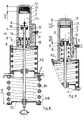
- FIG. 7 is a schematic view of an embodiment of automatic correction of the point of attack of the auxiliary spring, so as to readjust the prestress as a function of the load, in other words, to adjust the breaking point of stiffness during each load variation of the vehicle.
- the adjustment means is a hydraulic cylinder placed in "interface" between the movable part of the elastic suspension and the auxiliary spring.
- the piston rod is integral with the suspension while the cylinder body is supported on the auxiliary spring.
- the piston is mounted freely on the rod which has only one end stop of the rod which acts as a progressive abutment abutment.
- Figure 8 is a view of the embodiment shown in Figure 7 where the solenoid valve is closed and the vehicle is loaded according to the arrows, the rod sinks, the auxiliary spring is released.
- Figure 9 is a view of a detail of Figures 7 and 8 where, after charging the vehicle, the solenoid valve is open, the piston rises to come into contact with the stop of the rod under the effect of the thrust of the support spring. After this adjustment, the solenoid valve is closed.
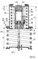
- Figure 10 shows another embodiment where the auxiliary spring is mounted coaxially around the hydraulic cylinder.
- Figure 11 shows the embodiment shown in Figure 10, but where the vehicle is loaded, the rod sinks into the cylinder, the solenoid valve is closed.
- FIG. 12 represents the embodiment represented in FIGS. 10 and 11 where the solenoid valve is open to authorize the repositioning of the piston in the jack and this, without the effort of the bearing spring.
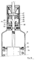
- FIG. 13 shows an embodiment where the hydraulic cylinder is placed between the head of the piston fixed on the end of the shock absorber rod while the body of the cylinder is extended by a chamber of the auxiliary spring which comes, coaxially, surround the body of the shock absorber on which it is slidably mounted.
- Figure 14 is a view of the embodiment shown in Figure 13 where the solenoid valve is closed and where the vehicle is loaded, (see arrows which indicate the air gap that exists, thereby releasing the auxiliary spring).
- Figure 15 is a detail view of the embodiment shown in Figures 13 and 14 but where the solenoid valve is open so as to allow adjustment or adjustment.
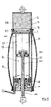
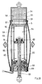
- FIG. 16 is a view showing an embodiment of a auxiliary shock absorber-spring combination according to the invention.
- the piston is fixed on the rod, the pressurization gas is trapped in the cylinder between the piston and a floating floor partition crossed by the damper rod, the solenoid valve is integrated in the body of the cylinder and actuated by a solenoid.
- Figures 17, 18 and 19 show an oleopneumatic auxiliary spring with automatic correction of the point of attack triggered by electromagnetic control. This embodiment is mounted in addition and in parallel with the original elements of the vehicle suspension.
- Figures 20, 21 and 22 relate to an embodiment grouping the damping and auxiliary spring functions. This embodiment is not provided with correction of the point of attack of the auxiliary spring. It uses a telescopic oleopneumatic shock absorber. It is pressurized by an oleopneumatic accumulator which also acts as an auxiliary spring.
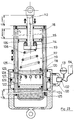
- FIG. 23 schematically represents another mode of auxiliary spring additional to a conventional suspension using two oleopneumatic cylinders.
- One cylinder acts as an auxiliary spring and the other cylinder acts as a means of adjusting the damping as a function of the load.
- the suspension "CONTRACTIVE” (registered trademark), subject of the two patent applications mentioned above, has, as main characteristic, to provide the vehicle on which it is installed, with a suspension whose stiffness is greater in the race lying between the position in "load running order” and the position “wheels hanging” only in the race lying between the position in "load running order” and the position “suspensions crushed until impact stops”.
- the CONTRACTIVE suspension is characterized by the existence of greater stiffness in the "rebound” race than in the "shock” race. When these are represented graphically, it can be observed that this change in stiffness results in a slope break.
- the simple solution consists in mounting in series with the auxiliary spring R2, an additional elastic element 1 acting as an additional progressive stop whose stiffness will increase rapidly to an asymptotic value.
- FIG. 1 represents an experimental solution used on the prototypes and calling upon an additional elastic element 1.
- this assembly is provided with an internal stop 2 at the additional elastic element, which defines the exact course of intervention of the latter.
- the additional elastic element is a rubber revolution support.
- the additional stops for progressive support on the auxiliary spring are provided with a stiffness curve having their own asymptote.
- FIG. 7 is a view of an embodiment of automatic correction of the attack point of the auxiliary spring R2, so as to readjust the prestress as a function of the load, in other words to adjust the stiffness breaking point during each of the vehicle load variations.
- the two springs R1, R2 are supported on the chassis at 4.
- the adjustment means is a hydraulic cylinder 3, placed in "interface” between the movable part 17 of the spring R1 of the suspension 106 and the auxiliary spring R2.
- the head 6 of the movable piston 9 is integral with the suspension 106 while the body of the jack 3 is supported on the auxiliary spring R2.
- the two upper 7 and lower 8 chambers of the movable piston 9 communicate with each other by a pipe 10, the passage of which is controlled by a solenoid valve 11.
- the jack 3 is provided, in its upper part, with a gas reserve 12, compressed gas such as nitrogen, which keeps the oil used under pressure, by means of a floating separator floor 13.
- the rod 14 In its upward movements, the rod 14 can therefore penetrate the jack 3, which only has the effect of pushing the separator floor 13 by the value corresponding to the volume of oil displaced by the penetration of the rod 14.
- the solenoid valve 11 is therefore intended to remain closed when the vehicle is in use. On the other hand, before rolling, at the end of the loading (or unloading of the vehicle), the solenoid valve 11 is open while the movable piston 9 comes to bear on the stop 15 of the rod 14.
- this system makes it possible to automatically reposition the intervention point of the auxiliary spring R2 whatever the load (and therefore the attitude) of the vehicle.
- FIGS 10, 11 and 12 show an embodiment where the auxiliary spring R2 is mounted coaxially with the jack 18.
- said jack 18 which is mounted as an "interface" between the movable part 107 of the suspension or of the suspension spring R1 and the auxiliary spring R2.
- the two springs are supported on the chassis at 19.
- the cylinder 18 has two chambers, an upper chamber 20 and a lower chamber 21. These two chambers communicate with each other by a pipe 22 controlled by a solenoid valve 23.
- a reserve of compressed gas 24 is disposed in the upper part of the separate cylinder 18 of the upper chamber 20 by a movable floor 25.
- a support spring 26 is disposed in the lower chamber 21 between the movable piston 27, in contact with the end stop 28 of the rod 29, and the fixed floor 135 cylinder 18.
- Figures 13, 14 and 15 show another embodiment where the method combines a shock absorber with an auxiliary spring, according to the invention, with a means of automatic correction of the point of attack.
- This embodiment uses a hydraulic cylinder 30, with a damper assembly 34 auxiliary spring R2.
- This embodiment can be used on vehicles where the shock absorber is mounted very distinctly from the main elastic element, for example on a rear axle with drawn wheels and torsion bars.
- the body of the jack 30 is integral with a sheath 31 carrying the stop 32 on which the auxiliary spring R2 comes to bear.
- This auxiliary spring R2 is secured, by its other end, by a support stop 33, to the body of the shock absorber 34.
- the piston 35 of the jack is secured to the rod 36 of the shock absorber 34.
- An internal setting spring in support, spring 37 tends to raise the cylinder body 30, therefore the assembly of the cylinder body and sleeve 31, relative to the piston 35, therefore relative to the rod 36 of the shock absorber 34.
- a small pressurization element (accumulator) 38 ensures, continuously, the perfect filling of the jack 30.
- the upper chamber 39 and the lower chamber 40 on either side of the FIXED piston 35, on the rod 36, communicates by a pipe 104 controlled by a solenoid valve 41.
- the shock absorber 34 is fixed at 42 to the chassis and at 43 on the suspension arm. The operation of this device resembles in all points the device described above.
- FIG. 14 it is highlighted the fact that the whole of the body of the jack 30 and its sleeve 31 sinks, according to arrow F5, around the body of the shock absorber 34 thus releasing the spring R2 of its support stop 33, stop fixed to the body of the shock absorber 34.
- Figure 16 shows another embodiment; a shock absorber and an auxiliary spring according to the invention were used in combination.
- the pressurization gas 45 is enclosed in the body of the jack 46 between the piston 47 and a floating floor partition 48, crossed by the rod 49 of the damper 34.
- the solenoid valve 50 is integrated into the body of the jack 46 in the form of a valve 50 held in abutment on its seat by an O-ring 51 which acts as a seal and as a retaining spring for said valve 50.
- This valve 50 leaves its sits when the solenoid 52, which is located below, is energized; the oil can then move as indicated by arrows F7 in FIG. 16, between the top and the bottom of the jack 46, passing through the peripheral annular space 53 of the jack 46.
- the solenoid 52 is not under tension, the valve 50 remains closed and the jack 46 is locked; for the rest of the operation, this embodiment operates as previously described.
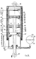
- FIGS. 17, 18 and 19 relate to an auxiliary suspension spring according to the invention produced in oleopneumatic technology and provided with means for automatic correction of the point of attack.
- This embodiment can only be used if it is possible to mount it in addition and in parallel with the original elements of the suspension of a vehicle.
- telescopic shock absorbers Realized in the concept of telescopic shock absorbers, it has a volume of compressed gas 54 in its upper part 55 between the body of the device and a movable floor 56 separating the oil 57 and the gas 58.
- This movable floor 56 at rest, is supported on the top 5 of the inner tube 59, itself closed by a fixed partition 60.
- a free piston 61 identical to those described above.
- the rod 62 of the apparatus also bears on the piston 61 by means of a progressive stop 63.
- the top of the piston 61 is in atmospheric pressure zone 64 (maintained by the hollow rod 62 which comprises a conduit 65 for depressurizing the center of the device), while the underside of the piston 61 is supported on oil 66 in slight pressure by the elasticity of an elastomer sheath 67, when a solenoid valve 68 placed in the foot 69 of the device opens the communication between the interior of the device and the volume contained between the elastic sheath 67 and the outside of said device.
- the oil 66 contained under the piston 61 can travel between the two tubes 59, 133 to the chamber which is located between the upper movable floor 56 and the fixed floor 60 which closes the top of the internal tube 59. In this way, when the piston 61 descends, by the transfer of this oil, the gas 58 in the upper part is compressed by the rise of the movable floor 56 which separates it from the oil 57 or 66.
- the solenoid valve 68 when the vehicle is stationary and at the end of a load variation, the solenoid valve 68 is opened in order to allow the oil to travel between the elastomer sheath 67 and inside the device (see arrows F8), the floating piston 61 therefore takes place in abutment on the progressive stop 63.
- the solenoid valve 68 is closed, the internal oil volume remains invariable and defines the position of the piston 61.
- the rod 62 penetrates into the device, as shown in FIG. 18. Said rod 62 penetrates the device by expelling a little of the air which is located above the piston 61 without generating no oil transfer.
- the piston 61 is biased by means of the progressive stop 63 and by means of the oil transfer, the gas 58, in the upper part 55, is compressed thus ensuring the function spring with variable flexibility.
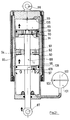
- the embodiment shown in Figures 20, 21 and 22 relates to an embodiment grouping the damping and auxiliary spring functions.
- This handset does not have an attack point correction for the auxiliary spring, its principle of construction gives it a length which limits its field of application.
- its use is entirely possible on the front axles of the MAC PHERSON type (in the inverted position) where the length is not restrictive.
- the load variations on the front are much less than those on the rear axle, which can dispense with the presence of the correction of the point of attack.
- the device operates in circulation continuous oil, it is pressurized by an oleopneumatic accumulator 102 which also acts as an auxiliary spring.
- the shock absorber function is located in the upper part. In this embodiment, there is shown in 80, 81, 82, the shock strokes, in 83 and 84 the rebound strokes, in 85 the zone of opposing stiffness.
- This embodiment is of the telescopic damper type.
- the upper point allows fixing at 86 to the chassis and the lower fixing point 87 allows fixing to the suspension arm by the rod 88.
- a movable piston 89 is fixed on the rod 88, movable piston 89 which has nozzle orifices 90 and valves 91. This set of nozzles and valves acts as shock absorption.
- a fixed floor 92 which is retained by internal shoulders of the cylinder body, shoulders 93. This fixed floor 92 acts as "rebound” damping and also includes a nozzle assembly 94 and valves 95.
- a last piston 96 is mounted in the lower part of the cylinder integral with the rod 88.
- This movable piston 96 can come opposite orifices 97 which allow the oil to circulate towards an oil reserve 99 arranged coaxially to the cylinder body and retained by an elastomer skirt 98; this reserve of oil 99 allows transfer to the accumulator during the phases where the CONTRACTIVE suspension is operating.
- the lower part of the jack 100 is connected to an oleopneumatic accumulator 102, part of which comprises compressed gas 103 and the other part of oil 101.
- the device is in the rebound damping phase.
- the oil is compressed between the piston 89 (whose valves 91 have closed the nozzles 90) and the fixed floor 92 which laminates the oil in its nozzles 94 while opposing the elasticity of its valves 95.
- Figure 21 shows the device in shock absorption phase.
- the oil is compressed between the upper part of the apparatus, the passage of which has been obstructed by the valve 105 and the movable piston 89 which laminates the oil in its nozzles 90 while opposing the elasticity of its valves. 91.
- FIG. 22 represents the apparatus in "CONTRACTIVE phase".
- the piston 96 descending, has passed the line of orifice 97; the valve 109 obstructs the passage 108.
- the oil contained under the piston 96 is then sent to the accumulator 102, which generates "the contractual force" on the rod. the device.
- the embodiment shown in Figure 23 relates to a device of the type shown in Figure 17 but whose correction required by the load variations, is performed by an annular cylinder to the device.
- the rod 112 is hollow to allow the volume 117 to be brought to atmospheric pressure.
- the rod is introduced into the apparatus while the movable piston 115 remains resting on the stop 135.
- the movable piston 115 is driven by the rod 112 and the stop 114.
- the oil is driven from the volume 116 to the volume 122 by passing through the annular space between the tubes 119 and 126, which causes the displacement of the movable floor 124 and the compression of the gas contained in 125. This generates "the contractual force".
- the cylindrical tube 126 behaves like a piston in the body of the jack 127. It determines two chambers 128, 129. These two chambers 128, 129 communicate with each other by a pipe 130 provided with an oleopneumatic reservoir 131 and controlled by a solenoid valve 132.
- This set allows the device to be adjusted according to the vehicle load.
- This embodiment can be provided with an accelerometer 134 which controls the valve or solenoid valve 132 and blocks said valve on each horizontal acceleration of the vehicle.
Landscapes
- Engineering & Computer Science (AREA)
- Mechanical Engineering (AREA)
- General Engineering & Computer Science (AREA)
- Physics & Mathematics (AREA)
- Fluid Mechanics (AREA)
- Vehicle Body Suspensions (AREA)
- Springs (AREA)
- Fluid-Damping Devices (AREA)
Claims (15)
- Aufhängung für ein Fahrzeugrad, mit wenigstens einem Hauptunterstützungselement (R1) und einem elastischen Hilfselement (R2), die einander entgegengesetzt oder nicht entgegengesetzt montiert sind, wobei die Aufhängung (2) unterschiedliche Steifigkeiten beim Vollausschlag des Fahrzeugrads auf der einen beziehungsweise der anderen Seite der Betriebsbereitschaftsposition der Aufhängung verwendet, wobei der Umkehrpunkt zwischen den zwei Steifigkeiten in der Nähe der Betriebsbereitschaftsposition der Aufhängung liegt, und die Steifigkeit zwischen der Betriebsbereitschaftsposition und der Position mit hängendem Rad größer ist als die beim Eindrücken des Rades zwischen der Betriebsbereitschaftsposition und der Anschlagposition beobachtete Steifigkeit,
dadurch gekennzeichnet,
daß sie ein Mittel zum Glätten des Übergangs der Steifigkeit (1; 15; 63; 114) verwendet. - Aufhängung nach Anspruch 1,
dadurch gekennzeichnet, daß sie ein Regelmittel verwendet, um den Punkt der Steifigkeitsänderung bei jeder Laständerung des Fahrzeugs anzupassen. - Aufhängung nach Anspruch 1,
dadurch gekennzeichnet, daß das elastische Hilfselement aus einer Reihenanordnung mit einer Hilfsfeder (R2) und einem zusätzlichen elastischen Element (1) besteht, das als fortschreitender zusätzlicher Anschlag dient, dessen Steifigkeit schnell gegen einen asymptotischen Wert wächst; wobei die Anordnung mit einem inneren Anschlag (2) im elastischen Element (1) versehen ist, das den genauen Verlauf von dessen Wirkbewegung begrenzt. - Aufhängung nach Anspruch 1,
dadurch gekennzeichnet, daß das Mittel zur Glättung der Steifigkeitsänderung in der Verwendung einer Hilfsfeder mit veränderlicher Flexibilität besteht. - Aufhängung nach Anspruch 1,
dadurch gekennzeichnet,- daß als elastische Elemente zwei Federn, darunter eine Hauptunterstützungsfeder (R1) und eine entgegengesetzt montierte Hilfsfeder (R2), verwendet werden,- daß das Regelmittel zum Einstellen des Steifigkeitsänderungspunkts bei jeder Beladungsänderung des Fahrzeugs ein Hydraulikzylinder (3) ist, der als Übergang zwischem dem beweglichen Bereich (17) der Hauptfeder (R1) der Aufhängung (106) und der Hilfsfeder (R2) angeordnet ist. - Aufhängung nach Anspruch 5,
dadurch gekennzeichnet,- daß der Hydraulikzylinder (3) einen beweglichen Kolben (9), eine fest am beweglichen Bereich (17) der Aufhängung (106) montierte Stange (14) und einen Zylinderkörper (3) umfaßt, der die Hilfsfeder (R2) belastet, wobei der Zylinder (3) mit zwei Kammern (7, 8) oberhalb beziehungsweise unterhalb des beweglichen Kolbens (9) versehen ist, die untereinander durch eine Leitung (10) in Verbindung stehen, in der der Öldurchgang durch ein Magnetventil (11) gesteuert wird, wobei der Zylinder (3) in seinem oberen Bereich eine Druckgasreserve (12) aufweist, die das verwendete Öl über eine schwebende Trennwand (13) unter Druck hält, die zwischen dieser Reserve (12) und der oberen Kammer (7) angeordnet ist, wobei die untere Kammer (8) eine Belastungsfeder (16) zur Belastung des beweglichen Kolbens an dem an der Stange (14) montierten Kopf (6) enthält und einen Endanschlag (15) für die Stange (14) aufweist, der als fortschreitender Belastungsanschlag (15) dient. - Aufhängung nach Anspruch 6,
dadurch gekennzeichnet, daß das Magnetventil (11) den Öldurchgang zwischen den zwei Kammern (7, 8) öffnet, um die Einstellung nach der Beladung so zu ermöglichen, daß der Kolben (9) am Anschlag (15) der Stange (14) anliegt, wobei das Magnetventil (11) während der Fahrt geschlossen ist. - Aufhängung nach einem der Ansprüche 5 oder 6,
dadurch gekennzeichnet, daß die Hilfsfeder (R2), die der Hauptunterstützungsfeder (R1) entgegengesetzt montiert ist, koaxial mit dem Hydraulikzylinder (18) montiert ist, der als Übergang zwischen dem beweglichen Bereich (107) der Aufhängungsfeder (R1) und der Hilfsfeder (R2) angeordnet ist. - Aufhängung nach Anspruch 5,
dadurch gekennzeichnet, daß ein Stoßdämpfer (34) mit einer Hilfsfeder (R2) mit einem Mittel zu automatischen Korrektur des Einsetzpunkts kombiniert ist, wobei der Zylinderkörper (30) fest mit einer Hülse (31) verbunden ist, welche einen Anschlag (32) trägt, auf dem die Hilfsfeder (R2) lastet; wobei die Hilfsfeder (R2) über ihr anderes Ende mit einem Anschlag (33) des Körpers des Stoßdämpfers (34) verbunden ist; der Kolben (35) des Zylinders mit der Stange (36) des Stoßdämpfers (34) fest verbunden ist; eine interne Belastungsfeder (37) wirkt, um den Zylinderkörper (30) und die Hülse (31) gegen den Kolben (35) anzuheben; ein kleines Druckelement (38) fortlaufend die vollständige Füllung des Zylinders (30) sicherstellt; der Zylinder (30) in zwei durch den Kolben (35) getrennte Kammern unterteilt ist, wobei die zwei Kammern (39, 40) durch eine Leitung (104) verbunden sind, die durch ein Magnetventil (41) zur Druckbeaufschlagung gesteuert wird, die obere Kammer (39) mit der Belastungsfeder (37) versehen ist, das Druckelement (38) an die Leitung (104) angeschlossen ist, die die zwei Kammern (39, 40) verbindet, so daß beim Öffnen des Magnetventils (41) zur ladungsabhängigen Regelung die Gesamtheit von Zylinder (30) und Hülse (31) durch die Belastungsfeder (37) bewegt wird. - Aufhängung nach Anspruch 5,
dadurch gekennzeichnet, daß in Kombination ein Stoßdämpfer (34) und eine Hilfsfeder (32) verwendet werden, ein Druckgas (45) im Zylinderkörper (46) zwischem dem Kolben (47) und einer schwebenden Trennwand (48) eingeschlossen ist, die von der Stange (49) des Stoßdämpfers (34) durchlaufen wird, ein Magnetventil (50) in den Zylinderkörper (46) in Form einer Ventilklappe (50) integriert ist, die auf ihrem Sitz angedrückt durch eine torusförmige Dichtung (51) gehalten wird, die als Dichtung und als Feder zum Halten der Ventilklappe (50) dient, wobei die Ventilklappe (50) ihren Sitz verläßt, wenn eine darunterliegende Magnetspule (52) unter Spannung gesetzt wird, wobei sich dann das Öl zwischen dem oberen und unteren Bereich des Zylinders (46) durch den den Zylinder (46) umgebenden ringförmigen Zwischenraum (53) bewegen kann und die Ventilklappe (50) gesperrt bleibt und der Zylinder (46) arretiert ist, wenn die Spule (52) nicht unter Spannung steht. - Aufhängung nach Anspruch 2,
dadurch gekennzeichnet, daß sie eine in der Pneumatik-Ölhydraulik-Technik ausgeführte Hilfsaufhängungsfeder verwendet, die mit einem Mittel zur automatischen Korrektur des Einsetzpunkts versehen ist, das zusätzlich und parallel zu den ursprünglichen Aufhängungselementen eines Fahrzeugs montiert ist. - Aufhängung nach Anspruch 11,
dadurch gekennzeichnet, daß sie nach dem Konzept eines Teleskopstoßdämpfers verwirklicht ist, der ein Druckgasvolumen (54) in seinem oberen Bereich (55) zwischen dem Körper des Stoßdämpfers und einer beweglichen Trennwand (56) zur Trennung von Öl (57) und Gas (58) besitzt, welche bewegliche Trennwand (56) in Ruhestellung auf der Oberseite (5) eines inneren Rohrs (59) lastet, das seinerseits durch eine feste Trennwand (60) verschlossen ist, daß das innere Rohr (59) einen Kolben (61) aufweist, der, bezogen auf eine Stange (62), frei beweglich ist, die gleichzeitig als Druckentlastungsleitung der Mitte der Vorrichtung dient; daß die Stange (62) der Vorrichtung über einen fortschreitenden Anschlag ebenfalls auf dem Kolben (61) lastet; daß die Oberseite des Kolbens (61) in einem Abschnitt (64) mit atmosphärischem Druckliegt, der von der hohlen Stange (62) aufrechterhalten wird, die eine Druckentlastungsleitung (65) für die Mitte der Vorrichtung umfaßt, wohingegen die Unterseite des Kolbens (61) auf Öl lastet, das aufgrund der Elastizität einer Hülse (67) aus Elastomer unter leichtem Druck steht, wenn ein im Fuß (69) der Vorrichtung angeordnetes Magnetventil (68) die Verbindung zwischen dem Inneren der Vorrichtung und dem Volumen zwischen der elastischen Hülse (67) und dem Äußeren der Vorrichtung öffnet; daß das unter dem Kolben (61) enthaltene Öl (66) sich zwischen dem inneren Rohr (59) und dem Körper (133) bis in die Kammer bewegen kann, die sich zwischen der beweglichen Trennwand (56) und der festen Trennwand (60) befindet; und daß das Gas im oberen Bereich durch den Anstieg der beweglichen Trennwand (56), die es vom Öl (57, 66) trennt, komprimiert wird, wenn der Kolben (61) sich durch Verlagerung dieses Öls abwärts bewegt. - Aufhängung nach Anspruch 1,
dadurch gekennzeichnet, daß sie vom Teleskopstoßdämpfertyp ist, deren oberer Punkt die Befestigung (86) am Fahrgestell ermöglicht, und deren unterer Befestigungspunkt (87) die Befestigung am Aufhängungsarm über die Stange (88) ermöglicht, wobei die Stange (88) mit einem an der Stange (88) befestigten beweglichen Kolben (89) versehen ist, der Ansatzöffnungen (90) und Ventilklappen (91) aufweist, wobei das System von Ansatzöffnungen und Ventilklappen zur Stoßdämpfung dient; daß eine feste Trennwand (92) in der Mitte des Zylinderkörpers angeordnet und durch innere Schultern (93) des Zylinderkörpers gehalten wird; daß diese feste Trennwand (92) zur Dämpfung beim Zurückprallen dient und ebenfalls ein System von Ansatzöffnungen (94) und Ventilklappen (95) aufweist; daß ein letzter Kolben (96) im unteren Bereich des Zylinders an der Stange (88) montiert ist und vor Öffnungen (97) gelangen kann, die es dem Öl ermöglichen, zu einem koaxial zum Zylinderkörper angeordneten Ölvorrat (99) zu fließen, der von einer Schürze aus Elastomer (98) gehalten wird; wobei dieser Ölvorrat (99) die Verlagerung in den Akkumulator ermöglicht, wenn das Rad zwischen der Fahrbereitschaftsposition und dem Stoßanschlag ausgelenkt ist. - Aufhängung nach Anspruch 11,
dadurch gekennzeichnet, daß zur aufgrund der Beladungsänderungen erforderlichen Korrektur ein ringförmiger Zylinder verwendet wird, daß die Stange (112) hohl ist, damit das Volumen (117) unter Atmosphärendruck gesetzt werden kann, daß die Stange (112) im Laufe der Stoßbewegung in die Vorrichtung eindringt, wohingegen der bewegliche Kolben (115) weiterhin auf dem Anschlag (135) lastet, daß der bewegliche Kolben im Laufe der Entspannungsbewegung von der Stange (112) und dem Anschlag (114) mitgenommen wird; daß das Öl vom Volumen (116) über den ringförmigen Zwischenraum zwischen den Rohren (119) und (126) in das Volumen (122) getrieben wird, was die Verlagerung der beweglichen Wand (124) und die Kompression des in (125) enthaltenen Gases mit sich bringt; das zylindrische Rohr (126) sich wie ein Kolben im Körper des Zylinders (127) verhält, wobei der Kolben zwei Kammern (128, 129) definiert, die untereinander durch eine Leitung (130) verbunden sind, die mit einem ölpneumatischen Reservoir (131) versehen und durch ein Magnetventil (132) gesteuert ist. - Aufhängung nach Anspruch 14,
dadurch gekennzeichnet, daß diese mit einer Geschwindigkeitsmeßeinrichtung (134) versehen ist, die die Ventilklappe oder das Magnetventil (132) steuert und die Ventilklappe bei jeder horizontalen Beschleunigung des Fahrzeugs blockiert.
Applications Claiming Priority (2)
| Application Number | Priority Date | Filing Date | Title |
|---|---|---|---|
| FR9008859 | 1990-07-06 | ||
| FR909008859A FR2664210B1 (fr) | 1990-07-06 | 1990-07-06 | Procede de suspension du type utilisant une raideur plus grande dans la course de "rebond" que dans la course de "choc" comportant un moyen pour adoucir le passage d'une raideur a l'autre et son dispositif de mise en óoeuvre. |
Publications (2)
| Publication Number | Publication Date |
|---|---|
| EP0466628A1 EP0466628A1 (de) | 1992-01-15 |
| EP0466628B1 true EP0466628B1 (de) | 1994-12-28 |
Family
ID=9398623
Family Applications (1)
| Application Number | Title | Priority Date | Filing Date |
|---|---|---|---|
| EP91480101A Expired - Lifetime EP0466628B1 (de) | 1990-07-06 | 1991-07-03 | Aufhängungsverfahren bei dem eine grössere Steifigkeit in Zustand "Zug" als in Zustand "Druck" benutzt wird, wobei ein Mittel verwendet wird, um den Übergang von einer Steifigkeit zu einer anderen zu dämpfen, und Mittel zur Durchführung des Verfahrens |
Country Status (9)
| Country | Link |
|---|---|
| US (1) | US5183285A (de) |
| EP (1) | EP0466628B1 (de) |
| JP (1) | JP3182657B2 (de) |
| AT (1) | ATE116219T1 (de) |
| DE (1) | DE69106250T2 (de) |
| DK (1) | DK0466628T3 (de) |
| ES (1) | ES2068552T3 (de) |
| FR (1) | FR2664210B1 (de) |
| GR (1) | GR3015280T3 (de) |
Cited By (1)
| Publication number | Priority date | Publication date | Assignee | Title |
|---|---|---|---|---|
| US9656529B2 (en) | 2013-02-12 | 2017-05-23 | Piaggio & C. S.P.A. | Suspension group in particular for motorized vehicles |
Families Citing this family (27)
| Publication number | Priority date | Publication date | Assignee | Title |
|---|---|---|---|---|
| FR2677929A1 (fr) * | 1991-06-24 | 1992-12-24 | Bianchi Mauro Sa | Procede de suspension pour vehicules utilisant deux raideurs, destinees respectivement a l'obtention d'un bon niveau de confort et d'un bon niveau de comportement. |
| DE4231641C2 (de) * | 1992-09-22 | 1996-12-12 | Daimler Benz Ag | Federbein für Federungssysteme von Kraftfahrzeugen |
| IE930514A1 (en) * | 1993-07-12 | 1995-01-25 | Kildalkey Ltd | Hydrostatic elastic system having variable flexibility for¹suspensions of road or rail vehicles |
| IT1269678B (it) * | 1994-04-15 | 1997-04-08 | Digitek Srl | Ammortizzatore idraulico a reazione autocorretta |
| US5720473A (en) * | 1996-03-26 | 1998-02-24 | Thomas; James Gregory | Shock absorber |
| FR2757107B1 (fr) * | 1996-12-12 | 1999-03-12 | Bianchi Mauro Sa | Suspensions de roue de vehicule utilisant un ressort combine a une armature souple destinee a modifier sa courbe de raideur |
| FR2805871B1 (fr) * | 2000-03-06 | 2002-06-14 | Delcamp En | Amortisseur |
| US6830256B2 (en) * | 2002-03-16 | 2004-12-14 | Peter E. Bryant | Method and apparatus for rebound control |
| EP1485635A4 (de) * | 2002-03-18 | 2005-09-14 | S Gregory Smith | Buchse mit variabler reaktion |
| FR2840256A1 (fr) * | 2002-05-28 | 2003-12-05 | Bianchi Mauro Sa | Organe de suspension pour vehicule et suspension ainsi equipee |
| WO2005111459A1 (fr) * | 2004-04-26 | 2005-11-24 | Amortisseur Donerre | Systeme amortisseur a detente rapide et butee hydraulique de fin de course et procede d’utilisation |
| DE102006008608B4 (de) * | 2006-02-24 | 2009-07-02 | Zf Friedrichshafen Ag | Radaufhängung |
| FR2977833B1 (fr) | 2011-07-11 | 2014-02-28 | Bianchi Mauro Sa | Procede de suspension et ensemble amortisseur destine a un vehicule automobile |
| CN105156581A (zh) * | 2013-07-29 | 2015-12-16 | 蒋盘君 | 一种基于砖坯码跺作业的机器人的全自动制砖系统 |
| CN105179585A (zh) * | 2013-07-29 | 2015-12-23 | 蒋盘君 | 一种基于机器人的全自动制砖系统 |
| FR3025573A1 (fr) * | 2014-09-05 | 2016-03-11 | Thales Sa | Dispositif d'isolation vibratoire |
| WO2017162951A1 (fr) * | 2016-03-25 | 2017-09-28 | Psa Automobiles S.A. | Systeme de suspension hydraulique d'un vehicule |
| IT201600117315A1 (it) * | 2016-11-21 | 2018-05-21 | Sistemi Sospensioni Spa | Sospensione per ruota di veicolo con sistema di controllo attivo per regolare in modo controllato la rigidezza complessiva della sospensione. |
| CN107757290B (zh) * | 2017-10-31 | 2023-12-26 | 杭州极木科技有限公司 | 一种重载轮式机器人可调悬架装置 |
| US11021029B2 (en) | 2018-02-28 | 2021-06-01 | Eric Harrison | Vehicle suspension assembly and method |
| DE102018206605A1 (de) * | 2018-04-27 | 2019-10-31 | Bayerische Motoren Werke Aktiengesellschaft | Fahrzeug-Radaufhängung mit einer Tragfeder und einem mit dieser in Reihe schaltbaren Zusatz-Federelement |
| CN108425982A (zh) * | 2018-05-11 | 2018-08-21 | 南京世界村汽车动力有限公司 | 一种多级减震发动机拉杆 |
| CN108973578B (zh) * | 2018-07-23 | 2021-09-14 | 浙江大学滨海产业技术研究院 | 基于深度强化学习的agv悬挂系统弹性调节方法 |
| RU2705604C1 (ru) * | 2019-02-12 | 2019-11-11 | Алексей Васильевич Гаврилов | Пружинная подвеска с регулируемым дорожным просветом |
| CN111038204B (zh) * | 2020-01-08 | 2021-09-21 | 浙江科技学院 | 方程式赛车用变刚度液压机构 |
| CN121224360A (zh) * | 2020-08-21 | 2025-12-30 | 多媒体股份有限公司 | 可调节驾乘高度的双刚度车辆悬架系统 |
| CN114987134B (zh) * | 2022-04-24 | 2024-08-30 | 玛瑜科创服务(南京)有限公司 | 一种随路况自调节汽车悬挂 |
Family Cites Families (23)
| Publication number | Priority date | Publication date | Assignee | Title |
|---|---|---|---|---|
| DE630427C (de) * | 1936-05-27 | Rolf Schroedter Dr Ing | Abfederung fuer Kraftfahrzeuge | |
| BE397344A (de) * | ||||
| DE349582C (de) * | 1920-12-12 | 1922-03-06 | Paul Petersdorff | Mit einer Wippschaukel verbundene Schwingschaukel |
| GB349582A (en) * | 1929-11-25 | 1931-05-26 | George Carwardine | Improvements in suspensions for automobiles and the like |
| BE508823A (de) * | 1952-02-04 | |||
| FR1181645A (fr) * | 1957-08-26 | 1959-06-17 | Veb | Amortisseurs pour véhicules |
| US3002743A (en) * | 1958-09-02 | 1961-10-03 | Thompson Ramo Wooldridge Inc | Hydro-pneumatic strut |
| FR1376235A (fr) * | 1962-11-28 | 1964-10-23 | Stabilus | Perfectionnements aux amortisseurs de chocs et analogues |
| US3297312A (en) * | 1965-03-29 | 1967-01-10 | James E Hines | Combination shock absorber and spring |
| FR94481E (fr) * | 1967-05-17 | 1969-08-22 | Regie Nationale Des Usines Ran | Correcteur de flexibilité pour suspension de véhicule. |
| US3720425A (en) * | 1969-08-05 | 1973-03-13 | Aisin Seiki | Process and apparatus for the adjustment of the height of the chassis of a wheeled vehicle |
| BE756950A (fr) * | 1969-10-01 | 1971-03-16 | Tokico Ltd | Mecanisme de suspension pour vehicules |
| FR2125217B1 (de) * | 1971-02-19 | 1975-01-17 | Saviem | |
| DE2351829A1 (de) * | 1973-10-16 | 1975-04-17 | Volkswagenwerk Ag | Hydraulischer pralldaempfer |
| HU174666B (hu) * | 1977-06-30 | 1980-03-28 | Autoipari Kutato Intezet | Amortizator s vozdushnoj pruzhinoj i teleskopicheskim gasitelem kolebanij k avtomashinam dlja amortizacii kolebanij v zavisimosti ot nagruzki |
| HU188137B (en) * | 1980-09-18 | 1986-03-28 | Ganz-Mavag Mozdony- Vagon- Es Gepgyar,Hu | Intermediate spring cup serving for connecting a pair of compression springs |
| US4415146A (en) * | 1981-02-03 | 1983-11-15 | Sitko James R | Suspension strut assembly |
| DE3433918C1 (de) * | 1984-09-15 | 1986-03-13 | Boge Gmbh, 5208 Eitorf | Selbstpumpendes,hoehenverstellbares Federbein fuer Fahrzeuge |
| FR2582592B1 (fr) * | 1985-05-29 | 1989-08-04 | Renault Vehicules Ind | Dispositif de nivellements pour suspension de vehicule et systeme de correction d'assiette comportant un tel dispositif |
| EP0318817A3 (de) * | 1987-11-28 | 1990-05-30 | Hermann Hemscheidt Maschinenfabrik GmbH & Co. | Hydro-pneumatischer Stoss- und Schwingungsdämpfer mit Innenrohr |
| DE3835917A1 (de) * | 1988-10-21 | 1990-04-26 | Bittel Karl Dr Ing | Hydraulischer stossdaempfer |
| DE3840156A1 (de) * | 1988-11-29 | 1990-05-31 | Freudenberg Carl Fa | Elastisches lager fuer einen koerper |
| DE3910119C2 (de) * | 1989-03-29 | 1994-03-24 | Hemscheidt Maschf Hermann | Hydropneumatisches Federungssystem |
-
1990
- 1990-07-06 FR FR909008859A patent/FR2664210B1/fr not_active Expired - Fee Related
-
1991
- 1991-07-03 EP EP91480101A patent/EP0466628B1/de not_active Expired - Lifetime
- 1991-07-03 DK DK91480101.4T patent/DK0466628T3/da active
- 1991-07-03 AT AT91480101T patent/ATE116219T1/de not_active IP Right Cessation
- 1991-07-03 DE DE69106250T patent/DE69106250T2/de not_active Expired - Fee Related
- 1991-07-03 ES ES91480101T patent/ES2068552T3/es not_active Expired - Lifetime
- 1991-07-05 JP JP26149191A patent/JP3182657B2/ja not_active Expired - Fee Related
- 1991-07-08 US US07/726,987 patent/US5183285A/en not_active Expired - Lifetime
-
1995
- 1995-03-03 GR GR950400456T patent/GR3015280T3/el unknown
Non-Patent Citations (1)
| Title |
|---|
| WO 91 04876 * |
Cited By (1)
| Publication number | Priority date | Publication date | Assignee | Title |
|---|---|---|---|---|
| US9656529B2 (en) | 2013-02-12 | 2017-05-23 | Piaggio & C. S.P.A. | Suspension group in particular for motorized vehicles |
Also Published As
| Publication number | Publication date |
|---|---|
| FR2664210B1 (fr) | 1994-10-21 |
| JPH06129471A (ja) | 1994-05-10 |
| DK0466628T3 (da) | 1995-05-15 |
| US5183285A (en) | 1993-02-02 |
| ATE116219T1 (de) | 1995-01-15 |
| ES2068552T3 (es) | 1995-04-16 |
| EP0466628A1 (de) | 1992-01-15 |
| DE69106250T2 (de) | 1995-08-03 |
| FR2664210A1 (fr) | 1992-01-10 |
| DE69106250D1 (de) | 1995-02-09 |
| JP3182657B2 (ja) | 2001-07-03 |
| GR3015280T3 (en) | 1995-06-30 |
Similar Documents
| Publication | Publication Date | Title |
|---|---|---|
| EP0466628A1 (de) | Aufhängungsverfahren bei dem eine grössere Steifigkeit in Zustand "Zug" als in Zustand "Druck" benutzt wird, wobei ein Mittel verwendet wird, um den Übergang von einer Steifigkeit zu einer anderen zu dämpfen, und Mittel zur Durchführung des Verfahrens | |
| FR2677929A1 (fr) | Procede de suspension pour vehicules utilisant deux raideurs, destinees respectivement a l'obtention d'un bon niveau de confort et d'un bon niveau de comportement. | |
| EP0275735A1 (de) | Landungsbein mit Dämpferheber und Flugzeugfahrgestelle, ausgerüstet mit einem derartigen Landungsbein | |
| FR2663100A1 (fr) | Coussin d'air a raidissement reversible, en particulier pour un vehicule. | |
| EP4022196B1 (de) | Hydraulischer anschlag für eine kraftfahrzeugaufhängung mit trägheitsmasse | |
| EP0051506A1 (de) | Dämpferheber | |
| EP3918226B1 (de) | Hydraulischer anschlag für eine kraftfahrzeugaufhängung mit trägheitsmasse | |
| FR2493256A1 (fr) | Fourche avant de motocyclette | |
| EP3717792B1 (de) | Hydraulischer stossdämpfer mit selbsteinstellbarem lastabhängigem endanschlag | |
| WO2020193885A1 (fr) | Amortisseur avec butee de fin de course auto-adaptable equipee d'un boisseau flottant | |
| CH553353A (fr) | Dispositif amortisseur. | |
| FR2777058A1 (fr) | Dispositif de suspension et d'amortissement a deux combines suspension-amortisseur | |
| EP3861229B1 (de) | Hydraulischer stossdämpfer mit hydraulischer endanschlagsbegrenzung an einer selbst einstellbaren höhe | |
| FR2695698A1 (fr) | Dispositif oléopneumatique d'amortissement variable et réglable. | |
| EP0118335B1 (de) | Hydropneumatische Aufhängung mit totaler Dämpfung | |
| WO2021005180A1 (fr) | Butée hydraulique pour amortisseur | |
| FR3068932B1 (fr) | Dispositif de suspension pour siege de vehicule comportant un support hydraulique associe a des verins. | |
| FR2726791A1 (fr) | Perfectionnements a un dispositif d'asservissement passif de la precontrainte des suspensions d'un vehicule | |
| FR3047444A1 (fr) | Systeme de suspension a barre anti devers d'un vehicule | |
| FR3010757A1 (fr) | Amortisseur hydraulique comprenant une chambre de compensation deportee recevant des butees de detente et d'attaque | |
| EP3942195B1 (de) | Fluiddämpfer aufweisend einen selbstanpanssenden anschlag mit öffnungen an der stange | |
| FR2565170A1 (fr) | Suspension hydropneumatique avec correction de niveau pour vehicules | |
| EP3942196A1 (de) | Stossdämpfer mit einem selbstanpassenden endanschlag versehen mit einer kammer vor einem stopfen | |
| FR2647061A1 (fr) | Procede de suspension a double flexibilite en opposition pour vehicule automobile et dispositif pour la mise en oeuvre | |
| FR3093155A1 (fr) | Amortisseur hydraulique equipe d’une butee de fin de course auto-adaptable |
Legal Events
| Date | Code | Title | Description |
|---|---|---|---|
| PUAI | Public reference made under article 153(3) epc to a published international application that has entered the european phase |
Free format text: ORIGINAL CODE: 0009012 |
|
| AK | Designated contracting states |
Kind code of ref document: A1 Designated state(s): AT BE CH DE DK ES FR GB GR IT LI LU NL SE |
|
| 17P | Request for examination filed |
Effective date: 19920626 |
|
| 17Q | First examination report despatched |
Effective date: 19930819 |
|
| GRAA | (expected) grant |
Free format text: ORIGINAL CODE: 0009210 |
|
| AK | Designated contracting states |
Kind code of ref document: B1 Designated state(s): AT BE CH DE DK ES FR GB GR IT LI LU NL SE |
|
| REF | Corresponds to: |
Ref document number: 116219 Country of ref document: AT Date of ref document: 19950115 Kind code of ref document: T |
|
| REF | Corresponds to: |
Ref document number: 69106250 Country of ref document: DE Date of ref document: 19950209 |
|
| ITF | It: translation for a ep patent filed | ||
| GBT | Gb: translation of ep patent filed (gb section 77(6)(a)/1977) |
Effective date: 19950221 |
|
| REG | Reference to a national code |
Ref country code: ES Ref legal event code: FG2A Ref document number: 2068552 Country of ref document: ES Kind code of ref document: T3 |
|
| REG | Reference to a national code |
Ref country code: DK Ref legal event code: T3 |
|
| REG | Reference to a national code |
Ref country code: GR Ref legal event code: FG4A Free format text: 3015280 |
|
| PLBE | No opposition filed within time limit |
Free format text: ORIGINAL CODE: 0009261 |
|
| STAA | Information on the status of an ep patent application or granted ep patent |
Free format text: STATUS: NO OPPOSITION FILED WITHIN TIME LIMIT |
|
| 26N | No opposition filed | ||
| REG | Reference to a national code |
Ref country code: GB Ref legal event code: IF02 |
|
| PGFP | Annual fee paid to national office [announced via postgrant information from national office to epo] |
Ref country code: AT Payment date: 20050620 Year of fee payment: 15 |
|
| PGFP | Annual fee paid to national office [announced via postgrant information from national office to epo] |
Ref country code: GR Payment date: 20050623 Year of fee payment: 15 |
|
| PGFP | Annual fee paid to national office [announced via postgrant information from national office to epo] |
Ref country code: ES Payment date: 20050624 Year of fee payment: 15 |
|
| PGFP | Annual fee paid to national office [announced via postgrant information from national office to epo] |
Ref country code: GB Payment date: 20050627 Year of fee payment: 15 |
|
| PGFP | Annual fee paid to national office [announced via postgrant information from national office to epo] |
Ref country code: BE Payment date: 20050628 Year of fee payment: 15 |
|
| PGFP | Annual fee paid to national office [announced via postgrant information from national office to epo] |
Ref country code: LU Payment date: 20050715 Year of fee payment: 15 Ref country code: NL Payment date: 20050715 Year of fee payment: 15 |
|
| PGFP | Annual fee paid to national office [announced via postgrant information from national office to epo] |
Ref country code: SE Payment date: 20050719 Year of fee payment: 15 |
|
| PGFP | Annual fee paid to national office [announced via postgrant information from national office to epo] |
Ref country code: DK Payment date: 20050726 Year of fee payment: 15 |
|
| PGFP | Annual fee paid to national office [announced via postgrant information from national office to epo] |
Ref country code: CH Payment date: 20051017 Year of fee payment: 15 |
|
| PG25 | Lapsed in a contracting state [announced via postgrant information from national office to epo] |
Ref country code: GB Free format text: LAPSE BECAUSE OF NON-PAYMENT OF DUE FEES Effective date: 20060703 Ref country code: AT Free format text: LAPSE BECAUSE OF NON-PAYMENT OF DUE FEES Effective date: 20060703 |
|
| PG25 | Lapsed in a contracting state [announced via postgrant information from national office to epo] |
Ref country code: SE Free format text: LAPSE BECAUSE OF NON-PAYMENT OF DUE FEES Effective date: 20060704 |
|
| PG25 | Lapsed in a contracting state [announced via postgrant information from national office to epo] |
Ref country code: LI Free format text: LAPSE BECAUSE OF NON-PAYMENT OF DUE FEES Effective date: 20060731 Ref country code: DK Free format text: LAPSE BECAUSE OF NON-PAYMENT OF DUE FEES Effective date: 20060731 Ref country code: CH Free format text: LAPSE BECAUSE OF NON-PAYMENT OF DUE FEES Effective date: 20060731 Ref country code: BE Free format text: LAPSE BECAUSE OF NON-PAYMENT OF DUE FEES Effective date: 20060731 |
|
| PGFP | Annual fee paid to national office [announced via postgrant information from national office to epo] |
Ref country code: IT Payment date: 20060731 Year of fee payment: 16 |
|
| PGFP | Annual fee paid to national office [announced via postgrant information from national office to epo] |
Ref country code: DE Payment date: 20061227 Year of fee payment: 16 |
|
| PG25 | Lapsed in a contracting state [announced via postgrant information from national office to epo] |
Ref country code: NL Free format text: LAPSE BECAUSE OF NON-PAYMENT OF DUE FEES Effective date: 20070201 |
|
| REG | Reference to a national code |
Ref country code: DK Ref legal event code: EBP |
|
| REG | Reference to a national code |
Ref country code: CH Ref legal event code: PL |
|
| EUG | Se: european patent has lapsed | ||
| GBPC | Gb: european patent ceased through non-payment of renewal fee |
Effective date: 20060703 |
|
| NLV4 | Nl: lapsed or anulled due to non-payment of the annual fee |
Effective date: 20070201 |
|
| REG | Reference to a national code |
Ref country code: ES Ref legal event code: FD2A Effective date: 20060704 |
|
| BERE | Be: lapsed |
Owner name: S.A. *MAURO BIANCHI Effective date: 20060731 |
|
| PG25 | Lapsed in a contracting state [announced via postgrant information from national office to epo] |
Ref country code: ES Free format text: LAPSE BECAUSE OF NON-PAYMENT OF DUE FEES Effective date: 20060704 |
|
| PG25 | Lapsed in a contracting state [announced via postgrant information from national office to epo] |
Ref country code: DE Free format text: LAPSE BECAUSE OF NON-PAYMENT OF DUE FEES Effective date: 20080201 |
|
| PGFP | Annual fee paid to national office [announced via postgrant information from national office to epo] |
Ref country code: FR Payment date: 20061222 Year of fee payment: 16 |
|
| REG | Reference to a national code |
Ref country code: FR Ref legal event code: ST Effective date: 20080331 |
|
| PG25 | Lapsed in a contracting state [announced via postgrant information from national office to epo] |
Ref country code: LU Free format text: LAPSE BECAUSE OF NON-PAYMENT OF DUE FEES Effective date: 20060703 |
|
| PG25 | Lapsed in a contracting state [announced via postgrant information from national office to epo] |
Ref country code: FR Free format text: LAPSE BECAUSE OF NON-PAYMENT OF DUE FEES Effective date: 20070731 |
|
| PG25 | Lapsed in a contracting state [announced via postgrant information from national office to epo] |
Ref country code: GR Free format text: LAPSE BECAUSE OF NON-PAYMENT OF DUE FEES Effective date: 20070202 |
|
| PG25 | Lapsed in a contracting state [announced via postgrant information from national office to epo] |
Ref country code: IT Free format text: LAPSE BECAUSE OF NON-PAYMENT OF DUE FEES Effective date: 20070703 |