EP0466735B1 - Magnetische trennung in niedrig-, intermediär- und hochmetall und aktiver katalysator - Google Patents
Magnetische trennung in niedrig-, intermediär- und hochmetall und aktiver katalysator Download PDFInfo
- Publication number
- EP0466735B1 EP0466735B1 EP90905331A EP90905331A EP0466735B1 EP 0466735 B1 EP0466735 B1 EP 0466735B1 EP 90905331 A EP90905331 A EP 90905331A EP 90905331 A EP90905331 A EP 90905331A EP 0466735 B1 EP0466735 B1 EP 0466735B1
- Authority
- EP
- European Patent Office
- Prior art keywords
- stream
- catalyst
- particles
- magnetic
- reactor
- Prior art date
- Legal status (The legal status is an assumption and is not a legal conclusion. Google has not performed a legal analysis and makes no representation as to the accuracy of the status listed.)
- Expired - Lifetime
Links
- 239000003054 catalyst Substances 0.000 title claims abstract description 163
- 229910052751 metal Inorganic materials 0.000 title claims abstract description 62
- 239000002184 metal Substances 0.000 title claims abstract description 62
- 230000000694 effects Effects 0.000 title claims abstract description 50
- 150000002739 metals Chemical class 0.000 title claims abstract description 41
- 238000007885 magnetic separation Methods 0.000 title claims description 16
- 230000005291 magnetic effect Effects 0.000 claims abstract description 91
- 238000000034 method Methods 0.000 claims abstract description 54
- 230000008569 process Effects 0.000 claims abstract description 45
- 229910052799 carbon Inorganic materials 0.000 claims abstract description 24
- OKTJSMMVPCPJKN-UHFFFAOYSA-N Carbon Chemical compound [C] OKTJSMMVPCPJKN-UHFFFAOYSA-N 0.000 claims abstract description 23
- 239000002594 sorbent Substances 0.000 claims abstract description 17
- 230000003197 catalytic effect Effects 0.000 claims abstract description 12
- PXHVJJICTQNCMI-UHFFFAOYSA-N Nickel Chemical compound [Ni] PXHVJJICTQNCMI-UHFFFAOYSA-N 0.000 claims description 74
- 239000002245 particle Substances 0.000 claims description 51
- 229910052759 nickel Inorganic materials 0.000 claims description 34
- 239000011236 particulate material Substances 0.000 claims description 21
- 239000000463 material Substances 0.000 claims description 17
- 230000008929 regeneration Effects 0.000 claims description 15
- 238000011069 regeneration method Methods 0.000 claims description 15
- 238000005336 cracking Methods 0.000 claims description 13
- 229910001385 heavy metal Inorganic materials 0.000 claims description 12
- 239000006148 magnetic separator Substances 0.000 claims description 12
- 229930195733 hydrocarbon Natural products 0.000 claims description 9
- 150000002430 hydrocarbons Chemical class 0.000 claims description 9
- HNPSIPDUKPIQMN-UHFFFAOYSA-N dioxosilane;oxo(oxoalumanyloxy)alumane Chemical compound O=[Si]=O.O=[Al]O[Al]=O HNPSIPDUKPIQMN-UHFFFAOYSA-N 0.000 claims description 7
- 239000004215 Carbon black (E152) Substances 0.000 claims description 6
- 238000004064 recycling Methods 0.000 claims description 5
- 229910021536 Zeolite Inorganic materials 0.000 claims description 4
- 239000010457 zeolite Substances 0.000 claims description 4
- 238000001179 sorption measurement Methods 0.000 claims description 2
- 239000000725 suspension Substances 0.000 claims description 2
- 150000002736 metal compounds Chemical class 0.000 claims 2
- 229910000640 Fe alloy Inorganic materials 0.000 claims 1
- 229910052772 Samarium Inorganic materials 0.000 claims 1
- QJVKUMXDEUEQLH-UHFFFAOYSA-N [B].[Fe].[Nd] Chemical compound [B].[Fe].[Nd] QJVKUMXDEUEQLH-UHFFFAOYSA-N 0.000 claims 1
- 229910017052 cobalt Inorganic materials 0.000 claims 1
- 239000010941 cobalt Substances 0.000 claims 1
- GUTLYIVDDKVIGB-UHFFFAOYSA-N cobalt atom Chemical compound [Co] GUTLYIVDDKVIGB-UHFFFAOYSA-N 0.000 claims 1
- 239000002808 molecular sieve Substances 0.000 claims 1
- KNVAYBMMCPLDOZ-UHFFFAOYSA-N propan-2-yl 12-hydroxyoctadecanoate Chemical compound CCCCCCC(O)CCCCCCCCCCC(=O)OC(C)C KNVAYBMMCPLDOZ-UHFFFAOYSA-N 0.000 claims 1
- KZUNJOHGWZRPMI-UHFFFAOYSA-N samarium atom Chemical compound [Sm] KZUNJOHGWZRPMI-UHFFFAOYSA-N 0.000 claims 1
- URGAHOPLAPQHLN-UHFFFAOYSA-N sodium aluminosilicate Chemical compound [Na+].[Al+3].[O-][Si]([O-])=O.[O-][Si]([O-])=O URGAHOPLAPQHLN-UHFFFAOYSA-N 0.000 claims 1
- 238000000926 separation method Methods 0.000 abstract description 22
- 239000003921 oil Substances 0.000 abstract description 16
- 238000011084 recovery Methods 0.000 abstract description 4
- 239000007789 gas Substances 0.000 description 46
- XEEYBQQBJWHFJM-UHFFFAOYSA-N Iron Chemical compound [Fe] XEEYBQQBJWHFJM-UHFFFAOYSA-N 0.000 description 29
- CURLTUGMZLYLDI-UHFFFAOYSA-N Carbon dioxide Chemical compound O=C=O CURLTUGMZLYLDI-UHFFFAOYSA-N 0.000 description 24
- 239000000047 product Substances 0.000 description 21
- 239000000571 coke Substances 0.000 description 18
- 229910052742 iron Inorganic materials 0.000 description 13
- 229910002092 carbon dioxide Inorganic materials 0.000 description 12
- 238000002485 combustion reaction Methods 0.000 description 12
- 238000009826 distribution Methods 0.000 description 9
- 239000000203 mixture Substances 0.000 description 9
- 230000001590 oxidative effect Effects 0.000 description 9
- 238000006243 chemical reaction Methods 0.000 description 8
- 239000000696 magnetic material Substances 0.000 description 8
- 238000006722 reduction reaction Methods 0.000 description 8
- UGFAIRIUMAVXCW-UHFFFAOYSA-N Carbon monoxide Chemical compound [O+]#[C-] UGFAIRIUMAVXCW-UHFFFAOYSA-N 0.000 description 7
- IJGRMHOSHXDMSA-UHFFFAOYSA-N Atomic nitrogen Chemical compound N#N IJGRMHOSHXDMSA-UHFFFAOYSA-N 0.000 description 6
- 238000012545 processing Methods 0.000 description 6
- 229910052761 rare earth metal Inorganic materials 0.000 description 6
- 150000002910 rare earth metals Chemical class 0.000 description 6
- 230000009467 reduction Effects 0.000 description 6
- 229910052720 vanadium Inorganic materials 0.000 description 6
- XLYOFNOQVPJJNP-UHFFFAOYSA-N water Substances O XLYOFNOQVPJJNP-UHFFFAOYSA-N 0.000 description 6
- NINIDFKCEFEMDL-UHFFFAOYSA-N Sulfur Chemical compound [S] NINIDFKCEFEMDL-UHFFFAOYSA-N 0.000 description 5
- QVGXLLKOCUKJST-UHFFFAOYSA-N atomic oxygen Chemical compound [O] QVGXLLKOCUKJST-UHFFFAOYSA-N 0.000 description 5
- 229910002091 carbon monoxide Inorganic materials 0.000 description 5
- 239000003546 flue gas Substances 0.000 description 5
- 239000001301 oxygen Substances 0.000 description 5
- 229910052760 oxygen Inorganic materials 0.000 description 5
- 239000000523 sample Substances 0.000 description 5
- 239000000126 substance Substances 0.000 description 5
- 229910052717 sulfur Inorganic materials 0.000 description 5
- 239000011593 sulfur Substances 0.000 description 5
- LEONUFNNVUYDNQ-UHFFFAOYSA-N vanadium atom Chemical compound [V] LEONUFNNVUYDNQ-UHFFFAOYSA-N 0.000 description 5
- 239000001569 carbon dioxide Substances 0.000 description 4
- 238000004523 catalytic cracking Methods 0.000 description 4
- 238000001816 cooling Methods 0.000 description 4
- 238000007599 discharging Methods 0.000 description 4
- 239000003502 gasoline Substances 0.000 description 4
- 238000011068 loading method Methods 0.000 description 4
- VNWKTOKETHGBQD-UHFFFAOYSA-N methane Chemical compound C VNWKTOKETHGBQD-UHFFFAOYSA-N 0.000 description 4
- 239000011148 porous material Substances 0.000 description 4
- 230000007420 reactivation Effects 0.000 description 4
- 238000012546 transfer Methods 0.000 description 4
- 239000008186 active pharmaceutical agent Substances 0.000 description 3
- 239000000654 additive Substances 0.000 description 3
- 238000009835 boiling Methods 0.000 description 3
- 238000010586 diagram Methods 0.000 description 3
- 230000005484 gravity Effects 0.000 description 3
- 238000002955 isolation Methods 0.000 description 3
- 239000011159 matrix material Substances 0.000 description 3
- 229910052757 nitrogen Inorganic materials 0.000 description 3
- 239000003039 volatile agent Substances 0.000 description 3
- 229910000859 α-Fe Inorganic materials 0.000 description 3
- 229910001209 Low-carbon steel Inorganic materials 0.000 description 2
- 229910000831 Steel Inorganic materials 0.000 description 2
- 239000000567 combustion gas Substances 0.000 description 2
- 238000010924 continuous production Methods 0.000 description 2
- 230000008021 deposition Effects 0.000 description 2
- 239000000428 dust Substances 0.000 description 2
- 239000002360 explosive Substances 0.000 description 2
- 230000005294 ferromagnetic effect Effects 0.000 description 2
- 239000001257 hydrogen Substances 0.000 description 2
- 229910052739 hydrogen Inorganic materials 0.000 description 2
- 230000006872 improvement Effects 0.000 description 2
- 239000007788 liquid Substances 0.000 description 2
- TVMXDCGIABBOFY-UHFFFAOYSA-N octane Chemical compound CCCCCCCC TVMXDCGIABBOFY-UHFFFAOYSA-N 0.000 description 2
- 239000002243 precursor Substances 0.000 description 2
- 230000001172 regenerating effect Effects 0.000 description 2
- 238000011160 research Methods 0.000 description 2
- 239000010959 steel Substances 0.000 description 2
- 238000011144 upstream manufacturing Methods 0.000 description 2
- ZAMOUSCENKQFHK-UHFFFAOYSA-N Chlorine atom Chemical compound [Cl] ZAMOUSCENKQFHK-UHFFFAOYSA-N 0.000 description 1
- UFHFLCQGNIYNRP-UHFFFAOYSA-N Hydrogen Chemical compound [H][H] UFHFLCQGNIYNRP-UHFFFAOYSA-N 0.000 description 1
- 230000035508 accumulation Effects 0.000 description 1
- 238000009825 accumulation Methods 0.000 description 1
- 230000000996 additive effect Effects 0.000 description 1
- 230000002411 adverse Effects 0.000 description 1
- 238000004458 analytical method Methods 0.000 description 1
- 230000008901 benefit Effects 0.000 description 1
- 230000008859 change Effects 0.000 description 1
- 238000012993 chemical processing Methods 0.000 description 1
- 239000000460 chlorine Substances 0.000 description 1
- 229910052801 chlorine Inorganic materials 0.000 description 1
- 230000006835 compression Effects 0.000 description 1
- 238000007906 compression Methods 0.000 description 1
- 230000003750 conditioning effect Effects 0.000 description 1
- 238000010276 construction Methods 0.000 description 1
- 239000000356 contaminant Substances 0.000 description 1
- 230000001276 controlling effect Effects 0.000 description 1
- 239000012809 cooling fluid Substances 0.000 description 1
- 230000000875 corresponding effect Effects 0.000 description 1
- 238000005202 decontamination Methods 0.000 description 1
- 230000003247 decreasing effect Effects 0.000 description 1
- 230000002950 deficient Effects 0.000 description 1
- 238000013461 design Methods 0.000 description 1
- 230000004069 differentiation Effects 0.000 description 1
- 230000002349 favourable effect Effects 0.000 description 1
- 239000003302 ferromagnetic material Substances 0.000 description 1
- 238000005194 fractionation Methods 0.000 description 1
- 239000000446 fuel Substances 0.000 description 1
- 238000010438 heat treatment Methods 0.000 description 1
- 150000002431 hydrogen Chemical class 0.000 description 1
- 230000006698 induction Effects 0.000 description 1
- 229910052500 inorganic mineral Inorganic materials 0.000 description 1
- -1 iron ions Chemical class 0.000 description 1
- 239000012263 liquid product Substances 0.000 description 1
- 239000006249 magnetic particle Substances 0.000 description 1
- 230000005285 magnetism related processes and functions Effects 0.000 description 1
- 238000005404 magnetometry Methods 0.000 description 1
- 230000014759 maintenance of location Effects 0.000 description 1
- 239000011707 mineral Substances 0.000 description 1
- 235000010755 mineral Nutrition 0.000 description 1
- 238000002156 mixing Methods 0.000 description 1
- 238000012986 modification Methods 0.000 description 1
- 230000004048 modification Effects 0.000 description 1
- 239000003345 natural gas Substances 0.000 description 1
- 239000003208 petroleum Substances 0.000 description 1
- 230000000750 progressive effect Effects 0.000 description 1
- 238000000197 pyrolysis Methods 0.000 description 1
- 230000035484 reaction time Effects 0.000 description 1
- 230000001105 regulatory effect Effects 0.000 description 1
- 238000005204 segregation Methods 0.000 description 1
- 239000007787 solid Substances 0.000 description 1
- 239000007921 spray Substances 0.000 description 1
- 238000000629 steam reforming Methods 0.000 description 1
- 230000000153 supplemental effect Effects 0.000 description 1
- 239000011573 trace mineral Substances 0.000 description 1
- 235000013619 trace mineral Nutrition 0.000 description 1
- 230000032258 transport Effects 0.000 description 1
- 238000009827 uniform distribution Methods 0.000 description 1
- 230000008016 vaporization Effects 0.000 description 1
Images


Classifications
-
- C—CHEMISTRY; METALLURGY
- C10—PETROLEUM, GAS OR COKE INDUSTRIES; TECHNICAL GASES CONTAINING CARBON MONOXIDE; FUELS; LUBRICANTS; PEAT
- C10G—CRACKING HYDROCARBON OILS; PRODUCTION OF LIQUID HYDROCARBON MIXTURES, e.g. BY DESTRUCTIVE HYDROGENATION, OLIGOMERISATION, POLYMERISATION; RECOVERY OF HYDROCARBON OILS FROM OIL-SHALE, OIL-SAND, OR GASES; REFINING MIXTURES MAINLY CONSISTING OF HYDROCARBONS; REFORMING OF NAPHTHA; MINERAL WAXES
- C10G11/00—Catalytic cracking, in the absence of hydrogen, of hydrocarbon oils
- C10G11/14—Catalytic cracking, in the absence of hydrogen, of hydrocarbon oils with preheated moving solid catalysts
- C10G11/18—Catalytic cracking, in the absence of hydrogen, of hydrocarbon oils with preheated moving solid catalysts according to the "fluidised-bed" technique
-
- C—CHEMISTRY; METALLURGY
- C10—PETROLEUM, GAS OR COKE INDUSTRIES; TECHNICAL GASES CONTAINING CARBON MONOXIDE; FUELS; LUBRICANTS; PEAT
- C10G—CRACKING HYDROCARBON OILS; PRODUCTION OF LIQUID HYDROCARBON MIXTURES, e.g. BY DESTRUCTIVE HYDROGENATION, OLIGOMERISATION, POLYMERISATION; RECOVERY OF HYDROCARBON OILS FROM OIL-SHALE, OIL-SAND, OR GASES; REFINING MIXTURES MAINLY CONSISTING OF HYDROCARBONS; REFORMING OF NAPHTHA; MINERAL WAXES
- C10G11/00—Catalytic cracking, in the absence of hydrogen, of hydrocarbon oils
- C10G11/14—Catalytic cracking, in the absence of hydrogen, of hydrocarbon oils with preheated moving solid catalysts
- C10G11/18—Catalytic cracking, in the absence of hydrogen, of hydrocarbon oils with preheated moving solid catalysts according to the "fluidised-bed" technique
- C10G11/182—Regeneration
Definitions
- This invention relates to heavy hydrocarbon conversion processes, such as the catalytic cracking of metal-containing heavy hydrocarbons to lighter molecular weight fractions, and wherein magnetic separation is employed to separate out from the regenerated catalyst recycle stream used catalyst particles containing heavy loadings of contaminating metal.
- the process of the invention is also applicable to metals-removal processes where the metal-containing hydrocarbon feed is contacted under similar conditions with a particulate sorbent material having little or no catalytic activity, thereby to remove contaminating metals with little or no cracking of feedstock to a lighter product.
- this invention relates to an improvement in the process described in our previous US Patent, US-A-4,406,773, which discloses the use of high magnetic field gradients produced from SALA-HGMS (high-intensity, high gradient magnetic separators) in the separation of metallic contaminants from heavy hydrocarbon feedstocks during catalytic cracking or metals removal.
- SALA-HGMS high-intensity, high gradient magnetic separators
- a carrousel magnetic separator containing a filamentary matrix is used which produces a high magnetic field gradient.
- the filamentary material tends to catch metal-containing particulates based in part upon size rather than upon magnetic susceptibility.
- the capacity of these units is limited since they must from time to time be stopped to remove particles that have been captured by the filamentary matrix.
- the present invention provides an improvement over that method in that it provides a continuous process which avoids the difficulties associated with variations in particle size. Primarily this is achieved using a permanent magnetic roll separator of a type disclosed in "Magnetic Methods for the Treatment of Minerals", Volume 8, (1987) published by Elsevier Science Publishing Company, Inc., New York (ISBNO-44-42811-9), pp 144-149.
- J. Svoboda discloses theoretical equations describing separation by means of magnetic forces and various types of equipment that may be used for that purpose. Specific reference is made to cross-belt magnetic separators and other belt magnetic separators involving a permanent magnetic roll, a permanent magnetic roll separator similar to that shown in Figures 1 and 2 of the present application being shown on page 144.
- the present invention provides, in one aspect, a catalytic cracking process for converting carbo-metallic oils to liquid fuels as set out hereinafter in the preamble to claim 1, that process being characterised by magnetic separation steps as set out in the characterising part of the claim.
- the invention provides a metal decontamination process according to the preamble of claim 2, and characterised by a similar set of magnetic separation steps.
- this invention provides in its preferred aspect a process for converting carbo-metallic oils to lighter products comprising: (a) providing a converter feed containing 650°F+ (343°C+) material, said 650°F+ (343°C+) material being characterised by a carbon residue on pyrolysis of at least about one and by containing at least about 4 ppm of Nickel equivalents of heavy metals; (b) bringing particulate catalyst particles into contact with said feed to form a stream comprising a suspension of said particulate in said feed, said particulate comprising high activity particles and/or low activity particles, and causing the resulting stream to flow through a progressive flow reactor having an elongated reaction chamber which is at least in part vertical or inclined for a predetermined vapour residence time in the range of about 0.5 to about 10 seconds, at a temperature of about 900°F to about 1400°F, (482°C to 760°C) and under a pressure of about 10
- the first fraction all or part of which is recycled, and which comprises the particles of highest catalytic activity, lowest magnetic susceptibility and lowest metal content, and a second fraction or fractions containing the particles of low catalytic activity, high magnetic susceptibility and high metals content, and which is or are discharged from the process.
- the withdrawn particulate material if catalytic, is preferably separated into three fractions, viz. a first fraction having an activity greater than that of the average activity of withdrawn catalyst; an intermediate fraction; and a third fraction having a lower activity than the average activity of the withdrawn catalyst.
- the lower activity portion can be discarded and the higher activity portion returned to the carbo-metallic oil conversion process unchanged.
- the intermediate fraction can either also be disposed of, or it can be reactivated chemically and returned to the unit.
- Catalyst particles may have widely different initial compositions. Some less than about 0.1% of iron. A mixture of these two catalysts could be separated into two fractions when subjected to a magnetic field even if they had the same activity. Catalyst particles having the same initial composition and different cracking histories could have the same activity but different heavy metal loading, which could lead to separation of a mixture into two portions even if all particles have virtually the same activity.
- high concentrations of iron in fresh catalyst added to the cycle should have no higher concentration of iron than the average concentration of iron in the catalyst within the cracking system.
- This process is used with particulate material within the size range typically used in cracking oils to lighter products, that is to say particulate material having an average size in the range of 20 to 250 microns, the particular size range used being selected based on considerations other than any requirements imposed by the step of this invention of separating catalysts into masses of different activity levels.
- This process segregates catalyst containing particles having a wide range of activities into a portion of higher activity than that of the initial withdrawn mass, an intermediate activity and metal content catalyst fraction, and a portion of lower activity than that of the withdrawn mass.
- the average MAT relative activity, as defined below, of the catalyst which passes over the magnetic field preferably is at least about 20 percentage points greater, and most preferably is at least about 40 percentage points greater than the MAT activity of the magnetically deflected catalyst.
- the catalyst may be withdrawn from one or more places at various points in the cycle.
- a sidestream may be withdrawn, for instance, from the reactor or from a conduit carrying spent catalyst from the reactor to the regenerator, or from a conduit carrying regenerated catalyst from the regenerator to the reactor.
- the catalyst may also be treated at high temperature in H2 so as to place nickel on the catalyst in a reduced state, since nickel in the oxide form exhibits less magnetic susceptibility.
- catalyst as withdrawn contains oxidized nickel, it may be subjected to reducing atmosphere before the step of magnetic separation in order to enhance the separation of high from low activity catalyst.
- the process of withdrawing and segregating catalyst into high, intermediate and low activity portions may be performed continuously or batchwise and the segregation step may be carried out in one or more stages depending on the extent of separation required. Separation in more than one stage may be achieved by passing a stream of catalyst particles over a series of separate magnetic rolls, preferably of increasing downstream magnetic field strength, or reduced belt speed, or by recycling the stream of particles over the same magnetic field, preferably increasing the field strength with each successive pass.
- the rate of withdrawing particulate may be greater than rates used in the absence of a magnetic process with little or no increase and possibly even a decrease in the amount of virgin particulate added since a portion of the withdrawn particulate may be returned to the cracking process.
- the rate of withdrawal may be about 0.5 to about 5 pounds per barrel (1.35 to 13.5 kg/m3) of feed processed or even greater than about 5 pounds per barrel (13.5 kg/m3) of feed.
- these higher withdrawal rates may be used to raise the activity level of catalyst in the system.
- the magnetic field measured at .003 (0.0076 cm) inches from the magnet's surface in Kilo Gauss is at least 1 KG and may be as high as 25 KG or more.
- the magnetic field strength measured at 0.0076 cm from the surface of the magnet is in the range 5 KG to 20 KG.
- the field gradient measured at 0.003 (0.0076 cm) inches from the magnet's surface is in the range of from about 10 KG/inch to 200 KG/inch (3.9 KG/cm to 78.7 KG/cm), and preferably in the range of from about 50 KG/inch to 200 KG/inch (19.7 KG/cm to 78.7 KG/cm).
- the magnetic field and gradient of each roller, the rate of belt and roller speed and the thickness of the catalyst layer on the belt as the belt passes over the roller, and the number of passes through a magnetic field are among the factors which determine the extend of separation.
- the fractions recovered and the number of fractions recovered is determined by the size of the particles, the speed of rotation of the roller and belt speed, the thickness of the belt, its composition so as to reduce electrostatic effects, the intensity of the gradient as established by roller construction, and the location of reflector separators as shown in Figure 3.
- the invention preferably employs a catalyst having both a relatively high surface area and a relatively high pore volume.
- the high surface area provides places for adsorption of coke precursors and deposition of heavy metals without undue covering of cracking sites while the high pore volume makes blockage of pore passageways by these materials less likely.
- the surface area of the catalyst is preferably greater than 40 square meters per gram, more preferably greater than 80 square meters per gram, and most preferably in the range of 80 to 250 square meters per gram.
- the pore volume of the catalyst is preferably greater than 0.2 cc/gm, more preferably at least 0.3 cc/gm and most preferably at least about 0.5 cc/gm.
- the present invention further contemplates treating catalyst from the regenerator with a reducing gas so that the nickel on the catalyst is in a reduced state at the time the catalyst is passed through the magnetic field of the separator apparatus.
- carbon on the regenerated catalyst is preferably less than 0.25 weight percent, more preferably less than 0.1 weight percent, and most preferably less than 0.05 weight percent.
- Optimally effective magnetic separation of heavy metals laden catalyst particles requires deposited nickel levels substantially greater than 500 ppm and preferably greater than about 800 ppm.
- a preferred catalyst for practicing the invention comprises an equilibrium conversion catalyst having levels of deposited nickel in the range 1,000 to 30,000 ppm and preferably at least 1500.
- catalyst is withdrawn from the regenerator and is treated with a reducing gas so that the nickel on the regenerated catalyst is in a reduced state at the time it is introduced into the magnetic field.
- Treatment of the regenerated catalyst with reducing gas may take place either in the regenerated, catalyst standpipe, in a separate vessel or system between the regenerated catalyst outlet of the regenerator and the magnetic separator.
- the amount of reducing gas used is preferably sufficient to provide almost a pure reducing atmosphere in contact with the nickel deposits on the catalyst.
- the preferred reducing gases for practicing the invention include hydrogen, carbon monoxide, methane and/or natural gas. Because the gases specified are, except for carbon monoxide, explosive at regenerator conditions, it is preferable to use carbon monoxide as the reducing gas where there may be at least some backflow into the regenerator, such as when using the lower section of the regenerated catalyst standpipe as a reducing zone. In this arrangement, the carbon dioxide formed by the reduction reaction and the excess carbon monoxide over that consumed in the reduction reaction may pass back into the regenerator and be discharged from the system with the regenerator flue gases.
- a preferred source of carbon monoxide is the flue gas from the first stage of a two stage regenerator which is operated with an oxygen deficient first stage and a relatively high CO/CO2 ratio as explained elsewhere in this specification.
- petroleum feedstock is introduced into the lower end of riser reactor 2 through inlet line 1, at which point it is mixed with hot regenerated catalyst coming through line 5 and stripper 14 from regenerator 9.
- the feedstock is catalytically cracked in passing up riser 2 and the product vapors are ballistically separated from catalyst particles in vessel 3.
- Riser 2 is of the vented type having an open upper end 40 surrounded by a cup-like member 42 which preferably stops just below the upper end 40 of the riser so that the lip of the cup is slightly upstream of the open riser tube as shown in FIG. 1.
- a pair of product vapor lines 44, 46 communicate with the interior of the cup so as to discharge product vapors entering the cup from the vapor space of vessel 3. the cup forms an annulus 47 around and concentric to the upper end of the riser tube.
- the transverse cross-sectional area of annulus 47 is preferably in the range of 70 to 100% of the transverse cross-sectional area of riser tube 2.
- the structure causes product vapors to undergo a complete reversal in their direction of flow after they are discharged from the riser tube but before they leave the vapor space of vessel 3.
- the product vapors then make a further turn or change in direction of about 90° as they enter product lines 44 and 46.
- the product vapors then enter cyclone separators 48, 50 having overhead conduits 52, 54, respectively which convey the vapors to line 4 through a common header 56.
- the amount of particle carry over with this flow reversal structure may be reduced by a factor of about 5 or more relative to carry over with the basic vented riser arrangement described in U.S. Pat. Nos. 4,066,533 and 4,070,159. Due to this reduction in carry over, cyclone separators 48 and 50 may comprise only a singe cyclone stage instead of having multiple stages as usually required to prevent excessive carry over of catalyst fines into the overhead vapor line in prior vented riser applications.
- the catalyst contaminated with coke, is removed from separator vessel 3 and passed into stripper through line 7. Stripped catalyst is introduced into bed 23 in upper zone 10 of regenerator 9 through line 36. The rate of flow of catalyst into zone 10 is controlled by valve 8. A small stream of catalyst is removed from vessel 3 through line 71 to magnetic separator 70. That portion passing through the magnetic field is passed on to line 7 and the particles napped in the magnetic field are removed and discarded through line 76.
- Makeup catalyst whether virgin or used, is introduced through lines 30 and 31 into solids feeder 33 and then through line 32.
- Oxidizing gas such as air, is introduced into zone 10 through line 21.
- a portion of the coke on the catalyst is burned in zone 10 and the partially regenerated catalyst flows downwardly through conduit 18 into lower regeneration zone 25.
- An oxidizing gas such as air, is introduced into regeneration zone 25 through line 11.
- the oxidizing gas flows through gas distribution plate 15 and thus into the bed 16 or catalyst particles.
- This mixture passes upwardly through the bed 16 of coke-contaminated catalyst particles, fluidizing it as well as reacting with the coke, and passes through perforated plate 17 into the bed of catalyst particles in zone 10.
- the perforations in the plate 17 are large enough so that the upwardly flowing gas readily passes there through into zone 10.
- the pressure difference between the upper and lower zones prevents catalyst particles from passing downwardly through the plate.
- Gases within the regenerator comprising combustion products, nitrogen and possibly additives for combustion control, such as steam and/or chlorine, are separated from suspended catalyst particles by a separator (not shown) and then pass out of the regenerator through line 24.
- Regenerated catalyst is removed from zone 25 through conduit 26 for return to riser 2 through the stripper 14, the rate of removal being controlled by valve 6.
- a stripping gas such as steam is introduced into stripper 19 through line 20 to remove volatiles from the catalyst.
- the volatiles pass from the stripper through line 7 into vessel 3 and then out through line 4.
- a stripper gas, such as steam is introduced into stripper 14 through line 12 to remove absorbed nitrogen from the regenerated catalyst before it is returned to the regenerated catalyst before it is returned to the reactor 2.
- the stripped gases pass through line 26 into the regenerator 9.
- the amount of oxidizing gas and catalyst are controlled so that the amount of oxidizing gas passing into zone 25 is greater than that required to convert all the coke on the catalyst in this zone to carbon dioxide, and the amount of flue gas passing upwardly from zone 25 into zone 10 together with the oxidizing gas added to zone 10 from line 21 is insufficient to convert all the coke in zone 10 to carbon dioxide.
- Zone 10 therefore will contain some CO.
- conduit 326 A portion of the regenerated catalyst from zone 25 is removed through conduit 326 past valve 328 to spreader 310. It is understood that the conduit and valve 326 are schematic and may in fact involve a cooling process and/or a stripping process. Particulates removed through conduit 326 can be supplemented by a recycle discussed in more detail with respect to Figure 3. The numbering in all Figures is consistent.
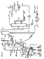
- FIG. 2 A particularly preferred embodiment is described in FIG. 2 where reference numeral 80 identifies a feed control valve in feedstock supply pipe 82.
- Supply pipe 83 (when used) introduces liquid water and/or an additive solution into the feed.
- Heat exchanger 81 in supply pipe 82 acts as a feed preheater, whereby preheated feed material may be delivered to the bottom of a riser type reactor 91.
- Catalyst is delivered to the reactor through catalyst standpipe 86, the flow of catalyst being regulated by a control valve 87 and suitable automatic control equipment (not shown) with which persons skilled in the art of designing and operating riser type cracking units are familiar.
- the reactor is equipped with a disengagement vessel 92 similar to the disengagement vessel 3 of the reactor shown in FIG. 1. Catalyst departs disengagement vessel 92 through stripper 94. Spent catalyst passes from stripper 94 to regenerator 101 via spent catalyst transfer pipe 97 having a slide valve 98 for controlling flow.
- a sidestream of catalyst is passed to distributor 310 through line 326. That portion passing through the magnetic field is returned to line 97 through a line not shown in the figure.
- Regenerator 101 is divided into upper chamber 102 and lower chamber 103 by a divider panel 104 intermediate the upper and lower ends of the regenerator vessel.
- the spent catalyst from transfer pipe 97 enters upper chamber 102 in which the catalyst is partially regenerated.
- a funnel-like collector 106 having a bias-cut upper edge receives partially regenerated catalyst from the upper surface to the dense phase of catalyst in upper chamber 102 and delivers it, via drop let 107 having an outlet 110, beneath the upper surface of the dense phase of catalyst in lower chamber 103.
- an external drop leg instead of internal catalyst drop leg 107, one may use an external drop leg. Valve means in such external drop leg can control the residence time and flow rate in and between the upper and lower chambers. Make up catalyst and/or catalyst or regenerator additives may be added to the upper chamber 102 and/or the lower chamber 103 through addition lines 99 and 100 respectively.
- Air is supplied to the regenerator through an air supply pipe 113. A portion of the air travels through a branch supply pipe 114 to bayonet 115 which extends upwardly into the interior of plenum 111 along its central axis. Catalyst in chamber 103 has access to the space within plenum 111 between its walls and bayonet 115. A smaller bayonet (not shown) in the aforementioned space fluffs the catalyst and urges it upwardly toward a horizontally arranged ring distributor (not shown) adjacent the open top of plenum 111 where it opens into chamber 103.
- air supply pipe 113 may be heated in air heater 117 and is then introduced into inlet 118 of the ring distributor, which may be provided with holes, nozzles or other apertures which produce an upward flow of gas to fluidize the partially regenerated catalyst in chamber 103.
- the air in chamber 103 completes the regeneration of the partially regenerated catalyst received via drop leg 107.
- the amount of air supplied is sufficient so that the resultant combustion gases are still able to support combustion upon reaching the top of chamber 103 and entering chamber 102.
- Drop leg 107 extends through an enlarged aperture in panel 104, to which is secured a gas distributor 120 which is concentric with and surrounds a drop leg.
- Combustion supporting gases from chamber 103 which have been partially depleted, are introduced via gas distributor 120 into upper regenerator chamber 102 where they contact incoming coked catalyst from coked catalyst transfer pipe 97.
- Apertured probes 121 in gas distributor 120 assist in achieving a uniform distribution of the partially depleted combustion supporting gas into upper chamber 102.
- Supplemental air or cooling fluids may be introduced into upper chamber 102 through a supply pipe 122, which may also discharge through gas distributor 120.
- regenerated catalyst is returned to riser 91 for contact with additional fresh feed.
- the division of the regenerator into upper and lower regeneration chambers 102 and 103 not only smooths out variations in catalyst regenerator residence time but is also uniquely of assistance in restricting the quantity of regeneration heat which is imparted to the fresh feed while yielding a regenerated catalyst with low levels of coke for return to the riser.
- the vapor products from disengagement vessel 92 may be processed in any convenient manner such as by discharge through vapor line 131 to fractionator 132.
- Fractionator 132 includes a bottoms outlet 133, side outlet 134, flush oil stripper 135, and stripper bottom line 136 connected to pump 137 for discharging flush oil.
- Overhead product from stripper 135 returns to fractionator 132 via line 138.
- the main overhead discharge line 139 of the fractionator is connected to an overhead receiver 142 having a bottoms line 143 feeding into pump 144 for discharging gasoline product. A portion of this product may be returned to the fractionator via recirculation line 145, the flow being controlled by valve 146.
- the receiver 142 also includes a water receiver 147 and a water discharge line 148.
- the gas outlet 150 of the overhead receiver discharges a stream which is mainly below C5, but containing some C5, C6 and C7 material. If desired, the C5 and above material in the gas stream may be separated by compression cooling and fractionation, and recycled to receiver 142.
- the oxidizing gas, such as air, introduced into regeneration zone 103 through line 114 may be mixed with a cooling spray of water from a conduit 109.
- the mixture of oxidizing gas and atomized water flows through bayonet 115 and thus into the lower bed of catalyst particles.
- the apertures in distributor 120 are large enough so that the upwardly flowing gas readily passes into zone 102. However, the perforations are sized so that the pressure difference between the upper and lower zones prevents catalyst particles from passing downwardly through the distributor.
- the bayonet 115 and distributor are similarly sized. Gases exiting the regenerator comprise combustion products, nitrogen, steam formed by combustion reactions and/or from vaporizing water added to the regenerator, and oxides or sulfur and other trace elements. These gases are separated from suspended catalyst particles by a cyclone separator (not shown) and then pass out of the regenerator through discharge conduit 123.
- regenerators of the type shown in FIGS. 1 and 2 which nave countercurrent flow and are well-suited for producing combustion product gases having a low ratio of CO2 to CO, which helps lower regeneration temperatures in the presence of high carbon levels.
- FIG. 3 discloses a schematic representation of the Rare Earth Roller Magnetic Separator ("RERMS") suitable for this invention. Shown are: a distributor 310, an electrostatic conductive conveyor belt 320, roller distribution point 330, magnetic roller 340, an isolation box 350 (preferably at a negative pressure to avoid dust), divider walls 352, 354, 356 and 358, transverse belts 361, 363 and 365, collection bins 362, 364 and 366, and particulate stream 370.
- RERMS Rare Earth Roller Magnetic Separator
- the stream of particles 370 of for example catalyst or sorbent, having an average particle size in the range 20 to 150 microns is distributed by spreader 310 uniformly over conveyor belt 350 to a thickness determined by metering out so many kg. per cm. per hour.
- the preferred range generally of pounds per inch per hour is anywhere from 1/2 to 20, (0.09 to 3.6 kg/cm/hr) and preferably in the range of about 2 to 10 lbs/in/hr (0.36 to 1.8 kg/cm/hr).
- Conveyor belt 330 moves at a linear velocity, for example, in the range of about 50 to 500 feet (15 to 152 m.) per minute, and preferably 80 to 300 (24 to 91 m.) feet per minute, but is adjusted so as to get a distribution after the roller distribution point 330 in isolation box 320.
- isolation box 350 preferably under a reduced pressure to avoid dust problems, there are a series of transverse belts 361, 363 and 365.
- Each belt has divider walls such as divider walls 352, 354, 356 and 358 to prevent transverse mixing of particulates from one belt to the other, and to ensure cleaner cut of the distribution created by belt 320 after distribution point 330.
- Each belt transports particulates in a direction that is transverse to that direction established by conveyor belt 320.
- Each belt can empty for example into a particular collection bin. Examples of collection bins are 362, 364 and 366. More or less transverse belts may be used. However, it has been found particularly advantageous to increase the number of belts so as to take advantage of the distribution of particulates produced after the distribution point 330. Preferably there are at least two such belts employed.
- Transverse belt 361 and bin 362 could be simply a bin.
- one or more transverse belts can themselves be RERMS and instead, for example, having collection bins at the end of these belts there is still another transverse belt such as transverse belt 320.
- transverse belt 320 can be recycled.
- recycle is a continuous process, wherein the contents of for example bin 362 is recycled back to distributor 310.
- at least two cuts must be established before each recycle begins to optimally produce a cumulatively significant difference in metals level and corresponding activity or adsorbtivity.
- the adverse impact on separation efficiency due to differences in inertial forces is preferably taken into account by means of a separation by a non-magnetic separation prior to subjecting a particulate stream to a RERMS.
- Such initial separation based primarily on size tends to improve later separations in a RERMS, all other factors remaining constant.
- a carbometallic feed with an API° gravity of 15, is introduced at a temperature of about 250°F (121°C.) at a rate of 30,340 B/D (3428 tonne/day) into the bottom zone of a vented riser reactor where it is mixed with lift gas and a zeolite containing catalyst at a temperature of about 1320°F. (715°C.).
- the catalyst to oil ratio is about 8:1.
- the carbometallic feed has a heavy metal content of about 7 parts per million of nickel equivalents, which is comprised of about 5 ppm nickel and about 9 ppm vanadium. This feed has a sulfur content of about 2.6% and a Ramsbottom carbon content of 3.9%.
- the temperature at the reactor effluent is about 975°F (523°C), and the pressure is about 30 psia (207 kPa).
- the catalyst containing about 1.27% by weight of coke and about 0.01% sulfur is removed from the reactor where it is contacted with steam at a temperature of about 1000°F (537°C.) to remove volatiles adsorbed onto the catalyst.
- This spent and stripped catalyst is then introduced into the upper zone of a two-stage regenerator as shown in Fig. 1.
- Each regenerator zone contains about 200 tons (181 tonnes) of catalyst for a total catalyst inventory of about 400 tons (362 tonnes). Air is introduced into the lower zone to burn off remaining carbon, and produces mainly CO2, with very little CO being formed at a temperature of about 1330°F (721°C).
- Air is also introduced into the upper zone together with flue gases from the lower zone.
- the upper zone produced more CO2 and CO at a temperature of about 1330°F (721°C.).
- the regenerator flue gases contain CO2 and CO in a mol ratio of 4.
- the catalyst removed from the lower zone recycled to the reactor riser contains about 0.05% coke by weight.
- a side stream of regenerated catalyst having a MAT relative activity of 20 and a total heavy metal content of 3,200 ppm Nickel equivalents is withdrawn for magnetic separation, and the remainder of the regenerated catalyst is returned to the reactor.
- Non-magnetic fraction #1 representing 25 wt.% of feed contains 2800 ppm of nickel equivalents, a surface area of 108 m2/gm and a MAT relative activity of 30.
- This fraction is sent to chemical reactivation processing for return to the unit.
- Magnetic faction #3 representing 24 wt.% contains 3300 ppm of nickel equivalents, a surface area of 80 m2/gm and a MAT relative activity of 20 is sent to disposal.
- This rare earth roller permanent magnet separator has a magnetic strength of 16,000 gauss, with high gradient as high as 3MM m ⁇ 1 and is a new design in which the separator roll is a roll consisting of disks of Sm-Co, or Nb-Fe-B permanent magnets interleaved with mild steel disks.
- the most favorable ratio of the widths of the magnet and of the steel insert is 4:1. Mild steel insert given the most satisfactory results and special steels usually do not improve the performance of the separator.
- the magnet in this configuration generates magnetic induction up to 1.6T Tessla on the surface of the roll and field gradients of the order of 300T m ⁇ 1 (Tessla per meter).
- the roll is covered by a thin belt supported by a second idler roll.
- a hopper which collects the discharging material while adjustable splitters divert the different fractions into collection pans placed beneath the hopper.
- the side stream of regenerated catalyst is sent to an Eriez Magnetics High Gradient Magnetic Separator HGMS, in a magnetic field of 20,000 Gauss.
- HGMS Erie Magnetics High Gradient Magnetic Separator
- 3% of magnetic regenerated catalyst was recovered with a metals equivalent of 4200, and a 97% non-magnetic fraction with a 2600 metal equivalents.
- Example #1 Under similar process operating conditions a new process modifications was introduced utilizing a conducting carrier belt so as to eliminate electrostatic charge, and thus avoiding the losses reported in Example #1 due to electrostatic effects.
- Slip stream regenerated catalyst from the regenerator was passed over a roll and three cuts made, a two repasses non magnetic portion, a mid cut portion, and magnetic portion subjected to four repasses.
- Table 1 shows the results of this operation. TABLE 1 Catalyst Regenerated RCC Catalyst Non Mag Mid Cut Mag Yield % 11 39 51 Surface Area m2/gm 97 94 84 % C 0.07 0.06 0.05 Nickel Equiv. 2700 2800 3400
- a carbometallic oil feed with an °API gravity of 16.1 is introduced at a temperature of 268°F (131°C.), at a rate of 31,900 B/D (3605 tonnex/day) into the bottom zone of a vented riser reactor where it is mixed with lift gas and zeolite containing catalyst FOC-90 at a temperature of about 1332°F (722°C.) and exiting the reactor at 975°F (523°C.).
- the catalyst to oil ratio is 7.5/1. and the total pressure 30 psia (207 kPa).
- This feed has a heavy metals content of 8 ppm of nickel equivalents (excluding iron) which is composed of 6 ppm of nickel and 8 ppm of vanadium.
- the feed has a sulfur content of 2.6 wt. % and a Ramsbottom (siminlar to Conradson) Carbon of 3.9 wt. %.
- the spent catalyst contains 1.35 wt. % coke and the regenerated catalyst has a surface area of 93 m2/gm.
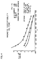
- a side stream of spent catalyst having a surface area of 94 m2/gm and a nickel equivalent content including iron of 3150 ppm is withdrawn before regeneration, and subjected to magnetic separation. See Fig. 4.
- the withdrawn catlyst is split into three fraction, 23 wt. % of now magnetic catalyst with a surface area of 107 m2 /gm. and a metals equivalent of 2700 and recycled back to the unit.
- 40 wt. % of mid cut catalyst is also withdrawn and regenerated and subjected to chemical reactivation. Its metal equivalent is 3070.
- 37 wt. % of the catalyst is removed as magnetic product after 5 repasses and disposed of. This material has a surface area of 83 m2 /gm. and a metals equivalent of 3700
- the upper regenerator temperature was at 1533°F (834°C.) and conversion to 430°F (221°C) minus was 23.2 vol. %.
- Gasoline yield was 8.8 vol. % and 430-630°F (221-332°C.) vol. % was 20.7%.
- the regenerated side stream was taken to an RERPMS for splitting into similar fractions.
- the regenerated Akr CAT contained 7900 ppm of iron, 3030 ppm of nickel, and 10,200 ppm of vanadium.
- Table III shows the results obtained with this method of separation.
- Regenerated Non Mag ART CAT Mid Cut ART Mag Process % yield 31 51 37 spread Surface area m2/gm 5 5 2 between % C 0.12 0.20 0.46 NM and M Cut ppm Ni 2700 3200 3700 1000 ppm Fe 6400 7300 10400 4000 ppm V 7800 9600 14300 6500 Ni Equiv. 5200 6200 8100 11500
- Non-magnetic ART CAT is recycled to the ART unit, the mid cut can be sent for chemical clean up to remove metals and returned to the limit, and the high magnetic fraction treated separately for metals recovery and discarded.
- the RERPHS-Eriez unit can also be operated so as to only produce two cuts, a low metals fraction for recycle, and a high metals fraction for disposal or metals recovery. Note that there is a 1.15 wt. % metal difference between non magnetic and magnetic fractions.
- This example is a demonstration of magnetic separation employing increasing magnetic field strength as one goes from one roller magnetic separator to another.
- 100 lbs. (45 kg.) of equilibrium cracking catalyst having a metals level of 2500 ppm nickel; 7000 ppm vanadium; and 8900 ppm iron with a particle size in the range of 53 to 212 microns with an average particle size of 114 microns was separated by passing at a rate of 10 lbs/inch (1.79 kg/cm) of belt width/hour with the belt moving at a rate over the ferrite rolls of 129 feet (39 m.) per minute, and over the rare earth magnetic rolls, 308 feet (94 m) per minute. On each pass over a roller, a magnetic and a non-magnetic portion resulted. It was the non-magnetic portion from each separation which was in turn used in the subsequent passage over the next magnetic roll.
Landscapes
- Chemical & Material Sciences (AREA)
- Oil, Petroleum & Natural Gas (AREA)
- Engineering & Computer Science (AREA)
- Chemical Kinetics & Catalysis (AREA)
- General Chemical & Material Sciences (AREA)
- Organic Chemistry (AREA)
- Catalysts (AREA)
- Production Of Liquid Hydrocarbon Mixture For Refining Petroleum (AREA)
- Organic Low-Molecular-Weight Compounds And Preparation Thereof (AREA)
Claims (10)
- Verfahren zur Umwandlung von mit Metall verunreinigten Chargen schwerer Kohlenwasserstoffe in leichtere Produkte, das das Zusammenbringen der mit Metall verunreinigten Charge mit einem fluidisierten, teilchenförmigen katalytischen Material in einem Reaktor unter Bedingungen, bei denen sich Kohlenstoff und Metall auf dem teilchenförmigen Material bei gleichzeitigem Cracken der Charge zur Bereitstellung der leichteren Produkte ablagern, die getrennte Gewinnung der leichteren Produkte und eines Stromes des verwendeten mit Kohlenstoff- und Metallablagerungen verunreinigten teilchenförmigen Materials aus dem Reaktor, das Durchleiten des Stromes von verwendetem teilchenförmigen Materials in eine Regenerationszone, in der vor dem Rückführen eines Stromes von regenerierten Teilchen in den Reaktor Kohlenstoff von dem teilchenförmigen Material entfernt wird, umfaßt und worin ein Teil des teilchenförmigen Materials aus dem Kreislauf entnommen wird und einem magnetischen Trennverfahren unterworfen wird, bei dem die Teilchen in einen ersten Strom, der Teilchen mit einer relativ hohen katalytischen Aktivität, einer niedrigen magnetischen Suszeptibilität und einem niedrigen Metallgehalt enthält, und in einen zweiten Strom von Teilchen mit einer relativ niedrigen katalytischen Aktivität, einer hohen magnetischen Suszeptibilität und einem hohen Metallgehalt getrennt werden, wobei nur der erste Strom oder nur ein Teil davon in den Reaktor zurückgeführt werden, dadurch gekennzeichnet, daß das magnetische Trennverfahren durch(a) Streuen der zu trennenden Teilchen auf ein Laufband, das mindestens einen Magneten passiert, der eine Feldstärke von mindestens 1 Kilogauss, gemessen bei einem Abstand von 0,0076 cm von der Oberfläche des Magneten, aufweist, und(b) Bewegungssteuerung des Bandes, um den ersten Strom, der die Teilchen mit relativ hoher katalytischer Aktivität, niedriger magnetischer Suszeptibilität und geringem Metallgehalt enthält, und von welchem mindestens ein Teil in den Reaktor zurückgeführt wird, und mindestens einen weiteren Strom, der die Teilchen mit relativ niedriger katalytischen Aktivität, hoher magnetischer Suzceptibilität und hohem Metallgehalt enthält, von dem Band zu entfernen, und wobei der letztere Strom oder Ströme aus dem Verfahren entfernt wird bzw. werden,durchgeführt wird.
- Sorptionsverfahren zur Entfernung von Metallen aus Metall-verunreinigten Kohlenwasserstoffchargen, das das Zusammenbringen der Metall-verunreinigten Charge mit einem fluidisierten, teilchenförmigen Sorptionsmaterial in einem Reaktor unter Bedingungen, bei denen sich Kohlenstoff und Metall auf dem teilchenförmigen Material ablagert, die getrennte Gewinnung eines reduziertes Metall enthaltenden Kohlenwasserstoffprodukts und einen Strom von mit Kohlenstoff- und Metallablagerungen verunreinigtem verwendeten teilchenförmigen Materials aus dem Reaktor, das Durchleiten des Stromes von verwendetem teilchenförmigen Materials in eine Regenerationszone, in der vor dem Rückfuhren eines Stromes von regenerierten Teilchen in den Reaktor Kohlenstoff von dem teilchenförmigen Material entfernt wird, umfaßt und worin ein Teil des teilchenförmigen Materials aus dem Kreislauf entnommen wird und einem magnetischen Trennverfahren unterworfen wird, bei dem die Teilchen in einen ersten Strom, der Teilchen mit einer relativ hohen Sorptionsaktivität, einer niedrigen magnetischen Suszeptibilität und einem niedrigen Metallgehalt enthält, und in einen zweiten Strom von Teilchen mit einer relativ niedrigen Sorptionsaktivität, einer hohen magnetischen Suszeptibilität und einem hohen Metallgehalt getrennt werden, wobei nur der erste Strom oder nur ein Teil davon in den Reaktor zurückgeführt werden, dadurch gekennzeichnet, daß das magnetische Trennverfahren durch(a) Streuen der zu trennenden Teilchen auf ein Laufband, das mindestens einen Magneten passiert, der eine Feldstärke von mindestens 1 Kilogauss, gemessen bei einem Abstand von 0,0076 cm von der Oberfläche des Magneten aufweist, und(b) Bewegungssteuerung des Bandes, um den ersten Strom, der die Teilchen mit relativ hoher Sorptionsaktivität, niedriger magnetischer Suszeptibilität und geringem Metallgehalt enthält, und von welchem mindestens ein Teil in den Reaktor zurückgeführt wird, und mindestens einen weiteren Strom, der die Teilchen mit relativ niedriger Sorptionsaktivität, hoher magnetischer Suszeptibilität und hohem Metallgehalt von dem Band getrennt zu entfernen, und wobei der letztere Strom oder Ströme aus dem Verfahren entfernt wird bzw. werden,durchgeführt wird.
- Verfahren nach Anspruch 1 oder 2, worin das in den Reaktor eingebrachte teilchenförmige Material 1000 ppm bis 30000 ppm Nickeläquivalente von Schwermetall(en) und/oder einer Metallverbindung (Metallverbindungen), gemessen auf einem regenerierten Gleichgewichtskatalysator, umfaßt und worin das Laufband leitfähig ist, um eine elektrostatische Ladung auf den zurückgeführten Teilchen zu verhindern.
- Verfahren nach Anspruch 1 oder 3, worin das in den Reaktor eingebrachte teilchenförmige Material einen Zeolith-Molekularsiebkatalysator, der mindestens etwa 5 Gew.-% des Siebs enthält, umfaßt.
- Verfahren nach einem der Ansprüche 1 bis 4, worin die Charge 650°F+ - (343°C+ -) Material enthält, das im wesentlichen nicht mit Wasserstoff behandelt worden ist und das mindestens etwa 5,5 ppm Nickeläquivalente von Schwermetall(en), vorhanden in Form von elementarem Metall (elementaren Metallen) und/oder einer Metallverbindung (Metallverbindungen), enthält, wobei die Charge mit dem teilchenförmigen Material zur Bildung einer resultierenden Suspension aus teilchenförmigem Material, Charge und gasförmigem Material zusammengebracht wird, worin das Verhältnis des Partialdrucks des gasförmigen Materials bezogen auf den Partialdruck der Charge im Bereich von 0,25 bis 4,0 ist und die Dampfverweilzeit der Charge und der Produkte im Reaktor im Bereich von 0,5 bis 3 Sekunden ist.
- Verfahren nach einem der Ansprüche 1 bis 5, worin das aus dem Reaktor entfernte teilchenförmige Material vor dem Durchleiten durch das magnetische Feld einer reduzierenden Atmosphäre unterworfen wird.
- Verfahren nach einem der Ansprüche 1 bis 6, worin mindestens ein Teil des entfernten teilchenförmigen Materials durch das magnetische Feld als im wesentlichen fluidisierbare trockene Teilchen durchgeleitet wird und worin die magnetische Feldstärke im Bereich von 1 KG bis 25 KG ist.
- Verfahren nach einem der Ansprüche 1 bis 7, worin das entfernte teilchenförmige Material durch eine Reihe von magnetischen Trenneinrichtungen durchgeleitet wird, die das Material in mindestens zwei Ströme teilen, wobei der eine Strom mindestens 20% Punkte von MAT-relativer Aktivität im Überschuß zu der MAT-relativen Aktivität des anderen Stroms oder der anderen Ströme aufweist.
- Verfahren nach einem der Ansprüche 1 bis 8, worin die magnetische Trenneinrichtung einen Permanentmagneten aus einer Neodym-Bor-Eisen-Legierung oder einen Permanentmagneten aus Samarium/Cobalt umfaßt und worin das teilchenförmige Material vor der magnetischen Trennung auf weniger als 93,4°C (200°F) abgekühlt wird und worin das Laufband leitfähig ist, um eine elektrostatische Ladung auf den entfernten Teilchen zu verhindern.
- Verfahren nach einem der Ansprüche 1 bis 9, worin sich das Band mit einer Geschwindigkeit von 1 bis 1000 Fuß/Minute (0,30 bis 300 m/min) über eine Rolle bewegt.
Applications Claiming Priority (3)
| Application Number | Priority Date | Filing Date | Title |
|---|---|---|---|
| US332079 | 1989-04-03 | ||
| US07/332,079 US5147527A (en) | 1989-04-03 | 1989-04-03 | Magnetic separation of high metals containing catalysts into low, intermediate and high metals and activity catalyst |
| PCT/US1990/001583 WO1990012075A1 (en) | 1989-04-03 | 1990-03-23 | Magnetic separation into low, intermediate and high metals and activity catalyst |
Publications (2)
| Publication Number | Publication Date |
|---|---|
| EP0466735A1 EP0466735A1 (de) | 1992-01-22 |
| EP0466735B1 true EP0466735B1 (de) | 1994-04-20 |
Family
ID=23296647
Family Applications (1)
| Application Number | Title | Priority Date | Filing Date |
|---|---|---|---|
| EP90905331A Expired - Lifetime EP0466735B1 (de) | 1989-04-03 | 1990-03-23 | Magnetische trennung in niedrig-, intermediär- und hochmetall und aktiver katalysator |
Country Status (10)
| Country | Link |
|---|---|
| US (1) | US5147527A (de) |
| EP (1) | EP0466735B1 (de) |
| JP (1) | JPH0723476B2 (de) |
| KR (1) | KR950002345B1 (de) |
| AU (2) | AU632111B2 (de) |
| BR (1) | BR9006984A (de) |
| CA (1) | CA2042388C (de) |
| DE (1) | DE69008349T2 (de) |
| ES (1) | ES2078828B1 (de) |
| WO (1) | WO1990012075A1 (de) |
Families Citing this family (34)
| Publication number | Priority date | Publication date | Assignee | Title |
|---|---|---|---|---|
| US5190635A (en) * | 1989-04-03 | 1993-03-02 | Ashland Oil, Inc. | Superparamagnetic formation of FCC catalyst provides means of separation of old equilibrium fluid cracking catalyst |
| US5106486A (en) * | 1990-02-09 | 1992-04-21 | Ashland Oil, Inc. | Addition of magnetically active moieties for magnetic beneficiation of particulates in fluid bed hydrocarbon processing |
| US5198098A (en) * | 1990-10-19 | 1993-03-30 | Ashland Oil, Inc. | Magnetic separation of old from new equilibrium particles by means of manganese addition |
| US5171424A (en) * | 1990-10-22 | 1992-12-15 | Ashland Oil, Inc. | Magnetic separation of old from new cracking catalyst by means of heavy rare earth "magnetic hooks" |
| US5393412A (en) * | 1991-05-03 | 1995-02-28 | Ashland Oil, Inc. | Combination magnetic separation, classification and attrition process for renewing and recovering particulates |
| US5250482A (en) * | 1992-08-20 | 1993-10-05 | University Of Chicago | Process for magnetic beneficiating petroleum cracking catalyst |
| CA2116514A1 (en) * | 1993-03-02 | 1994-09-03 | Takashi Ino | Process for the fluid catalytic cracking of heavy fraction oils |
| BE1007049A3 (nl) * | 1993-05-05 | 1995-02-28 | Dsm Nv | Werkwijze voor het verwijderen van kwik. |
| CN1120875C (zh) * | 1995-01-13 | 2003-09-10 | 爱什股份有限公司 | 烃转化催化添加剂及其方法 |
| US6059959A (en) * | 1996-02-08 | 2000-05-09 | Kellogg Brown & Root, Inc. | Varying carbon on catalyst to magnetically separate high metals catalyst |
| US5985134A (en) * | 1997-01-12 | 1999-11-16 | M.W. Kellogg Company | Startup of magnetic separation process in an FCC unit |
| US5958219A (en) * | 1997-01-12 | 1999-09-28 | The M. W. Kellogg Company | Metals passivation by magnetic treatment to permit higher metals levels on FCC catalyst |
| US6041942A (en) * | 1997-01-12 | 2000-03-28 | Kellogg Brown & Root, Inc. | Magnetic catalyst separation using stacked magnets |
| US5972208A (en) * | 1997-07-11 | 1999-10-26 | The M. W. Kellogg Company | FCC metals passivation additives applied to catalyst |
| US6099721A (en) * | 1998-02-12 | 2000-08-08 | The M.W. Kellogg Company | Use of magnetic separation to remove non-magnetic, particles from FCC catalyst |
| WO2001094009A1 (en) | 2000-06-08 | 2001-12-13 | Japan Energy Corporation | Method for preparing catalyst for use in hydro-refining and method for recovering metal |
| NO20014148A (no) * | 2001-08-27 | 2003-02-03 | Elkem As | Fremgangsmåte for fjerning av forurensinger fra silisiuminneholdende residuer |
| US6433205B1 (en) | 2002-01-15 | 2002-08-13 | Dow Corning Corporation | Magnetic separation for silicon-containing materials |
| JP4918680B2 (ja) * | 2003-06-09 | 2012-04-18 | ダウ・コーニング・コーポレイション | 磁気選別機装置 |
| WO2005081990A2 (en) * | 2004-02-26 | 2005-09-09 | Metal Alloy Reclaimers, Inc. Ii | Discarded fcc equilibrium catalyst through reclamation |
| US20060081504A1 (en) * | 2004-10-07 | 2006-04-20 | Rineco Chemical Industries, Inc. | Systems and methods for processing waste materials |
| US7341155B2 (en) * | 2004-10-07 | 2008-03-11 | Rineco Chemical Industries, Inc. | Systems and methods for processing waste materials |
| FR2895413B1 (fr) * | 2005-12-27 | 2011-07-29 | Alstom Technology Ltd | Installation de conversion d'hydrocarbures petroliers a installation de combustion integree comprenant une capture du dioxyde de carbone |
| US7692046B2 (en) | 2007-06-21 | 2010-04-06 | Exxonmobil Chemical Patents Inc. | Heterogeneous arylalkyl oxidation promoter |
| US10279328B2 (en) * | 2009-02-27 | 2019-05-07 | Basf Corporation | Process for the preparation of metal-carbon containing bodies |
| US8216532B1 (en) | 2011-06-17 | 2012-07-10 | Vierheilig Albert A | Methods of recovering rare earth elements |
| JP6460879B2 (ja) * | 2015-03-30 | 2019-01-30 | 新日鐵住金株式会社 | タール含有ガス改質用触媒の再生方法 |
| JP6719980B2 (ja) * | 2016-05-17 | 2020-07-08 | 日揮触媒化成株式会社 | 鉄堆積流動接触分解用触媒の再活性化方法、再活性化装置、流動接触分解方法 |
| JP6808200B2 (ja) | 2016-12-08 | 2021-01-06 | 株式会社カワノラボ | 粒子分析装置、及び粒子分析方法 |
| CN110628454B (zh) * | 2018-06-21 | 2021-11-05 | 国家能源投资集团有限责任公司 | 费托合成系统及分离费托合成油气产物中催化剂细粉的方法 |
| CN109705902A (zh) * | 2018-12-18 | 2019-05-03 | 洛阳瑞华新能源技术发展有限公司 | 用磁性过滤器净化物料的烃悬浮床加氢反应方法 |
| CN116948691B (zh) * | 2022-04-20 | 2025-04-01 | 中国石油化工股份有限公司 | 一种汽油加氢改质装置及方法 |
| CN116948689B (zh) * | 2022-04-20 | 2025-04-01 | 中国石油化工股份有限公司 | 一种劣质柴油加氢处理方法及装置 |
| CN116948681B (zh) * | 2022-04-20 | 2025-04-01 | 中国石油化工股份有限公司 | 一种全馏分汽油加氢装置及方法 |
Family Cites Families (30)
| Publication number | Priority date | Publication date | Assignee | Title |
|---|---|---|---|---|
| US2160874A (en) * | 1937-01-05 | 1939-06-06 | Sonneborn Sons Inc L | Process of regenerating a bauxite adsorbent |
| US2490774A (en) * | 1947-11-29 | 1949-12-13 | Houdry Process Corp | Moving bed hydrocarbon conversion system |
| US2694622A (en) * | 1948-07-02 | 1954-11-16 | Union Oil Co | Hydrocarbon refining apparatus |
| US2607492A (en) * | 1949-01-27 | 1952-08-19 | Standard Oil Dev Co | Apparatus for removing iron impurities from fluid streams |
| US2688403A (en) * | 1951-01-08 | 1954-09-07 | Sundstrand Magnetic Products C | Magnetic separator |
| US2775607A (en) * | 1952-11-17 | 1956-12-25 | Rheinpreussen Ag | Reactivation of catalysts |
| US2760638A (en) * | 1954-05-06 | 1956-08-28 | Phillips Petroleum Co | Magnetic separator |
| US2956004A (en) * | 1958-03-25 | 1960-10-11 | Standard Oil Co | Removing metal contaminants from feeds |
| GB940958A (en) * | 1960-08-17 | 1963-11-06 | British Petroleum Co | Improvements relating to the treatment of catalysts |
| US3901795A (en) * | 1972-11-10 | 1975-08-26 | Continental Can Co | Method and apparatus for separating magnetic and non-magnetic substances |
| US4292171A (en) * | 1976-11-01 | 1981-09-29 | Exxon Research & Engineering Co. | Magnetically stabilized, fluidized beds |
| US4294688A (en) * | 1976-11-01 | 1981-10-13 | Exxon Research & Engineering Co. | Heat transfer in magnetically stabilized, fluidized beds |
| US4167474A (en) * | 1977-06-27 | 1979-09-11 | Uop Inc. | Multiple-stage catalytic reforming with gravity-flowing dissimilar catalyst particles |
| JPS5835638B2 (ja) * | 1979-04-11 | 1983-08-03 | 株式会社神戸製鋼所 | 重質油の熱分解及び還元鉄の製造法 |
| US4259181A (en) * | 1979-04-16 | 1981-03-31 | Cabot Corporation | Stream splitter for spreading particulate material |
| JPS6024831B2 (ja) * | 1979-12-21 | 1985-06-14 | 日石三菱株式会社 | 蒸留残渣を含む重質石油類の接触分解方法 |
| US4359379A (en) * | 1979-12-21 | 1982-11-16 | Nippon Oil Company, Ltd. | Process for fluid catalytic cracking of distillation residual oils |
| US4280896A (en) * | 1979-12-31 | 1981-07-28 | Exxon Research & Engineering Co. | Passivation of cracking catalysts |
| US4332674A (en) * | 1980-07-15 | 1982-06-01 | Dean Robert R | Method and apparatus for cracking residual oils |
| JPS5730787A (en) * | 1980-07-31 | 1982-02-19 | Nippon Oil Co Ltd | Method for catalytic reaction of heavy petroleum oil |
| JPS5730786A (en) * | 1980-07-31 | 1982-02-19 | Nippon Oil Co Ltd | Method for catalytic reaction of heavy petroleum oil |
| US4406773A (en) * | 1981-05-13 | 1983-09-27 | Ashland Oil, Inc. | Magnetic separation of high activity catalyst from low activity catalyst |
| US4541920A (en) * | 1982-09-22 | 1985-09-17 | Exxon Research And Engineering Co. | Composition and reforming process for the operation of a magnetically stabilized fluidized bed |
| FR2542631B1 (fr) * | 1983-03-15 | 1985-07-19 | Eurecat Europ Retrait Catalys | Procede de traitement de particules catalytiques et procede et appareil de transport et de chauffage de materiaux granules |
| DE3313997C2 (de) * | 1983-04-18 | 1986-07-03 | Günter Dipl.-Ing. 2000 Hamburg Kupczik | Fördervorrichtung zum Entfernen von Erdöl und Erdölfraktionen aus Wasser |
| US4729821A (en) * | 1986-11-03 | 1988-03-08 | Board Of Regents, The University Of Texas System | In situ activation of catalysts by applied electrical potentials |
| US4835128A (en) * | 1986-12-04 | 1989-05-30 | Mobil Oil Corporation | Method for reducing the effects of metals on FCC catalysts |
| US4898116A (en) * | 1987-09-14 | 1990-02-06 | Onoda Cement Company, Ltd. | Powder coating booth |
| JPH0677163B2 (ja) * | 1988-08-23 | 1994-09-28 | キヤノン株式会社 | 画像形成装置 |
| JPH0293674A (ja) * | 1988-09-30 | 1990-04-04 | Nippon Kentek Kaisha Ltd | ベルト転写装置 |
-
1989
- 1989-04-03 US US07/332,079 patent/US5147527A/en not_active Expired - Lifetime
-
1990
- 1990-03-23 WO PCT/US1990/001583 patent/WO1990012075A1/en not_active Ceased
- 1990-03-23 DE DE69008349T patent/DE69008349T2/de not_active Expired - Fee Related
- 1990-03-23 EP EP90905331A patent/EP0466735B1/de not_active Expired - Lifetime
- 1990-03-23 JP JP2505285A patent/JPH0723476B2/ja not_active Expired - Fee Related
- 1990-03-23 BR BR909006984A patent/BR9006984A/pt not_active IP Right Cessation
- 1990-03-23 AU AU53454/90A patent/AU632111B2/en not_active Expired - Fee Related
- 1990-03-23 ES ES09050017A patent/ES2078828B1/es not_active Expired - Fee Related
- 1990-03-23 CA CA002042388A patent/CA2042388C/en not_active Expired - Fee Related
- 1990-03-23 KR KR1019900702551A patent/KR950002345B1/ko not_active Expired - Fee Related
-
1993
- 1993-01-29 AU AU32153/93A patent/AU644755B2/en not_active Ceased
Non-Patent Citations (1)
| Title |
|---|
| j. Svoboda: Magnetic Methods for the Treatment of Minerals", 1987, Elsevier, (Amsterdam, NL), see pages 144-149 (cited in the application) * |
Also Published As
| Publication number | Publication date |
|---|---|
| CA2042388C (en) | 1998-09-29 |
| JPH04503373A (ja) | 1992-06-18 |
| AU644755B2 (en) | 1993-12-16 |
| AU632111B2 (en) | 1992-12-17 |
| DE69008349D1 (de) | 1994-05-26 |
| EP0466735A1 (de) | 1992-01-22 |
| DE69008349T2 (de) | 1994-08-04 |
| AU5345490A (en) | 1990-11-05 |
| ES2078828A1 (es) | 1995-12-16 |
| US5147527A (en) | 1992-09-15 |
| ES2078828B1 (es) | 1996-10-16 |
| WO1990012075A1 (en) | 1990-10-18 |
| BR9006984A (pt) | 1991-11-12 |
| JPH0723476B2 (ja) | 1995-03-15 |
| KR950002345B1 (ko) | 1995-03-16 |
| AU3215393A (en) | 1993-03-25 |
| KR920700277A (ko) | 1992-02-19 |
| CA2042388A1 (en) | 1990-10-04 |
Similar Documents
| Publication | Publication Date | Title |
|---|---|---|
| EP0466735B1 (de) | Magnetische trennung in niedrig-, intermediär- und hochmetall und aktiver katalysator | |
| EP0106052B1 (de) | Entmetallisierung und Entkarbonisierung schwerer Rückstandsöl-Einsatzprodukte | |
| US5364827A (en) | Composition comprising magnetically active moieties for magnetic beneficiation of particulates in fluid bed hydrocarbon processing | |
| US3821103A (en) | Conversion of sulfur contaminated hydrocarbons | |
| US6010618A (en) | FCC process with two zone short contact time reaction conduit | |
| US5059302A (en) | Method and apparatus for the fluid catalytic cracking of hydrocarbon feed employing a separable mixture of catalyst and sorbent particles | |
| CA1183826A (en) | Regeneration of catalyst used in the conversion of carbo-metallic containing residual oils | |
| US5196172A (en) | Apparatus for the fluid catalytic cracking of hydrocarbon feed employing a separable mixture of catalyst and sorbent particles | |
| US5230869A (en) | Addition of magnetically active moieties for magnetic beneficiation of particulates in fluid bed hydrocarbon processing | |
| US4230557A (en) | Removal of entrained solids from retorted hydrocarbonaceous vapors | |
| EP0398557A1 (de) | Verfahren und Vorrichtung zum fluidisierten katalytischen Kracken | |
| JPH03503903A (ja) | Fccシステムにおいて小さい触媒粒子を取り出すための改善された方法および装置 | |
| EP0613937A1 (de) | Verfahren für das katalitysche Wirbelschichtspalten von Schwerölen | |
| US2700017A (en) | Method of coking residual hydrocarbons | |
| EP0309244A1 (de) | Regenerierung bei katalytischer Krackung in der Wirbelschicht mit einem Separator für verbrauchten Katalysator | |
| RU2040536C1 (ru) | Способ конверсии нефтяного сырья | |
| US5958219A (en) | Metals passivation by magnetic treatment to permit higher metals levels on FCC catalyst | |
| EP0092059A1 (de) | Regeneration eines Katalysators, der bei der Konversion carbo-metallischer Rückstandsöle verwendet worden ist | |
| WO2015082375A1 (en) | A process for carrying out endothermic, heterogeneously catalyzed reactions | |
| US5985134A (en) | Startup of magnetic separation process in an FCC unit | |
| JPH06116569A (ja) | 重質油の流動接触分解方法 | |
| CA1332165C (en) | Method and apparatus for withdrawal of small catalyst particles in fcc systems | |
| US2941938A (en) | Hydrocarbon conversion process with the recovery of the catalytic fines | |
| KR101250173B1 (ko) | 유동접촉분해촉매의 자기분리방법 |
Legal Events
| Date | Code | Title | Description |
|---|---|---|---|
| PUAI | Public reference made under article 153(3) epc to a published international application that has entered the european phase |
Free format text: ORIGINAL CODE: 0009012 |
|
| 17P | Request for examination filed |
Effective date: 19911019 |
|
| AK | Designated contracting states |
Kind code of ref document: A1 Designated state(s): BE DE FR GB IT NL |
|
| 17Q | First examination report despatched |
Effective date: 19920521 |
|
| GRAA | (expected) grant |
Free format text: ORIGINAL CODE: 0009210 |
|
| AK | Designated contracting states |
Kind code of ref document: B1 Designated state(s): BE DE FR GB IT NL |
|
| REF | Corresponds to: |
Ref document number: 69008349 Country of ref document: DE Date of ref document: 19940526 |
|
| ET | Fr: translation filed | ||
| ITF | It: translation for a ep patent filed | ||
| PLBE | No opposition filed within time limit |
Free format text: ORIGINAL CODE: 0009261 |
|
| STAA | Information on the status of an ep patent application or granted ep patent |
Free format text: STATUS: NO OPPOSITION FILED WITHIN TIME LIMIT |
|
| 26N | No opposition filed | ||
| REG | Reference to a national code |
Ref country code: GB Ref legal event code: IF02 |
|
| PGFP | Annual fee paid to national office [announced via postgrant information from national office to epo] |
Ref country code: GB Payment date: 20050207 Year of fee payment: 16 |
|
| PGFP | Annual fee paid to national office [announced via postgrant information from national office to epo] |
Ref country code: NL Payment date: 20050209 Year of fee payment: 16 |
|
| PGFP | Annual fee paid to national office [announced via postgrant information from national office to epo] |
Ref country code: FR Payment date: 20050302 Year of fee payment: 16 |
|
| PGFP | Annual fee paid to national office [announced via postgrant information from national office to epo] |
Ref country code: DE Payment date: 20050331 Year of fee payment: 16 |
|
| PGFP | Annual fee paid to national office [announced via postgrant information from national office to epo] |
Ref country code: BE Payment date: 20050412 Year of fee payment: 16 |
|
| PG25 | Lapsed in a contracting state [announced via postgrant information from national office to epo] |
Ref country code: GB Free format text: LAPSE BECAUSE OF NON-PAYMENT OF DUE FEES Effective date: 20060323 |
|
| PG25 | Lapsed in a contracting state [announced via postgrant information from national office to epo] |
Ref country code: BE Free format text: LAPSE BECAUSE OF NON-PAYMENT OF DUE FEES Effective date: 20060331 |
|
| PGFP | Annual fee paid to national office [announced via postgrant information from national office to epo] |
Ref country code: IT Payment date: 20060331 Year of fee payment: 17 |
|
| PG25 | Lapsed in a contracting state [announced via postgrant information from national office to epo] |
Ref country code: NL Free format text: LAPSE BECAUSE OF NON-PAYMENT OF DUE FEES Effective date: 20061001 |
|
| PG25 | Lapsed in a contracting state [announced via postgrant information from national office to epo] |
Ref country code: DE Free format text: LAPSE BECAUSE OF NON-PAYMENT OF DUE FEES Effective date: 20061003 |
|
| GBPC | Gb: european patent ceased through non-payment of renewal fee |
Effective date: 20060323 |
|
| NLV4 | Nl: lapsed or anulled due to non-payment of the annual fee |
Effective date: 20061001 |
|
| REG | Reference to a national code |
Ref country code: FR Ref legal event code: ST Effective date: 20061130 |
|
| BERE | Be: lapsed |
Owner name: *ASHLAND OIL INC. Effective date: 20060331 |
|
| PG25 | Lapsed in a contracting state [announced via postgrant information from national office to epo] |
Ref country code: FR Free format text: LAPSE BECAUSE OF NON-PAYMENT OF DUE FEES Effective date: 20060331 |
|
| PG25 | Lapsed in a contracting state [announced via postgrant information from national office to epo] |
Ref country code: IT Free format text: LAPSE BECAUSE OF NON-PAYMENT OF DUE FEES Effective date: 20070323 |