EP0466910B1 - Lentille ultrasonique de haute energie a facettes de montage - Google Patents
Lentille ultrasonique de haute energie a facettes de montage Download PDFInfo
- Publication number
- EP0466910B1 EP0466910B1 EP91904638A EP91904638A EP0466910B1 EP 0466910 B1 EP0466910 B1 EP 0466910B1 EP 91904638 A EP91904638 A EP 91904638A EP 91904638 A EP91904638 A EP 91904638A EP 0466910 B1 EP0466910 B1 EP 0466910B1
- Authority
- EP
- European Patent Office
- Prior art keywords
- ultrasonic device
- transducers
- transducer
- ultrasonic
- curved support
- Prior art date
- Legal status (The legal status is an assumption and is not a legal conclusion. Google has not performed a legal analysis and makes no representation as to the accuracy of the status listed.)
- Expired - Lifetime
Links
- 239000000463 material Substances 0.000 claims description 13
- 230000005540 biological transmission Effects 0.000 claims description 7
- 239000004020 conductor Substances 0.000 claims description 6
- 230000005684 electric field Effects 0.000 claims description 6
- 239000004593 Epoxy Substances 0.000 claims description 5
- XAGFODPZIPBFFR-UHFFFAOYSA-N aluminium Chemical compound [Al] XAGFODPZIPBFFR-UHFFFAOYSA-N 0.000 claims description 4
- 229910052782 aluminium Inorganic materials 0.000 claims description 4
- 238000006243 chemical reaction Methods 0.000 claims description 2
- 239000002482 conductive additive Substances 0.000 claims description 2
- 239000004411 aluminium Substances 0.000 claims 2
- 238000001727 in vivo Methods 0.000 claims 2
- 239000013078 crystal Substances 0.000 description 5
- 238000003491 array Methods 0.000 description 3
- 239000012530 fluid Substances 0.000 description 3
- PEDCQBHIVMGVHV-UHFFFAOYSA-N Glycerine Chemical compound OCC(O)CO PEDCQBHIVMGVHV-UHFFFAOYSA-N 0.000 description 2
- 239000000919 ceramic Substances 0.000 description 2
- 230000002093 peripheral effect Effects 0.000 description 2
- 239000004575 stone Substances 0.000 description 2
- 238000002604 ultrasonography Methods 0.000 description 2
- XLYOFNOQVPJJNP-UHFFFAOYSA-N water Substances O XLYOFNOQVPJJNP-UHFFFAOYSA-N 0.000 description 2
- 239000004677 Nylon Substances 0.000 description 1
- 201000009310 astigmatism Diseases 0.000 description 1
- 230000015556 catabolic process Effects 0.000 description 1
- 230000015271 coagulation Effects 0.000 description 1
- 238000005345 coagulation Methods 0.000 description 1
- 239000012141 concentrate Substances 0.000 description 1
- 238000010276 construction Methods 0.000 description 1
- 238000007872 degassing Methods 0.000 description 1
- 238000007599 discharging Methods 0.000 description 1
- 239000002305 electric material Substances 0.000 description 1
- 230000003628 erosive effect Effects 0.000 description 1
- 239000000284 extract Substances 0.000 description 1
- 238000010304 firing Methods 0.000 description 1
- 235000011187 glycerol Nutrition 0.000 description 1
- 238000003384 imaging method Methods 0.000 description 1
- 238000009413 insulation Methods 0.000 description 1
- 239000012212 insulator Substances 0.000 description 1
- 239000012528 membrane Substances 0.000 description 1
- 229920001778 nylon Polymers 0.000 description 1
- 239000004033 plastic Substances 0.000 description 1
- 229920003023 plastic Polymers 0.000 description 1
- 239000000523 sample Substances 0.000 description 1
- 229910052709 silver Inorganic materials 0.000 description 1
- 239000004332 silver Substances 0.000 description 1
- 238000009211 ultrasonic lithotripsy Methods 0.000 description 1
Images

Classifications
-
- G—PHYSICS
- G10—MUSICAL INSTRUMENTS; ACOUSTICS
- G10K—SOUND-PRODUCING DEVICES; METHODS OR DEVICES FOR PROTECTING AGAINST, OR FOR DAMPING, NOISE OR OTHER ACOUSTIC WAVES IN GENERAL; ACOUSTICS NOT OTHERWISE PROVIDED FOR
- G10K11/00—Methods or devices for transmitting, conducting or directing sound in general; Methods or devices for protecting against, or for damping, noise or other acoustic waves in general
- G10K11/18—Methods or devices for transmitting, conducting or directing sound
- G10K11/26—Sound-focusing or directing, e.g. scanning
- G10K11/32—Sound-focusing or directing, e.g. scanning characterised by the shape of the source
-
- B—PERFORMING OPERATIONS; TRANSPORTING
- B06—GENERATING OR TRANSMITTING MECHANICAL VIBRATIONS IN GENERAL
- B06B—METHODS OR APPARATUS FOR GENERATING OR TRANSMITTING MECHANICAL VIBRATIONS OF INFRASONIC, SONIC, OR ULTRASONIC FREQUENCY, e.g. FOR PERFORMING MECHANICAL WORK IN GENERAL
- B06B1/00—Methods or apparatus for generating mechanical vibrations of infrasonic, sonic, or ultrasonic frequency
- B06B1/02—Methods or apparatus for generating mechanical vibrations of infrasonic, sonic, or ultrasonic frequency making use of electrical energy
- B06B1/06—Methods or apparatus for generating mechanical vibrations of infrasonic, sonic, or ultrasonic frequency making use of electrical energy operating with piezoelectric effect or with electrostriction
- B06B1/0607—Methods or apparatus for generating mechanical vibrations of infrasonic, sonic, or ultrasonic frequency making use of electrical energy operating with piezoelectric effect or with electrostriction using multiple elements
- B06B1/0622—Methods or apparatus for generating mechanical vibrations of infrasonic, sonic, or ultrasonic frequency making use of electrical energy operating with piezoelectric effect or with electrostriction using multiple elements on one surface
-
- G—PHYSICS
- G10—MUSICAL INSTRUMENTS; ACOUSTICS
- G10K—SOUND-PRODUCING DEVICES; METHODS OR DEVICES FOR PROTECTING AGAINST, OR FOR DAMPING, NOISE OR OTHER ACOUSTIC WAVES IN GENERAL; ACOUSTICS NOT OTHERWISE PROVIDED FOR
- G10K11/00—Methods or devices for transmitting, conducting or directing sound in general; Methods or devices for protecting against, or for damping, noise or other acoustic waves in general
- G10K11/18—Methods or devices for transmitting, conducting or directing sound
- G10K11/26—Sound-focusing or directing, e.g. scanning
- G10K11/30—Sound-focusing or directing, e.g. scanning using refraction, e.g. acoustic lenses
Definitions
- This invention relates to high energy ultrasonic devices which concentrate ultrasonic energy at an invivo target point for treating concrements and coagulations.
- Lithotripsy (stone-breaking) machines focus ultrasonic energy at stones (or other internal sites) for eroding the stone down to a size that can be passed by the patient.
- the ultrasonic energy is generated by piezoelectric crystal transducers mounted on a lens assembly.
- the transducers are internally stressed or “charged” by an intense electric field and discharged simultaneously to generate a collective pulse of ultrasonic energy.
- the crystal transducers were mounted on the back of a flat plate lens assembly which provided a flat mounting face for the transducers.
- the front of the lens assembly was a single large concave surface designed to focus the ultrasonic energy from all of the transducers at an invivo point within the patient.
- the simultaneous firing of the transducers promoted an "in phase" relationship between the individual pulse from each transducer, thereby increasing the pulse intensity of the collective pulse.
- transducers near the edge of the flat plate lens assembly had a longer ultrasound path length to the target region than transducers near the center.
- the energy pulses from the peripheral transducers arrived at the target region later.
- the resulting phase loss reduced the intensity of the collective pulse.
- a corrective curve for the lens assembly having a generaly elliptical or oblate shape was required to correct this peripheral astigmatism.
- the edge delay could not be corrected by using a simple concave curve with a true spherical shape.
- US-A-4 787 394 already discloses an ultrasound device of the type defined in the introductory part of claim 1.
- ultrasonic beam emitters are mounted on the concave inner surface of a curved support disk.
- the invention provides a device as defined in claim 1, and further embodiments are defined in the subclaims.
- a rigid curved support member which defines an invivo target region.
- the convex outer surface of the curved support member has a plurality of generally planar mounting facets formed thereon.
- a plurality of electric to ultrasonic transducers are mounted on outer surface of the support member.
- Each transducer has an inner mounting face which is generally planar for mounting onto one of the mounting facets.
- the major dimension of each transducer extends generally parallel to the underlying mounting facet, and the minor dimension extends generally normal to the underlying mounting facet.
- each transducer has an outer contact face for connection to a voltage.
- An electrical connector establishes an electric field across each transducer between the outer contact face and the inner mounting face for conversion into ultrasonic energy.
- the concave inner surface on the curved support has a plurality of focusing surfaces thereon, one focusing surface immediately opposed to each mounting facet on the outer surface.
- Each focusing surface forms an ultrasonic unit with the opposed mounting facet and the transducer mounted thereover to focus the ultrasonic energy from that transducer.
- Each element of the invention is designated by a two digit reference numeral.
- the first digit indicates the Figure in which that element is first disclosed or is primarily described.
- the second digit indicates like features and structural elements throughout the Figures.
- Some reference numerals are followed by a letter which indicates a subportion or feature of that element.
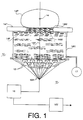
- High energy ultrasonic device 10 has a lens assembly 11 formed by an array of electrical to ultrasonic transducers 12 mounted on the convex outer surface of rigid, bowl shaped support member 13.
- the contour of the support member defines a focal depth or invivo target region 14.
- Patient 14P on an adjustable table 14T is positioned proximate to energy window 14W so that the invivo treatment site coincides with the target region.
- the space between the lens assembly and the patient contains a suitable transmission fluid 14F such as water, oil or glycerin, within rigid housing 14H.
- Flexible membrane 14M over the energy window permits fluid-to-patient interface.
- Crystal material within transducers 12 is periodically charged by a high voltage from voltage source 15V.
- the charging voltage is applied to each transducer by suitable electrical distribution leads such as conductive network 15N which is connected to one terminal of the voltage.
- support member 13 under the transducers is conductive and functions as the inner distribution conductor connected to the other terminal of the voltage.
- the applied voltage establishes an electrical field across each transducer crystal.
- the transducers are discharged rapidly by switching system 16.
- the individual pulse of ultrasonic energy from each transducer merges into a collective pulse which converges toward the target region becoming highly concentrated.
- Degassing system 17 continuously extracts gaseous material such as atmospheric air which has become dissolved or suspended in the transmission fluid.
- gaseous material such as atmospheric air which has become dissolved or suspended in the transmission fluid.
- the concentrated ultrasonic energy passing through the fluid causes gaseous material to form bubbles which diffuse or scatter the ultrasonic waves.
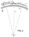
- the rear or external side of support member 13 has a convex surface machined to provide a plurality of planar mounting facets 23F.
- Each facet has a normal center line 23N perpendicular to the plane of the facet.
- the facets are orientated so that the center lines pass through a common center of curvature 14C in target region 14.
- the support member is symmetrically curved about a primary axis 13P which is preferably the normal center line through center transducer 32P (see Figure 3)
- Each transducer 12 has an inner mounting face 22M which engages one of the mounting facets 23F along a bond line 22B.
- Each transducer has a rear or outer electrode face 22E which electrically engages conductive mesh 25N by means of a suitable conductive medium such as conductive epoxy 25E.
- the high voltage terminal (HV) of the charging voltage is connected to the conductive mesh, and the ground terminal is connected to the support member.
- Transducers 12 may be disk shaped with a major dimension 22A extending generally parallel to underlying mounting facet, and a minor dimension 22a extending generally normal to the mounting facet.
- each transducer is generally planar to match the flat surface of the underlying mounting facet producing a uniform thin bond line 22B.
- Thin bonds lines establish stronger bonds with a longer service life.
- thin bond lines have less electrical resistance and will dissipate less voltage during charging and discharging of the transducers.
- a conductive bond line may function as the inner electrical distribution conductor for non-conductive support members formed of insulative materials such as plastics or ceramics.
- the internal or target side of support member 13 is a large concave surface with a plurality of smaller concave lenses or focusing surfaces 23S machined thereon.
- Each of these small focusing lens is centered in front of an opposed flat mounting facet on the other side of the support member, and is symmetrical about an axis of symmetry which passes through common point 14C.
- Each lens 23S focuses the individual pulse of energy from a single transducer at target region 14, where the individual pulses merge into an intense collective pulse.
- the diameter of the concave lenses is much less than the focal depth of the support member, which reduces edge delay within an individual pulse. That is, the path length of the energy from the edge of a transducer, through the edge of the lens, to the target region is only slightly greater than the path length of the energy from the center of the transducer, through the center of the lens. This relative size and path length relationship permits the use of true spherical sector surfaces for the focusing surface without significant compromise of the in phase condition. If preferred, the lenses may be slightly oblate to further enhance the in phase relationship within the collective pulse. The curve of the support member may also be true or oblate depending on the correction requirements.
- An independent ultrasonic unit is formed by each focusing surface, the immediately opposed mounting facet, and the transducer mounted thereover for generating an individual pulse of ultrasonic energy to be focused at the target region.
- the transducer in each unit is preferably centered on the underlying facet; and the axis of symmetry for the focusing surface in each unit is coincident with the normal center line of the opposed mounting facet.
- the contour of the support member determines the distance from the support member to the target region.
- the size of the target region and the intensity of the ultrasonic energy focused therein is determined by the machine tolerances of the mounting facets and focusing surfaces. In general, a lens assembly with smaller target region tends to erode the invivo target down to a smaller residual size.
- a target region of about 1.5-2 mm is suitable for many applications.
- the transducer centers may be arranged in a pattern of concentric hexagons of increasing size around a center position 32P which may be a transducer or an adit port for an ultrasonic imaging probe.
- the transducers are round with their centers forming the hexagons.
- the number of transducers in each hexagon increases by an increment of six.
- the first hexagon around the center position has 6 transducers, the second hexagon has 12 transducers, etc.
- Adjacent transducers within the same hexagon are separated by intra-hexagon interstitial space 32H.
- Adjacent transducers of bordering hexagons are separated by inter-hexagon interstitial space 32B.
- the lens assembly is curved, not flat: causing the interstitial spaces to decrease as the size of the hexagons increase.
- the interstitial spaces have a wedge shaped cross section as shown in Figure 2.
- the spaces are narrower along the bottom near the support member, and wider at the top near the outer contact face of the transducers.
- a suitable resilient cushioning material such as wedge shaped lattice 22L extending throughout the transducer array may be employed to prevent adjacent transducers from banging against each other during generation of the ultrasonic energy.
- the cushioning material may be an insulator for isolating the high voltage on the outer contact face of the transducer from ground on the support member. Without suitable insulation, fringe breakdown may occur around the periphery of the transducer.
- the transducers may be operated as a single array, or they may be sectored to operate as several smaller arrays as shown in the embodiment of Figure 3.
- Center array 38A has three intersecting lines of transducers formed by the transducers at the vertices of the hexagons.
- Six symmetrical side arrays 38B, 38C, 38D, 38E, 38F and 38G are formed by the transducers between the lines of subarray 38A.
- the transducers of the center array are connected together and connected to the high voltage by three strip conductors 35A.
- Each of the six side arrays has a separate mesh and connector 35B, 35C, 35D, 35E, 35F and 35G for the high voltage, and may be activated independently.
- Insulating dividers 32B, 32C, 32D, 32E, 32F and 32G extends along the interstitial space between the sectors to isolate the high voltage applied to the activated sector from the inactivated sectors.
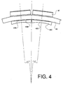
- Focusing caps 43C mounted along the inner concave surface of support member 43 may be employed to provide the focusing surface for the ultrasonic energy in place of the machined focusing surfaces 23S of the embodiment of Figure 2.
- the caps may be easily formed or machined prior to mounting within the lens assembly.
- the focusing surface may be either a true sphere or slightly oblate.
- Mounting surface 43M of the cap may be flat as shown or may be curved to facilitate bonding with the adjacent inner surface of the support member.
- the cap may be formed of any suitable material with an acoustic impedance close to the acoustic impedance of the support member.
- the material of the cap may be selected to enhance the acoustically match between the support and the transmission medium.
- the bond material within cap-to-support bond line 43B is thin to promote acoustical transfer.
- lens assembly 11 The following particulars of lens assembly 11 are given as an illustrative example of the present invention:
- Focusing Surface 23S - sector of a true sphere having curvature of about 12 ⁇ (30.5 cm) calculated from Snell's law: Rlen Rsup (1 - Vw/Va) where
- Insulative Cushion 22L - nylon wedge 100 mils (0.256 cm) across the top, 60 mils (0.154 cm across the bottom).
- the objects of this invention have been achieved by providing a lens assembly which produces less phase loss between the individual energy pulse from the transducers.
- the individual pulses arrive at the target region in a tighter group closer in time. Because of this enhanced phase condition, the lens assembly is more efficient and delivers the maximum pulse intensity with minimum operating voltage and lens area.
- the support member and focusing lenses may be simple curves having a true spherical surface to provide a simpler and less expensive lens assembly.
Landscapes
- Engineering & Computer Science (AREA)
- Physics & Mathematics (AREA)
- Acoustics & Sound (AREA)
- Multimedia (AREA)
- Mechanical Engineering (AREA)
- Surgical Instruments (AREA)
- Apparatuses For Generation Of Mechanical Vibrations (AREA)
- Ultra Sonic Daignosis Equipment (AREA)
- Transducers For Ultrasonic Waves (AREA)
Claims (33)
- Appareil à ultrasons à haute énergie (10), pour traitement in vivo, comportant:- un support rigide incurvé (13) pour définir une zone visée à traiter in vivo (14);- une série de tranducteurs électriques (12) pour produire des ultrasons, montés sur le support incurvé (13), chaque transducteur (12) ayant une dimension principale (22A) sensiblement parallèle à la partie sous-jacente du support rigide incurvé (13), et une dimension mineure (22a) sensiblement normale à la partie sous-jacente du support;- et des organes électriques de connexion (25N,HV,15N) pour relier les transducteurs (12) à une source de voltage (15V) afin d'établir à travers chaque transducteur (12) un champ électrique à convertir en énergie ultrasonore;- une surface interne concave du support incurvé (13) portant une série d'organes de focalisation (23S,43C),caractérisé en ce que le support incurvé (13) présente une surface extérieure de montage de forme convexe portant une série de facettes de montage sensiblement planes (23F), lesdits transducteurs (12) montés directement sur la surface extérieure convexe du support incurvé (13) présentant chacun une face interne de montage (22M) sensiblement plane pour se monter sur l'une des facettes de montage (23F), et chaque transducteur (12) ayant une face de contact externe (22E) adaptée à être reliée à la source de voltage (15V), le champ électrique prévu à travers chaque transducteur (12) étant établi entre la face de contact externe (22E) et la face de montage interne (22M) du transducteur, et en ce qu'un organe de focalisation (23S,43C) est prévu directement à l'opposé de chaque facette de montage (23F) ménagée sur la surface de montage externe, chaque organe de focalisation (23S,43C) formant un système unitaire à ultrasons avec la facette de montage opposée (23F) et avec le transducteur (12) monté sur celle-ci, pour focaliser l'énergie ultrasonore émise par les transducteurs.
- Appareil à ultrasons selon la revendication 1, caractérisé en ce que chaque système unitaire à ultrasons, formé par un transducteur avec sa facette de montage et son organe de focalisation, est identique aux autres systèmes unitaires à ultrasons.
- Appareil à ultrasons selon la revendication 2, caractérisé en ce que chacun des transducteurs (12) est un disque rond.
- Appareil à ultrasons selon la revendication 3, caractérisé en ce que les transducteurs en forme de disques ronds (12) sont répartis suivant un tracé en hexagones concentriques de calibre croissant.
- Appareil à ultrasons selon la revendication 4, caractérisé en ce que le tracé en hexagones concentriques augmente de calibre par tranches de six transducteurs.
- Appareil à ultrasons selon la revendication 4, caractérisé en ce que le tracé en hexagones concentriques comporte un premier hexagone qui contient 6 transducteurs, et un deuxième hexagone qui contient 12 transducteurs, puis un troisième hexagone qui contient 18 transducteurs et encore un quatrième hexagone qui contient 24 transducteurs.
- Appareil à ultrasons selon la revendication 6, caractérisé en ce que le tracé en hexagones concentriques comporte un transducteur central (32P) situé à l'intérieur du premier hexagone.
- Appareil à ultrasons selon la revendication 4, caractérisé en ce que chaque transducteur en forme de disque est séparé de chacun des transducteurs adjacents du même hexagone par un interstice (32H) dit intra-hexagone, et séparé de chaque transducteur adjacent des hexagones voisins par un interstice de bordure.
- Appareil à ultrasons selon la revendication 8, caractérisé en ce que l'interstice intra-hexagone diminue légèrement pour chaque hexagone de calibre supérieur.
- Appareil à ultrasons selon la revendication 5, caractérisé en ce qu'il comporte un moyen élastique d'amortissement (22L) disposé dans l'interstice entre deux transducteurs adjacents (12).
- Appareil à ultrasons selon la revendication 1, caractérisé en ce que le support incurvé (13) présente une courbure symétrique par rapport à un axe primaire (13P) qui passe à travers la zone visée à traiter (14) définie par le support incurvé (13).
- Appareil à ultrasons selon la revendication 11, caractérisé en ce que le support incurvé (13) est une portion de sphère parfaite au centre de laquelle se trouve la zone visée à traiter (14).
- Appareil à ultrasons selon la revendication 11, caractérisé en ce que le support incurvé (13) est une portion de sphère aplatie au centre de laquelle se trouve la zone visée à traiter (14).
- Appareil à ultrasons selon la revendication 11, caractérisé en ce que l'axe central normal (23N) de la facette de montage (23F) de chaque système unitaire à ultrasons passe par un point commun (14C) de la zone visée à traiter (14) définie par la courbure du support incurvée (13).
- Appareil à ultrasons selon la revendication 14, caractérisé en ce que l'organe de focalisation (23S,43C) de chaque système unitaire à ultrasons comporte une surface incurvée de focalisation (23S,43S) pour définir un point focal (14C) du système unitaire, situé sur l'axe central normal (23N) de ce système unitaire à ultrasons.
- Appareil à ultrasons selon la revendication 15, caractérisé en ce qu'il existe entre le rayon de courbure Rlen de la surface de focalisation (23S,43S) et le rayon de courbure Rsup du support incurvé (13) une relation telle qu'on a approximativement:
 Rlen = rayon de courbure de la surface de focalisation,Rsup = rayon de courbure du support incurvé,Vm = vitesse du son dans le milieu de transmission, etVs = vitesse du son dans la matière du support.
- Appareil à ultrasons selon la revendication 15, caractérisé en ce que la surface courbe de focalisation (23S) de chaque système unitaire à ultrasons est une surface courbe formée sur la face concave interne du support incurvé (13).
- Appareil à ultrasons selon la revendication 15, caractérisé en ce qu'il comporte en outre une série de chapeaux de focalisation (43C) montés sur la face concave interne du support incurvé (13) à proximité de la facette de montage dans chaque système unitaire à ultrasons, chaque chapeau de focalisation présentant une surface de montage interne (43M) adaptée à s'appliquer sur la face concave interne du support incurvé, et chaque chapeau comportant une surface externe de focalisation (43S) pour définir un point focal sur l'axe central du système unitaire à ultrasons correspondant.
- Appareil à ultrasons selon la revendication 15, caractérisé en ce que la courbure de la surface de focalisation (23S,43S) est celle d'une sphère parfaite.
- Appareil à ultrasons selon la revendication 15, caractérisé en ce que la courbure de la surface de focalisation (23S,43S) correspond à une sphère aplatie.
- Appareil à ultrasons selon la revendication 1, caractérisé en ce que les organes électriques de connexion comportent en outre:- une électrode externe qui traverse la face de contact externe (22E) de chaque transducteur,- une électrode interne (22B) qui traverse la face de montage interne (22M) de chaque transducteur (12),- un ensemble de conducteurs externes de distribution (15N) pour relier les électrodes externes à une borne d'une source de tension électrique (15V),- et des conducteurs de distribution internes pour relier les électrodes internes à l'autre borne de la source de tension électrique (15V).
- Appareil à ultrasons selon la revendication 21, caractérisé en ce que les électrodes externes sont constituées par un treillis conducteur (25N) qui s'étend sur les faces de contact externes (22E) des transducteurs (12) posés sur la surface de montage convexe du support incurvé (13).
- Appareil à ultrasons selon la revendication 22, caractérisé en ce qu'il comporte en outre une couche conductrice à base d'époxy (25E) pour sceller le treillis conducteur (25N) sur la face de contact externe (22E) des transducteurs (12).
- Appareil à ultrasons selon la revendication 21, caractérisé en ce que le support incurvé (13) est conducteur et constitue l'électrode interne.
- Appareil à ultrasons selon la revendication 24, caractérisé en ce que le support incurvé (13) est confectionné en aluminium.
- Appareil à ultrasons selon la revendication 24, caractérisé en ce que le support incurvé (13) est en aluminium recouvert par une couche anodisée.
- Appareil à ultrasons selon la revendication 21, caractérisé en ce que les transducteurs (12) sont scellés sur le support incurvé (13) par une couche à base d'époxy, et que le système d'électrodes internes est réalisé au moyen d'un additif conducteur prévu dans la couche à base d'époxy.
- Appareil à ultrasons selon la revendication 21, caractérisé en ce que le système des électrodes externes est relié à la borne à haute tension de la source de tension électrique (15V), le système des électrodes internes étant relié à la borne de terre de la source de tension électrique.
- Appareil à ultrasons selon la revendication 21, caractérisé en ce que l'ensemble des transducteurs est divisé en secteurs (38A-38G), deux secteurs adjacents étant séparés l'un de l'autre par l'interstice ménagé entre les transducteurs, et en ce que les conducteurs externes de distribution assurent une liaison séparée (35B-35G) entre la borne concernée de la source de tension électrique (15V) et chaque secteur de transducteurs.
- Appareil à ultrasons selon la revendication 29, caractérisé en outre en ce qu'il comporte un garnissage divisionnaire isolant (32B-32G) disposé dans l'interstice entre-transducteurs qui existe entre les secteurs adjacents de transducteurs.
- Appareil à ultrasons selon la revendication 29, caractérisé en ce que l'interstice entre-transducteurs présente une section transversale profilée en coin, la partie large de ce profil en coin étant diposée du côté de l'électrode externe, et la partie étroite du profil en coin du côté de l'électrode interne.
- Appareil à ultrasons selon la revendication 29, caractérisé en ce que les transducteurs (12) sont répartis suivant un tracé constitué d'hexagones de calibre croissant.
- Appareil à ultrasons selon la revendication 32, caractérisé en ce que les secteurs comprennent en outre un secteur central (38A) formé par les transducteurs (12) disposés à l'endroit des sommets des hexagones du tracé de répartition, et six secteurs latéraux (38B-38G) contenant les transducteurs (12) situés entre les sommets.
Applications Claiming Priority (3)
| Application Number | Priority Date | Filing Date | Title |
|---|---|---|---|
| US476874 | 1990-02-08 | ||
| US07/476,874 US5050588A (en) | 1990-02-08 | 1990-02-08 | High energy ultrasonic lens assembly with mounting facets |
| PCT/US1991/000817 WO1991011960A1 (fr) | 1990-02-08 | 1991-02-06 | Lentille ultrasonique de haute energie a facettes de montage |
Publications (3)
| Publication Number | Publication Date |
|---|---|
| EP0466910A1 EP0466910A1 (fr) | 1992-01-22 |
| EP0466910A4 EP0466910A4 (en) | 1992-09-02 |
| EP0466910B1 true EP0466910B1 (fr) | 1995-08-30 |
Family
ID=23893610
Family Applications (1)
| Application Number | Title | Priority Date | Filing Date |
|---|---|---|---|
| EP91904638A Expired - Lifetime EP0466910B1 (fr) | 1990-02-08 | 1991-02-06 | Lentille ultrasonique de haute energie a facettes de montage |
Country Status (6)
| Country | Link |
|---|---|
| US (1) | US5050588A (fr) |
| EP (1) | EP0466910B1 (fr) |
| AT (1) | ATE127263T1 (fr) |
| AU (1) | AU7306191A (fr) |
| DE (1) | DE69112527T2 (fr) |
| WO (1) | WO1991011960A1 (fr) |
Families Citing this family (33)
| Publication number | Priority date | Publication date | Assignee | Title |
|---|---|---|---|---|
| DE3803275A1 (de) * | 1988-02-04 | 1989-08-17 | Dornier Medizintechnik | Piezoelektrische stosswellenquelle |
| DE3932967A1 (de) * | 1989-10-03 | 1991-04-11 | Wolf Gmbh Richard | Ultraschall-stosswellenwandler |
| US5399158A (en) * | 1990-05-31 | 1995-03-21 | The United States Of America As Represented By The Secretary Of The Army | Method of lysing thrombi |
| US5677491A (en) * | 1994-08-08 | 1997-10-14 | Diasonics Ultrasound, Inc. | Sparse two-dimensional transducer array |
| FR2756447B1 (fr) * | 1996-11-26 | 1999-02-05 | Thomson Csf | Sonde acoustique multielements comprenant une electrode de masse commune |
| JP3331177B2 (ja) * | 1998-07-29 | 2002-10-07 | 旭光学工業株式会社 | セクタースキャン型体腔内超音波プローブ |
| US6310426B1 (en) * | 1999-07-14 | 2001-10-30 | Halliburton Energy Services, Inc. | High resolution focused ultrasonic transducer, for LWD method of making and using same |
| HU224572B1 (hu) | 2002-11-05 | 2005-11-28 | Khaled Awad Saleh Nashwan | Készülék érrendszeri megbetegedésben szenvedők infra-, hallható- és ultrahang hullámok kombinációjával való kezelésére |
| US8473239B2 (en) * | 2009-04-14 | 2013-06-25 | Maui Imaging, Inc. | Multiple aperture ultrasound array alignment fixture |
| WO2007092054A2 (fr) | 2006-02-06 | 2007-08-16 | Specht Donald F | procEDE et appareil permettant de visualiser les artEres coronaires A l'aide d'ultrasons |
| US20100262013A1 (en) * | 2009-04-14 | 2010-10-14 | Smith David M | Universal Multiple Aperture Medical Ultrasound Probe |
| EP2088932B1 (fr) | 2006-10-25 | 2020-04-08 | Maui Imaging, Inc. | Procédé et appareil de production d'images ultrasonores au moyen d'une pluralité d'orifices |
| US9282945B2 (en) | 2009-04-14 | 2016-03-15 | Maui Imaging, Inc. | Calibration of ultrasound probes |
| JP5666446B2 (ja) | 2008-08-08 | 2015-02-12 | マウイ イマギング,インコーポレーテッド | マルチアパーチャ方式の医用超音波技術を用いた画像形成方法及びアドオンシステムの同期方法 |
| WO2011103303A2 (fr) | 2010-02-18 | 2011-08-25 | Maui Imaging, Inc. | Transmission à source ponctuelle et correction de la vitesse du son à l'aide d'une imagerie par ultrasons à ouvertures multiples |
| EP2627257B1 (fr) | 2010-10-13 | 2019-04-17 | Maui Imaging, Inc. | Transducteurs à ultrasons concaves et réseaux 3d |
| WO2012051305A2 (fr) | 2010-10-13 | 2012-04-19 | Mau Imaging, Inc. | Appareil interne de sonde à ouvertures multiples et systèmes de câbles |
| CN104105449B (zh) | 2011-12-01 | 2018-07-17 | 毛伊图像公司 | 使用基于声脉冲和多孔多普勒超声的运动检测 |
| US9265484B2 (en) | 2011-12-29 | 2016-02-23 | Maui Imaging, Inc. | M-mode ultrasound imaging of arbitrary paths |
| CN107028623B (zh) | 2012-02-21 | 2020-09-01 | 毛伊图像公司 | 使用多孔超声确定材料刚度 |
| WO2013148673A1 (fr) | 2012-03-26 | 2013-10-03 | Maui Imaging, Inc. | Systèmes et procédés pour l'amélioration de la qualité d'images ultrasonores par l'application de facteurs de pondération |
| WO2014026185A1 (fr) | 2012-08-10 | 2014-02-13 | Maui Imaging, Inc. | Étalonnage de sondes à ultrasons à ouvertures multiples |
| KR102176319B1 (ko) | 2012-08-21 | 2020-11-09 | 마우이 이미징, 인코포레이티드 | 초음파 이미징 시스템 메모리 아키텍처 |
| US20140064513A1 (en) | 2012-09-06 | 2014-03-06 | MUSIC Group IP Ltd. | System and method for remotely controlling audio equipment |
| US9510806B2 (en) | 2013-03-13 | 2016-12-06 | Maui Imaging, Inc. | Alignment of ultrasound transducer arrays and multiple aperture probe assembly |
| US9883848B2 (en) | 2013-09-13 | 2018-02-06 | Maui Imaging, Inc. | Ultrasound imaging using apparent point-source transmit transducer |
| JP6722656B2 (ja) | 2014-08-18 | 2020-07-15 | マウイ イマギング,インコーポレーテッド | ネットワークベース超音波イメージングシステム |
| EP3277187B1 (fr) | 2015-03-30 | 2022-05-04 | Maui Imaging, Inc. | Procédés d'imagerie par ultrasons de détection du mouvement d'un objet |
| US10856846B2 (en) | 2016-01-27 | 2020-12-08 | Maui Imaging, Inc. | Ultrasound imaging with sparse array probes |
| AT521789B1 (de) * | 2019-05-16 | 2020-07-15 | Felix Trampler Dr | Vorrichtung zur erzeugung eines stehenden ultraschallfeldes |
| JP7724853B2 (ja) | 2020-10-21 | 2025-08-18 | マウイ イマギング,インコーポレーテッド | 多数開口超音波を用いた組織の特徴付けのためのシステム及び方法 |
| EP4236811A4 (fr) | 2020-11-02 | 2024-10-09 | Maui Imaging, Inc. | Systèmes et procédés d'amélioration de la qualité d'image ultrasonore |
| US12377017B2 (en) | 2021-10-27 | 2025-08-05 | Curative Sound, LLC | Handheld focused extracorporeal shock wave therapy device, kit, and method |
Family Cites Families (8)
| Publication number | Priority date | Publication date | Assignee | Title |
|---|---|---|---|---|
| US3587567A (en) * | 1968-12-20 | 1971-06-28 | Peter Paul Schiff | Mechanical ventricular assistance assembly |
| US3587561A (en) * | 1969-06-05 | 1971-06-28 | Hoffmann La Roche | Ultrasonic transducer assembly for biological monitoring |
| DE3319871A1 (de) * | 1983-06-01 | 1984-12-06 | Richard Wolf Gmbh, 7134 Knittlingen | Piezoelektrischer wandler zur zerstoerung von konkrementen im koerperinnern |
| US4562900A (en) * | 1984-12-20 | 1986-01-07 | Varian Associates, Inc. | Lens system for acoustic transducer array |
| US4865042A (en) * | 1985-08-16 | 1989-09-12 | Hitachi, Ltd. | Ultrasonic irradiation system |
| JPS6346147A (ja) * | 1986-04-24 | 1988-02-27 | 株式会社東芝 | 超音波治療装置 |
| EP0310380B2 (fr) * | 1987-09-30 | 1997-04-02 | Kabushiki Kaisha Toshiba | Appareil de traitement médical par ultra-son |
| US4955366A (en) * | 1987-11-27 | 1990-09-11 | Olympus Optical Co., Ltd. | Ultrasonic therapeutical apparatus |
-
1990
- 1990-02-08 US US07/476,874 patent/US5050588A/en not_active Expired - Fee Related
-
1991
- 1991-02-06 AU AU73061/91A patent/AU7306191A/en not_active Abandoned
- 1991-02-06 DE DE69112527T patent/DE69112527T2/de not_active Expired - Fee Related
- 1991-02-06 AT AT91904638T patent/ATE127263T1/de not_active IP Right Cessation
- 1991-02-06 EP EP91904638A patent/EP0466910B1/fr not_active Expired - Lifetime
- 1991-02-06 WO PCT/US1991/000817 patent/WO1991011960A1/fr not_active Ceased
Also Published As
| Publication number | Publication date |
|---|---|
| AU7306191A (en) | 1991-09-03 |
| US5050588A (en) | 1991-09-24 |
| EP0466910A4 (en) | 1992-09-02 |
| EP0466910A1 (fr) | 1992-01-22 |
| WO1991011960A1 (fr) | 1991-08-22 |
| DE69112527D1 (de) | 1995-10-05 |
| ATE127263T1 (de) | 1995-09-15 |
| DE69112527T2 (de) | 1996-05-02 |
Similar Documents
| Publication | Publication Date | Title |
|---|---|---|
| US5050588A (en) | High energy ultrasonic lens assembly with mounting facets | |
| US6104126A (en) | Composite transducer with connective backing block | |
| EP0468506B1 (fr) | Transducteur ultrasonore à biplan et origine fixe | |
| EP0310380B2 (fr) | Appareil de traitement médical par ultra-son | |
| US4640291A (en) | Bi-plane phased array for ultrasound medical imaging | |
| GB2232321A (en) | Focusing piezoelectric transducer | |
| US5706820A (en) | Ultrasonic transducer with reduced elevation sidelobes and method for the manufacture thereof | |
| EP0142215A2 (fr) | Transducteur ultrasonore ayant des modes vibratoires améliorées | |
| EP0212737B1 (fr) | Dispositif d'imagerie ultrasonore | |
| WO1996039938A1 (fr) | Transducteur constitue d'elements a dephasage et procede pour sa fabrication | |
| US5101133A (en) | Ultrasonic transducer having piezoelectric transducer elements | |
| JP2016072862A (ja) | 超音波センサー並びにプローブおよび電子機器 | |
| US5250869A (en) | Ultrasonic transducer | |
| US20220008754A1 (en) | Ultrasound emission device and ultrasound apparatus | |
| JPS6052823B2 (ja) | 超音波診断装置用プロ−ブ | |
| KR20200132475A (ko) | 마스크 및 이를 포함하는 피부 관리 기기 | |
| US11938514B2 (en) | Curved shape piezoelectric transducer and method for manufacturing the same | |
| JPH0871078A (ja) | 超音波発生装置 | |
| JPS59202059A (ja) | 超音波断層装置用探触子 | |
| JP3354195B2 (ja) | 超音波プローブ装置 | |
| JPH0538335A (ja) | 超音波探触子およびその製造方法 | |
| JPH06154233A (ja) | 衝撃波発生器 | |
| JPH04111599A (ja) | 超音波探触子 | |
| JPH01259699A (ja) | 超音波変換器 | |
| JPS6290141A (ja) | 超音波診断装置用プロ−ブ |
Legal Events
| Date | Code | Title | Description |
|---|---|---|---|
| PUAI | Public reference made under article 153(3) epc to a published international application that has entered the european phase |
Free format text: ORIGINAL CODE: 0009012 |
|
| AK | Designated contracting states |
Kind code of ref document: A1 Designated state(s): AT BE CH DE DK FR GB IT LI NL |
|
| 17P | Request for examination filed |
Effective date: 19920129 |
|
| A4 | Supplementary search report drawn up and despatched |
Effective date: 19920713 |
|
| AK | Designated contracting states |
Kind code of ref document: A4 Designated state(s): AT BE CH DE DK FR GB IT LI NL |
|
| 17Q | First examination report despatched |
Effective date: 19930909 |
|
| GRAA | (expected) grant |
Free format text: ORIGINAL CODE: 0009210 |
|
| AK | Designated contracting states |
Kind code of ref document: B1 Designated state(s): AT BE CH DE DK FR GB IT LI NL |
|
| PG25 | Lapsed in a contracting state [announced via postgrant information from national office to epo] |
Ref country code: IT Free format text: LAPSE BECAUSE OF FAILURE TO SUBMIT A TRANSLATION OF THE DESCRIPTION OR TO PAY THE FEE WITHIN THE PRE;WARNING: LAPSES OF ITALIAN PATENTS WITH EFFECTIVE DATE BEFORE 2007 MAY HAVE OCCURRED AT ANY TIME BEFORE 2007. THE CORRECT EFFECTIVE DATE MAY BE DIFFERENT FROM THE ONE RECORDED.SCRIBED TIME-LIMIT Effective date: 19950830 Ref country code: BE Effective date: 19950830 Ref country code: DK Effective date: 19950830 Ref country code: AT Effective date: 19950830 Ref country code: NL Free format text: LAPSE BECAUSE OF FAILURE TO SUBMIT A TRANSLATION OF THE DESCRIPTION OR TO PAY THE FEE WITHIN THE PRESCRIBED TIME-LIMIT Effective date: 19950830 |
|
| REF | Corresponds to: |
Ref document number: 127263 Country of ref document: AT Date of ref document: 19950915 Kind code of ref document: T |
|
| REF | Corresponds to: |
Ref document number: 69112527 Country of ref document: DE Date of ref document: 19951005 |
|
| ET | Fr: translation filed | ||
| NLV1 | Nl: lapsed or annulled due to failure to fulfill the requirements of art. 29p and 29m of the patents act | ||
| PLBE | No opposition filed within time limit |
Free format text: ORIGINAL CODE: 0009261 |
|
| STAA | Information on the status of an ep patent application or granted ep patent |
Free format text: STATUS: NO OPPOSITION FILED WITHIN TIME LIMIT |
|
| 26N | No opposition filed | ||
| PGFP | Annual fee paid to national office [announced via postgrant information from national office to epo] |
Ref country code: GB Payment date: 20000128 Year of fee payment: 10 |
|
| PGFP | Annual fee paid to national office [announced via postgrant information from national office to epo] |
Ref country code: FR Payment date: 20000224 Year of fee payment: 10 |
|
| PGFP | Annual fee paid to national office [announced via postgrant information from national office to epo] |
Ref country code: CH Payment date: 20000228 Year of fee payment: 10 |
|
| PGFP | Annual fee paid to national office [announced via postgrant information from national office to epo] |
Ref country code: DE Payment date: 20000420 Year of fee payment: 10 |
|
| PG25 | Lapsed in a contracting state [announced via postgrant information from national office to epo] |
Ref country code: GB Free format text: LAPSE BECAUSE OF NON-PAYMENT OF DUE FEES Effective date: 20010206 |
|
| PG25 | Lapsed in a contracting state [announced via postgrant information from national office to epo] |
Ref country code: CH Free format text: LAPSE BECAUSE OF NON-PAYMENT OF DUE FEES Effective date: 20010228 Ref country code: LI Free format text: LAPSE BECAUSE OF NON-PAYMENT OF DUE FEES Effective date: 20010228 |
|
| GBPC | Gb: european patent ceased through non-payment of renewal fee |
Effective date: 20010206 |
|
| REG | Reference to a national code |
Ref country code: CH Ref legal event code: PL |
|
| PG25 | Lapsed in a contracting state [announced via postgrant information from national office to epo] |
Ref country code: FR Free format text: LAPSE BECAUSE OF NON-PAYMENT OF DUE FEES Effective date: 20011031 |
|
| REG | Reference to a national code |
Ref country code: FR Ref legal event code: ST |
|
| PG25 | Lapsed in a contracting state [announced via postgrant information from national office to epo] |
Ref country code: DE Free format text: LAPSE BECAUSE OF NON-PAYMENT OF DUE FEES Effective date: 20011201 |