EP0467094A2 - Méthode et dispositif de surveillance pour transmettre des informations au moyen d'une technique de mode de transfert asynchrone en RNIS à large bande - Google Patents
Méthode et dispositif de surveillance pour transmettre des informations au moyen d'une technique de mode de transfert asynchrone en RNIS à large bande Download PDFInfo
- Publication number
- EP0467094A2 EP0467094A2 EP91110257A EP91110257A EP0467094A2 EP 0467094 A2 EP0467094 A2 EP 0467094A2 EP 91110257 A EP91110257 A EP 91110257A EP 91110257 A EP91110257 A EP 91110257A EP 0467094 A2 EP0467094 A2 EP 0467094A2
- Authority
- EP
- European Patent Office
- Prior art keywords
- information
- cells
- transmitted
- variation
- monitoring
- Prior art date
- Legal status (The legal status is an assumption and is not a legal conclusion. Google has not performed a legal analysis and makes no representation as to the accuracy of the status listed.)
- Granted
Links
Images


Classifications
-
- G—PHYSICS
- G08—SIGNALLING
- G08B—SIGNALLING SYSTEMS, e.g. PERSONAL CALLING SYSTEMS; ORDER TELEGRAPHS; ALARM SYSTEMS
- G08B13/00—Burglar, theft or intruder alarms
- G08B13/18—Actuation by interference with heat, light, or radiation of shorter wavelength; Actuation by intruding sources of heat, light, or radiation of shorter wavelength
- G08B13/189—Actuation by interference with heat, light, or radiation of shorter wavelength; Actuation by intruding sources of heat, light, or radiation of shorter wavelength using passive radiation detection systems
- G08B13/194—Actuation by interference with heat, light, or radiation of shorter wavelength; Actuation by intruding sources of heat, light, or radiation of shorter wavelength using passive radiation detection systems using image scanning and comparing systems
- G08B13/196—Actuation by interference with heat, light, or radiation of shorter wavelength; Actuation by intruding sources of heat, light, or radiation of shorter wavelength using passive radiation detection systems using image scanning and comparing systems using television cameras
- G08B13/19654—Details concerning communication with a camera
- G08B13/19658—Telephone systems used to communicate with a camera, e.g. PSTN, GSM, POTS
-
- G—PHYSICS
- G08—SIGNALLING
- G08B—SIGNALLING SYSTEMS, e.g. PERSONAL CALLING SYSTEMS; ORDER TELEGRAPHS; ALARM SYSTEMS
- G08B13/00—Burglar, theft or intruder alarms
- G08B13/18—Actuation by interference with heat, light, or radiation of shorter wavelength; Actuation by intruding sources of heat, light, or radiation of shorter wavelength
- G08B13/189—Actuation by interference with heat, light, or radiation of shorter wavelength; Actuation by intruding sources of heat, light, or radiation of shorter wavelength using passive radiation detection systems
- G08B13/194—Actuation by interference with heat, light, or radiation of shorter wavelength; Actuation by intruding sources of heat, light, or radiation of shorter wavelength using passive radiation detection systems using image scanning and comparing systems
- G08B13/196—Actuation by interference with heat, light, or radiation of shorter wavelength; Actuation by intruding sources of heat, light, or radiation of shorter wavelength using passive radiation detection systems using image scanning and comparing systems using television cameras
- G08B13/19678—User interface
- G08B13/19691—Signalling events for better perception by user, e.g. indicating alarms by making display brighter, adding text, creating a sound
-
- G—PHYSICS
- G08—SIGNALLING
- G08B—SIGNALLING SYSTEMS, e.g. PERSONAL CALLING SYSTEMS; ORDER TELEGRAPHS; ALARM SYSTEMS
- G08B13/00—Burglar, theft or intruder alarms
- G08B13/18—Actuation by interference with heat, light, or radiation of shorter wavelength; Actuation by intruding sources of heat, light, or radiation of shorter wavelength
- G08B13/189—Actuation by interference with heat, light, or radiation of shorter wavelength; Actuation by intruding sources of heat, light, or radiation of shorter wavelength using passive radiation detection systems
- G08B13/194—Actuation by interference with heat, light, or radiation of shorter wavelength; Actuation by intruding sources of heat, light, or radiation of shorter wavelength using passive radiation detection systems using image scanning and comparing systems
- G08B13/196—Actuation by interference with heat, light, or radiation of shorter wavelength; Actuation by intruding sources of heat, light, or radiation of shorter wavelength using passive radiation detection systems using image scanning and comparing systems using television cameras
- G08B13/19695—Arrangements wherein non-video detectors start video recording or forwarding but do not generate an alarm themselves
-
- G—PHYSICS
- G08—SIGNALLING
- G08B—SIGNALLING SYSTEMS, e.g. PERSONAL CALLING SYSTEMS; ORDER TELEGRAPHS; ALARM SYSTEMS
- G08B25/00—Alarm systems in which the location of the alarm condition is signalled to a central station, e.g. fire or police telegraphic systems
- G08B25/01—Alarm systems in which the location of the alarm condition is signalled to a central station, e.g. fire or police telegraphic systems characterised by the transmission medium
- G08B25/08—Alarm systems in which the location of the alarm condition is signalled to a central station, e.g. fire or police telegraphic systems characterised by the transmission medium using communication transmission lines
-
- G—PHYSICS
- G08—SIGNALLING
- G08B—SIGNALLING SYSTEMS, e.g. PERSONAL CALLING SYSTEMS; ORDER TELEGRAPHS; ALARM SYSTEMS
- G08B29/00—Checking or monitoring of signalling or alarm systems; Prevention or correction of operating errors, e.g. preventing unauthorised operation
- G08B29/02—Monitoring continuously signalling or alarm systems
-
- H—ELECTRICITY
- H04—ELECTRIC COMMUNICATION TECHNIQUE
- H04Q—SELECTING
- H04Q2213/00—Indexing scheme relating to selecting arrangements in general and for multiplex systems
- H04Q2213/13092—Scanning of subscriber lines, monitoring
-
- H—ELECTRICITY
- H04—ELECTRIC COMMUNICATION TECHNIQUE
- H04Q—SELECTING
- H04Q2213/00—Indexing scheme relating to selecting arrangements in general and for multiplex systems
- H04Q2213/13209—ISDN
-
- H—ELECTRICITY
- H04—ELECTRIC COMMUNICATION TECHNIQUE
- H04Q—SELECTING
- H04Q2213/00—Indexing scheme relating to selecting arrangements in general and for multiplex systems
- H04Q2213/1329—Asynchronous transfer mode, ATM
-
- H—ELECTRICITY
- H04—ELECTRIC COMMUNICATION TECHNIQUE
- H04Q—SELECTING
- H04Q2213/00—Indexing scheme relating to selecting arrangements in general and for multiplex systems
- H04Q2213/13337—Picturephone, videotelephony
Definitions
- the present invention relates to a telemetry monitoring method and a device therefor for transmitting information by means of asynchronous transfer mode technique in a broadband integrated services digital network (B-ISDN).
- B-ISDN broadband integrated services digital network
- B-ISDN broadband integrated services digital network
- a conventional telemetric monitoring apparatus includes a means for transmitting data of a picture, a sound or the like of a monitoring object by utilizing a communication circuit; a means for receiving the transmitted data by a monitoring device disposed at a distance; and a means for determining a normal or an abnormal state, through monitored pictures of the monitoring device, by a supervisor.
- Data of the picture or the sound of the monitoring object are collected by a television camera or a microphone.
- various kinds of sensors may be arranged at separate parts of the monitoring object, and the outputs of these sensors delivered via a communication line.
- a telemetry monitoring system through which a supervisor observes a monitoring picture, to thereby discriminate a normal state or an abnormal state, is manually operated and it is difficult to automate such a system. Accordingly, the costs of such a system are high, and often produces delays or a non-detection of an emergency.
- alarm information is output from each sensor, i.e., an alarm is output when a sensor output becomes higher than a predetermined level when an emergency or accident occurs.
- ISDN Integrated Services Digital Network
- B-ISDN broadband ISDN
- ATM asynchromous transfer mode
- a frams is constituted by a definite number of time slots and since one channel is used to utilize a particular time slot in a frame periodically, it is disadvantageous that information transmission speed is fixed to a definite value.
- the ATM technique is intended to eliminate such drawbacks.
- transfer information is divided into a fixed length of slot blocks to transfer and process.
- the fixed length of blocks for a unit of information is called a cell.
- the cell is divided into two kinds of parts; one is a region for storing transfer information per se and the other is a region in which information concerning a control for transferring cells is stored.
- the latter is regarded as a header which has a fixed length of a predetermined format and is added before an information field.
- Multiplex communication per cell unit is carried out in an ATM device.
- Information within a header is employed in order to discriminate an address of cells which is multiplexed on a transmission line. Based on the existence of transfer information to some address, cells are delivered asynchronously. If information to be transferred is vacant, a vacant cell having no information in the information field is delivered. Therefore, a fixed length of cells are flowing continuously including the case of no information to be transferred. An observation of a header in a cell enables discriminating whether a cell is vacant or not and whether or not it is a cell including information of a logic channel in response any address.
- a header includes address to multiplex or exchange thereby.
- a packet is of a variable length, and packet exchange is processed by a software, whereas since an ATM device is of a definite length, a cell appears periodically and the detection and exchange of cells are realized by a hardware to effect a high speed processing.
- a conventional circuit switching network has disadvantages that once a speed is determined it cannot be changed dynamically and must be a multiply of 64 K bit/sec, whereas if the number of cells delivered in ATM system is regulated to change a communication speed, the communication speed can be selected freely to set it dynamically.
- the present invention has been devised as a way of eliminating such problems.
- an object of the present invention is to enable a telemetry monitoring system to be automated, and to thereby reduce the labor required, and to detect an emergency or accident of an earliest stage.
- a telemetry supervisory system in an asynchronous transmission mode network which discriminates less information when less variation rate occur and more information when more variation rates occur, and provides a transmission system for transmitting the discriminated information as a cell having a fixed length, wherein monitoring information such as a picture image or sound from a monitored object is transmitted for a discrimination of the information, a number of cells transmitted as data is monitored at the receiving side, and a variation of the number of cells is treated as a change in the state of the monitored object.
- the number of cells received is monitored and a normal state or an abnormal state detected based on a change of the number of calls per unit of time.
- the number of cells is counted at the receiving side, and an alarm data signal is produced according to the counted number. For example, when the counted number is more than a predetermined number, a pilot lamp is turned ON, a buzzer alarm is sounded, or a picture image is displayed on a monitoring screen.
- a precise alarm signal can be transmitted.
- the information to be transmitted is, for example, a temperature of the monitored object
- a value of the temperature per se is transmitted as cell data, and a change thereof as is recorded as a variation of a number of the transmitted cells.
- the cell data and the variation of a number of transmitted cells are received, and when the variation of a number of transmitted cells is more then a predetermined value, a pilot lamp is turned ON, a buzzer alarm is sounded, and the current temperature thereof is indicated at a display unit.
- the information to be transmitted is a picture image of the monitored object
- a difference between a prior picture image and a current picture image is transmitted as cell data, and the difference therebetween (variation speed) is transmitted as a variation of the number of cells.
- This information is received at the receiving side, and when the variation of the number of transmitted cells is more than a predetermined value, a buzzer alarm is sounded and the picture image is shown on the screen of the display unit. Therefore, the supervisor need only listen for the sound for the buzzer, look at the display, and visually check whether or not the monitored object is in a normal state.
- reference numeral 10 denotes a monitored object, for example, an office which is to be monitored, more particularly, a space within the office, and 12 denoted a television camera mounted within the office.
- the output of the TV camera is encoded by a variable rate CODEC device (VRC) 14, and then output by an asynchronous transmission mode device (ATM) 16 and delivered to a monitoring station 20, in this case to a security company, via a communication network 18.
- VRC variable rate CODEC device
- ATM asynchronous transmission mode device
- the delivered signal is decoded by a variable rate CODEC device (VRC) 22 at a monitoring station 20, and the output thereof input to a display unit (a monitoring CRT) 24.
- VRC variable rate CODEC device
- transmitted data of a number of cells per unit of time is counted by a counter 26, and the difference between a prior number of cells and a current number of cells per unit time is detected by a detection unit 28.
- An alarm portion 30 receives an output of the detection unit 28, and when the value of the detected difference is more than a predetermined value, the VRC 22 is informed of an abnormality by an abnormality informing portion 30, and is activated thereby, and accordingly, a picture image of the monitored object 10 is then displayed on a monitoring screen 24.
- VRC variable rate CODEC
- B-ISDN broadband integrated services digital network
- the office In a normal case, the office is not manned at night and a picture image taken by a crime prevention camera 12 does not change, and therefore, the number of cells delivered is low. In an emergency case, however, e.g., if an intruder enters the office, a change occurs in a picture image and the difference between a prior image and the current image is transmitted, and thus the number of transmitted cells is increased.
- the counter 26 counts the cells and the detection unit 28 detects the rate of increase the reofand when the amount of increase is more than a predetermined value, the alarm informing portion 30 outputs an alarm signal.
- a picture image is shown on the monitoring screen 24, and a supervisor then observes the screen and is able to discriminate a normal state from an abnormal state.
- the supervisory station is generally a central supervisory station to which picture images are sent of many monitored objects, and these pictures are shown on respective monitoring screens. Therefore, it is not easy to closely observe so many picture images displayed on a multitude of monitor screens, and thus it is difficult to rapidly determine a variation (abnormal state) shown on one of the many monitor screens.
- an abnormal state is produced at a level higher than a predetermined value
- the picture image concerned is shown on the relevant monitoring screen; until that time, the monitoring screen does not display a picture image.
- both methods i.e., turning ON a pilot lamp and sounding a buzzer, may be used.
- a supervisor can manually display a required picture image of monitored object on the monitoring screen.
- the above-noted predetermined value for outputting an alarm may be made variable, to cause a display even when a minute variation occurs or to stop a display unit unless a large variation occurs.
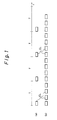
- Fig. 3 is a diagram showing an embodiment when the invention is utilized in the case of a fire alarm.
- a monitoring object 10 for example, the temperature of a room at usual home is monitored by a sensor 32 and it is devised that the greater the rise of a room temperature per unit time is, the more the number of transmitted cells in creases.
- the delivery of information (The value of temperature or the difference of the temperature is preferable, but we may make do with a simple sign or code) is thinned out and a circuit design is devised such that the larger the difference is, the more the delivery frequency is increased.
- the number of received cells is counted at a monitoring station (at the receiving side) 20 and if the number of cells denotes an increase over a predetermined value, an alarm is produced from a speaker 34.
- information included in a cell or information within a cell is a non-objective one which is not useful or meaningless and the number of cells corresponds to an alarm signal, but information within a cell may be selected as a value of temperature, an indoor sound, a smoke information or the like may be selected. Such being the case, these monitored information may be broadcasted from a speaker.
- Fig. 4 is a block diagram showing another embodiment of the invention having a plurality of monitoring objects.
- a monitoring object 10 includes a television camera 12, a set of sensors 32 and a mocrophone 36, where a set of sensors 32 further include a sensor for measuring temperature, a sensor for checking whether the door is locked by a key or not, and a sensor for checking whether the window is closed or open.
- the sensor enables effecting a valid monitoring against a fire or an intruder.
- the number of transmitted cells is also responsive to a variation rate and the information of a picture image, a sound, a temperature and so on, is packaged in the cell.
- the number of monitoring object is not limited to only one, but a plurality of monitoring objects may be employed with a switching means contained in either monitoring object. In this case, whenever an alarm signal is informed, a switching to a picture image of the relevant monitoring object may be possible. If the supervisor can not find an abnormal state on a monitoring screen of a display unit, a return operation to a normal state which a picture image does not appear, may be preferred.
- Fig. 5 is a obtained is a detailed block diagram of a monitoring station 20 in Fig. 2.
- the output of the network 18 is sent to a header matching circuit 21 of a monitoring station 20.
- the output in a header matching circuit 21 sends each header coincidence signal of the circuit 21 to a respective cell number counter 261 to 263.
- each input of the cell number counters 261 to 263 is sent to a respective cell disassembly circuit 211 to 213.
- Each picture signal as the output of the VRC decoder 221 to 223 is sent to a selector 23 to select a desired picture and then is sent to a display unit 24.
- each data from the header matching circuit 21 is sent to the cell disassembly circuit 211 to 213.
- the outputs of the cell number counters 261 to 263 is sent to the count number monitor 28 where the increase of the count value is detected.
- the output of the count number monitor 28 is sent to the selector 23.
- the count values of the cell number counter 261 to 263 are read and when the count value surpasses a threshold value, a picture image signal is selected.
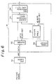
- Fig. 6 is a schematic block diagram showing a cell assembly circuit 16 in Fig. 2.
- a picture signal is sent to a VRC coder 51 and the output of the VRC coder 51 is input to a buffer 52 to store VRC data therein.
- One of the signals produced from a timing circuit 56 is sent to a buffer 52 and the other of them is sent to a VCI/VPI Hold circuit 55 to receive a header read-out signal from the timing circuit 56.
- the output of hold circuit 55 and the output of the buffer 52 are multiplexed in a header provision circuit 53 and the multiplexed signal is sent to a cyclic redundancy check code circuit 54 to add a header error control signal.
- a VCI signal in 55 is a virtual channel identifier signal which identifies a channel is a network.
- a VPI signal in 55 is a virtual pass identifier signal which identifies a password in a network.
- a combination of VCI and VPI carries out a response to an address to which a cell is to be transmitted.
- a CRC denotes a cyclic redundancy check code which an input signal is divided by a generation polynomial and a residue thereof is added by means of the CRC code.
- a HEC denotes a header error control and the CRC is counted in response to four bytes of a header and put in a field of this header. A detection/correction of bit errors in a header can be carried out thereby.
- each information sent from the buffer 52 and each VCI/VPI data sent from the VCI/VPI hold circuit 55 are paired therewith, i.e., VRC coded data is multiplexed with VCI/VPI data and HEC (header error control) data is added to the multiplexed data in the HEC provision circuit 54 to be sent to a network 18.
- VRC coded data is multiplexed with VCI/VPI data
- HEC (header error control) data is added to the multiplexed data in the HEC provision circuit 54 to be sent to a network 18.
- header data which is obtained by destination VCI/VPI data is added to the image information to be sent to the network.
Landscapes
- Physics & Mathematics (AREA)
- General Physics & Mathematics (AREA)
- Engineering & Computer Science (AREA)
- Computer Security & Cryptography (AREA)
- Human Computer Interaction (AREA)
- Multimedia (AREA)
- Business, Economics & Management (AREA)
- Emergency Management (AREA)
- Data Exchanges In Wide-Area Networks (AREA)
- Alarm Systems (AREA)
- Selective Calling Equipment (AREA)
- Closed-Circuit Television Systems (AREA)
Applications Claiming Priority (2)
| Application Number | Priority Date | Filing Date | Title |
|---|---|---|---|
| JP2163633A JP2828324B2 (ja) | 1990-06-21 | 1990-06-21 | 遠隔監視システム |
| JP163633/90 | 1990-06-21 |
Publications (3)
| Publication Number | Publication Date |
|---|---|
| EP0467094A2 true EP0467094A2 (fr) | 1992-01-22 |
| EP0467094A3 EP0467094A3 (en) | 1992-07-01 |
| EP0467094B1 EP0467094B1 (fr) | 1998-03-04 |
Family
ID=15777645
Family Applications (1)
| Application Number | Title | Priority Date | Filing Date |
|---|---|---|---|
| EP91110257A Expired - Lifetime EP0467094B1 (fr) | 1990-06-21 | 1991-06-21 | Système de surveillance par télémétrie |
Country Status (5)
| Country | Link |
|---|---|
| US (1) | US5270811A (fr) |
| EP (1) | EP0467094B1 (fr) |
| JP (1) | JP2828324B2 (fr) |
| CA (1) | CA2045055C (fr) |
| DE (1) | DE69128988T2 (fr) |
Cited By (11)
| Publication number | Priority date | Publication date | Assignee | Title |
|---|---|---|---|---|
| EP0466492A3 (en) * | 1990-07-13 | 1993-07-28 | Kabushiki Kaisha Toshiba | Monitor system |
| EP0554948A1 (fr) * | 1992-02-06 | 1993-08-11 | Philips Patentverwaltung GmbH | Dispositif pour la télésurveillance de locaux |
| DE4407046A1 (de) * | 1994-03-03 | 1995-09-07 | Deutsche Bundespost Telekom | Verfahren und Anordnung zur Sicherung der Übertragung von Alarm- und Notrufdaten über ein ISDN-Netz |
| WO1997020293A1 (fr) * | 1995-11-30 | 1997-06-05 | David Antony Crellin | Procede et dispositif servant a generer un enregistrement visuel |
| DE19814172A1 (de) * | 1998-03-30 | 1999-10-07 | Frank Natzius | Alarmmeldeeinrichtung zur Fernüberwachung von beliebigen Objekten |
| WO1999059332A1 (fr) * | 1998-05-08 | 1999-11-18 | Baxall Security Limited | Camera video a haute resolution amelioree |
| EP1445938A1 (fr) * | 2002-11-25 | 2004-08-11 | Eastman Kodak Company | Méthode et système d'imagerie de surveillance de la santé et de la sécurite personelle |
| EP1106470B1 (fr) * | 1999-12-04 | 2006-01-11 | Alcatel | Procédé pour détecter des obstacles sur des sections de voie de chemin de fer |
| US7046924B2 (en) | 2002-11-25 | 2006-05-16 | Eastman Kodak Company | Method and computer program product for determining an area of importance in an image using eye monitoring information |
| US7206022B2 (en) | 2002-11-25 | 2007-04-17 | Eastman Kodak Company | Camera system with eye monitoring |
| US7233684B2 (en) | 2002-11-25 | 2007-06-19 | Eastman Kodak Company | Imaging method and system using affective information |
Families Citing this family (36)
| Publication number | Priority date | Publication date | Assignee | Title |
|---|---|---|---|---|
| US5550584A (en) * | 1992-02-19 | 1996-08-27 | Canopus Co., Ltd. | Bus-line network communication system |
| US5581297A (en) * | 1992-07-24 | 1996-12-03 | Intelligent Instruments Corporation | Low power video security monitoring system |
| JPH06169320A (ja) * | 1992-10-02 | 1994-06-14 | Toshiba Corp | Atmセル化装置 |
| JP3381077B2 (ja) * | 1992-12-04 | 2003-02-24 | ソニー株式会社 | 動画像復号装置 |
| US7558324B2 (en) * | 1993-01-18 | 2009-07-07 | Sony Corporation | Apparatus for encoding and decoding header data in picture signal transmission |
| US7075991B1 (en) | 1993-01-18 | 2006-07-11 | Sony Corporation | Apparatus for encoding and decoding header data in picture signal transmission |
| USRE43462E1 (en) | 1993-04-21 | 2012-06-12 | Kinya (Ken) Washino | Video monitoring and conferencing system |
| DE4329898A1 (de) | 1993-09-04 | 1995-04-06 | Marcus Dr Besson | Kabelloses medizinisches Diagnose- und Überwachungsgerät |
| EP0666542A3 (fr) * | 1994-02-04 | 1996-05-15 | Fuji Facom Corp | Système multimédia de surveillance et de commande des procédés. |
| DE4408558C1 (de) * | 1994-03-14 | 1995-03-23 | Hitschfel Werner | Alarmanlage zur Überwachung von Gebäuden, Räumen, Geländeabschnitten oder Gegenständen |
| US5521634A (en) * | 1994-06-17 | 1996-05-28 | Harris Corporation | Automatic detection and prioritized image transmission system and method |
| DE4423947A1 (de) * | 1994-07-07 | 1996-01-11 | Aeg Sensorsysteme Gmbh | Einbruchmeldeanlage |
| US5496156A (en) * | 1994-09-22 | 1996-03-05 | Tecumseh Products Company | Suction muffler |
| CA2155719C (fr) * | 1994-11-22 | 2005-11-01 | Terry Laurence Glatt | Systeme de surveillance video avec cameras pilotes et asservies |
| US5583863A (en) * | 1995-01-31 | 1996-12-10 | Bell Atlantic Network Services, Inc. | Full service network using asynchronous transfer mode multiplexing |
| WO1996031067A1 (fr) * | 1995-03-24 | 1996-10-03 | Ppt Vision, Inc. | Liaison video serie numerique a grande vitesse |
| DE19512959A1 (de) * | 1995-04-10 | 1996-10-17 | Sel Alcatel Ag | Fernüberwachungsvorrichtung |
| US5535209A (en) * | 1995-04-10 | 1996-07-09 | Digital Equipment Corporation | Method and apparatus for transporting timed program data using single transport schedule |
| US5786746A (en) * | 1995-10-03 | 1998-07-28 | Allegro Supercare Centers, Inc. | Child care communication and surveillance system |
| US5767791A (en) * | 1995-11-13 | 1998-06-16 | Vitalcom | Low-power circuit and method for providing rapid frequency lock in a wireless communications device |
| US5944659A (en) | 1995-11-13 | 1999-08-31 | Vitalcom Inc. | Architecture for TDMA medical telemetry system |
| US6314140B1 (en) * | 1995-12-28 | 2001-11-06 | Lucent Technologies Inc. | Dynamic video focus control |
| DE19624542A1 (de) * | 1996-06-20 | 1998-01-02 | Siegenia Frank Kg | Vorrichtung zur Einbruchsmeldung bzw. Zugangserfassung |
| US6031573A (en) * | 1996-10-31 | 2000-02-29 | Sensormatic Electronics Corporation | Intelligent video information management system performing multiple functions in parallel |
| US6384862B1 (en) * | 1997-03-12 | 2002-05-07 | Telefoaktiebolaget L M Ericsson | Imaging system and method for interactive control of image quality |
| US8073921B2 (en) * | 1997-07-01 | 2011-12-06 | Advanced Technology Company, LLC | Methods for remote monitoring and control of appliances over a computer network |
| US6188830B1 (en) | 1997-07-14 | 2001-02-13 | Sony Corporation | Audiovisual effects processing method and apparatus for instantaneous storage-based playback of audio data in synchronization with video data |
| US6424371B1 (en) * | 1997-09-24 | 2002-07-23 | Sheree H. Wen | Intelligent video monitor system |
| US7075918B1 (en) | 1999-12-30 | 2006-07-11 | At&T Corp. | BRG with PBX capabilities |
| US6441747B1 (en) | 2000-04-18 | 2002-08-27 | Motorola, Inc. | Wireless system protocol for telemetry monitoring |
| US6496705B1 (en) | 2000-04-18 | 2002-12-17 | Motorola Inc. | Programmable wireless electrode system for medical monitoring |
| WO2002005700A2 (fr) | 2000-07-18 | 2002-01-24 | Motorola, Inc. | Procede et systeme d'electrocardiographe sans fil |
| US7197357B2 (en) | 2001-07-17 | 2007-03-27 | Life Sync Corporation | Wireless ECG system |
| US20040127802A1 (en) * | 2001-07-17 | 2004-07-01 | Gmp Companies, Inc. | Wireless ECG system |
| US7933642B2 (en) | 2001-07-17 | 2011-04-26 | Rud Istvan | Wireless ECG system |
| US11868433B2 (en) * | 2020-11-20 | 2024-01-09 | Accenture Global Solutions Limited | Target object identification for waste processing |
Family Cites Families (11)
| Publication number | Priority date | Publication date | Assignee | Title |
|---|---|---|---|---|
| AU498573B2 (en) * | 1974-06-18 | 1979-03-15 | Aboyne Pty. Ltd. | Information transmission system |
| CA1116286A (fr) * | 1979-02-20 | 1982-01-12 | Control Data Canada, Ltd. | Systeme de surveillance anti-effraction en peripherie |
| US4317130A (en) * | 1979-10-10 | 1982-02-23 | Motorola, Inc. | Narrow band television transmission system |
| JPS60157699A (ja) * | 1984-01-27 | 1985-08-17 | ホーチキ株式会社 | 異常状態警報装置 |
| JPS6139194A (ja) * | 1984-07-31 | 1986-02-25 | ホーチキ株式会社 | 火災警報装置 |
| US4679077A (en) * | 1984-11-10 | 1987-07-07 | Matsushita Electric Works, Ltd. | Visual Image sensor system |
| EP0318039B1 (fr) * | 1987-11-26 | 1995-02-01 | Fujitsu Limited | Système de surveillance d'urgence à traitement d'image à infrarouge |
| JPH0813057B2 (ja) * | 1989-02-03 | 1996-02-07 | 日本電気株式会社 | Hdlc可変長パケットと非hdlc固定長パケットとの混在転送方法 |
| NL8900640A (nl) * | 1989-03-16 | 1990-10-16 | At & T & Philips Telecomm | Werkwijze voor het in atd (asynchronous time division) overdragen van datapakketten en een inrichting voor toepassing van deze werkwijze. |
| JP2551144B2 (ja) * | 1989-04-14 | 1996-11-06 | 日本電気株式会社 | トラフィック監視装置 |
| JP2837182B2 (ja) * | 1989-08-04 | 1998-12-14 | 富士通株式会社 | セルデータの伝送方法、送信要求処理方法及びスイッチ |
-
1990
- 1990-06-21 JP JP2163633A patent/JP2828324B2/ja not_active Expired - Lifetime
-
1991
- 1991-06-20 CA CA002045055A patent/CA2045055C/fr not_active Expired - Fee Related
- 1991-06-21 EP EP91110257A patent/EP0467094B1/fr not_active Expired - Lifetime
- 1991-06-21 US US07/718,794 patent/US5270811A/en not_active Expired - Fee Related
- 1991-06-21 DE DE69128988T patent/DE69128988T2/de not_active Expired - Fee Related
Cited By (16)
| Publication number | Priority date | Publication date | Assignee | Title |
|---|---|---|---|---|
| US5802494A (en) * | 1990-07-13 | 1998-09-01 | Kabushiki Kaisha Toshiba | Patient monitoring system |
| EP0466492A3 (en) * | 1990-07-13 | 1993-07-28 | Kabushiki Kaisha Toshiba | Monitor system |
| EP0554948A1 (fr) * | 1992-02-06 | 1993-08-11 | Philips Patentverwaltung GmbH | Dispositif pour la télésurveillance de locaux |
| DE4407046A1 (de) * | 1994-03-03 | 1995-09-07 | Deutsche Bundespost Telekom | Verfahren und Anordnung zur Sicherung der Übertragung von Alarm- und Notrufdaten über ein ISDN-Netz |
| DE4407046C2 (de) * | 1994-03-03 | 2001-05-10 | Deutsche Telekom Ag | Verfahren und Anordnung zur Sicherung der Übertragung von Alarm- und Notrufdaten über ein ISDN-Netz |
| WO1997020293A1 (fr) * | 1995-11-30 | 1997-06-05 | David Antony Crellin | Procede et dispositif servant a generer un enregistrement visuel |
| DE19814172A1 (de) * | 1998-03-30 | 1999-10-07 | Frank Natzius | Alarmmeldeeinrichtung zur Fernüberwachung von beliebigen Objekten |
| WO1999059332A1 (fr) * | 1998-05-08 | 1999-11-18 | Baxall Security Limited | Camera video a haute resolution amelioree |
| EP1106470B1 (fr) * | 1999-12-04 | 2006-01-11 | Alcatel | Procédé pour détecter des obstacles sur des sections de voie de chemin de fer |
| EP1445938A1 (fr) * | 2002-11-25 | 2004-08-11 | Eastman Kodak Company | Méthode et système d'imagerie de surveillance de la santé et de la sécurite personelle |
| US7046924B2 (en) | 2002-11-25 | 2006-05-16 | Eastman Kodak Company | Method and computer program product for determining an area of importance in an image using eye monitoring information |
| US7206022B2 (en) | 2002-11-25 | 2007-04-17 | Eastman Kodak Company | Camera system with eye monitoring |
| US7233684B2 (en) | 2002-11-25 | 2007-06-19 | Eastman Kodak Company | Imaging method and system using affective information |
| CN100352255C (zh) * | 2002-11-25 | 2007-11-28 | 伊斯曼柯达公司 | 用于健康监视和个人安全的成像方法和系统 |
| US7319780B2 (en) | 2002-11-25 | 2008-01-15 | Eastman Kodak Company | Imaging method and system for health monitoring and personal security |
| US7418116B2 (en) | 2002-11-25 | 2008-08-26 | Eastman Kodak Company | Imaging method and system |
Also Published As
| Publication number | Publication date |
|---|---|
| EP0467094A3 (en) | 1992-07-01 |
| JP2828324B2 (ja) | 1998-11-25 |
| US5270811A (en) | 1993-12-14 |
| DE69128988D1 (de) | 1998-04-09 |
| EP0467094B1 (fr) | 1998-03-04 |
| CA2045055A1 (fr) | 1991-12-22 |
| DE69128988T2 (de) | 1998-07-16 |
| JPH0454098A (ja) | 1992-02-21 |
| CA2045055C (fr) | 1998-05-12 |
Similar Documents
| Publication | Publication Date | Title |
|---|---|---|
| US5270811A (en) | Telemetry monitoring method and device therefor for transmitting information by means of asynchronous transfer mode technique in broadband ISDN | |
| CA1160311A (fr) | Systeme de signalisation d'alarmes a poste central | |
| US5659540A (en) | Apparatus and method for detection of operation administration and management (OAM) cell loopback and physical loopbacks in an asynchronous transfer mode (ATM) network | |
| US5039980A (en) | Multi-nodal communication network with coordinated responsibility for global functions by the nodes | |
| US5864555A (en) | Method and apparatus for generating a proxy connection endpoint for operation administration and management (OAM) asynchronous transfer mode (ATM) cells | |
| US5440688A (en) | Network management system employing a main processor and an auxiliary processor to receive alarm messages and transmit recovery commands | |
| US6023455A (en) | Loopback cell control system | |
| JP3302578B2 (ja) | Oam処理装置 | |
| CA2006505C (fr) | Radiomessagerie a comparaison de textes | |
| EP0817439A2 (fr) | Appareil et procédé de commutation | |
| JPH11177969A (ja) | 画像監視装置 | |
| JPH10191307A (ja) | 画像監視システム | |
| WO1998032106A1 (fr) | Systemes de securite video | |
| JP3192901B2 (ja) | 可変速度データ送信装置及び可変速度データ受信装置 | |
| JP3193192B2 (ja) | Atm伝送装置における監視装置 | |
| JPH0227887A (ja) | 画像伝送装置 | |
| US4706241A (en) | Low speed gate circuit | |
| JPH1023024A (ja) | Atm交換装置およびその方法 | |
| JPH09284751A (ja) | 監視カメラ装置 | |
| JP2801696B2 (ja) | 遠隔監視システムの端末装置 | |
| JPH1051462A (ja) | Atm通信装置における装置内監視方式 | |
| KR100242317B1 (ko) | 실시간 비데오 서비스의 상태감시 장치 및 방법 | |
| JPH04207734A (ja) | セル送受信装置 | |
| JPH07115419A (ja) | セル組立多重処理装置 | |
| JPH09231489A (ja) | 防犯警備システム及びそれに用いる端末装置 |
Legal Events
| Date | Code | Title | Description |
|---|---|---|---|
| PUAI | Public reference made under article 153(3) epc to a published international application that has entered the european phase |
Free format text: ORIGINAL CODE: 0009012 |
|
| AK | Designated contracting states |
Kind code of ref document: A2 Designated state(s): DE FR GB |
|
| PUAL | Search report despatched |
Free format text: ORIGINAL CODE: 0009013 |
|
| AK | Designated contracting states |
Kind code of ref document: A3 Designated state(s): DE FR GB |
|
| 17P | Request for examination filed |
Effective date: 19921221 |
|
| 17Q | First examination report despatched |
Effective date: 19950727 |
|
| GRAG | Despatch of communication of intention to grant |
Free format text: ORIGINAL CODE: EPIDOS AGRA |
|
| GRAG | Despatch of communication of intention to grant |
Free format text: ORIGINAL CODE: EPIDOS AGRA |
|
| GRAH | Despatch of communication of intention to grant a patent |
Free format text: ORIGINAL CODE: EPIDOS IGRA |
|
| GRAH | Despatch of communication of intention to grant a patent |
Free format text: ORIGINAL CODE: EPIDOS IGRA |
|
| GRAA | (expected) grant |
Free format text: ORIGINAL CODE: 0009210 |
|
| AK | Designated contracting states |
Kind code of ref document: B1 Designated state(s): DE FR GB |
|
| REF | Corresponds to: |
Ref document number: 69128988 Country of ref document: DE Date of ref document: 19980409 |
|
| ET | Fr: translation filed | ||
| PLBE | No opposition filed within time limit |
Free format text: ORIGINAL CODE: 0009261 |
|
| STAA | Information on the status of an ep patent application or granted ep patent |
Free format text: STATUS: NO OPPOSITION FILED WITHIN TIME LIMIT |
|
| 26N | No opposition filed | ||
| REG | Reference to a national code |
Ref country code: GB Ref legal event code: IF02 |
|
| PGFP | Annual fee paid to national office [announced via postgrant information from national office to epo] |
Ref country code: FR Payment date: 20030610 Year of fee payment: 13 |
|
| PGFP | Annual fee paid to national office [announced via postgrant information from national office to epo] |
Ref country code: GB Payment date: 20030618 Year of fee payment: 13 |
|
| PGFP | Annual fee paid to national office [announced via postgrant information from national office to epo] |
Ref country code: DE Payment date: 20030707 Year of fee payment: 13 |
|
| PG25 | Lapsed in a contracting state [announced via postgrant information from national office to epo] |
Ref country code: GB Free format text: LAPSE BECAUSE OF NON-PAYMENT OF DUE FEES Effective date: 20040621 |
|
| PG25 | Lapsed in a contracting state [announced via postgrant information from national office to epo] |
Ref country code: DE Free format text: LAPSE BECAUSE OF NON-PAYMENT OF DUE FEES Effective date: 20050101 |
|
| GBPC | Gb: european patent ceased through non-payment of renewal fee |
Effective date: 20040621 |
|
| PG25 | Lapsed in a contracting state [announced via postgrant information from national office to epo] |
Ref country code: FR Free format text: LAPSE BECAUSE OF NON-PAYMENT OF DUE FEES Effective date: 20050228 |
|
| REG | Reference to a national code |
Ref country code: FR Ref legal event code: ST |