EP0467830A1 - Cartouche à distribution multiple pour pâtes constituées par plusieurs composants - Google Patents
Cartouche à distribution multiple pour pâtes constituées par plusieurs composants Download PDFInfo
- Publication number
- EP0467830A1 EP0467830A1 EP91810512A EP91810512A EP0467830A1 EP 0467830 A1 EP0467830 A1 EP 0467830A1 EP 91810512 A EP91810512 A EP 91810512A EP 91810512 A EP91810512 A EP 91810512A EP 0467830 A1 EP0467830 A1 EP 0467830A1
- Authority
- EP
- European Patent Office
- Prior art keywords
- discharge
- insert
- closure
- channel
- cylinder
- Prior art date
- Legal status (The legal status is an assumption and is not a legal conclusion. Google has not performed a legal analysis and makes no representation as to the accuracy of the status listed.)
- Granted
Links
- 230000007704 transition Effects 0.000 claims abstract description 14
- 238000011144 upstream manufacturing Methods 0.000 claims abstract description 3
- 238000007789 sealing Methods 0.000 claims description 2
- 230000006978 adaptation Effects 0.000 abstract description 2
- 239000000463 material Substances 0.000 description 5
- 239000000243 solution Substances 0.000 description 3
- 238000009825 accumulation Methods 0.000 description 2
- 230000035508 accumulation Effects 0.000 description 2
- 238000011109 contamination Methods 0.000 description 1
- 238000009792 diffusion process Methods 0.000 description 1
- 230000000694 effects Effects 0.000 description 1
- 238000001746 injection moulding Methods 0.000 description 1
- 238000004519 manufacturing process Methods 0.000 description 1
- 238000000034 method Methods 0.000 description 1
- 239000000203 mixture Substances 0.000 description 1
- 230000000284 resting effect Effects 0.000 description 1
- 239000007921 spray Substances 0.000 description 1
Images

Classifications
-
- B—PERFORMING OPERATIONS; TRANSPORTING
- B05—SPRAYING OR ATOMISING IN GENERAL; APPLYING FLUENT MATERIALS TO SURFACES, IN GENERAL
- B05C—APPARATUS FOR APPLYING FLUENT MATERIALS TO SURFACES, IN GENERAL
- B05C17/00—Hand tools or apparatus using hand held tools, for applying liquids or other fluent materials to, for spreading applied liquids or other fluent materials on, or for partially removing applied liquids or other fluent materials from, surfaces
- B05C17/005—Hand tools or apparatus using hand held tools, for applying liquids or other fluent materials to, for spreading applied liquids or other fluent materials on, or for partially removing applied liquids or other fluent materials from, surfaces for discharging material from a reservoir or container located in or on the hand tool through an outlet orifice by pressure without using surface contacting members like pads or brushes
- B05C17/00503—Details of the outlet element
- B05C17/00506—Means for connecting the outlet element to, or for disconnecting it from, the hand tool or its container
- B05C17/00513—Means for connecting the outlet element to, or for disconnecting it from, the hand tool or its container of the thread type
-
- B—PERFORMING OPERATIONS; TRANSPORTING
- B05—SPRAYING OR ATOMISING IN GENERAL; APPLYING FLUENT MATERIALS TO SURFACES, IN GENERAL
- B05C—APPARATUS FOR APPLYING FLUENT MATERIALS TO SURFACES, IN GENERAL
- B05C17/00—Hand tools or apparatus using hand held tools, for applying liquids or other fluent materials to, for spreading applied liquids or other fluent materials on, or for partially removing applied liquids or other fluent materials from, surfaces
- B05C17/005—Hand tools or apparatus using hand held tools, for applying liquids or other fluent materials to, for spreading applied liquids or other fluent materials on, or for partially removing applied liquids or other fluent materials from, surfaces for discharging material from a reservoir or container located in or on the hand tool through an outlet orifice by pressure without using surface contacting members like pads or brushes
- B05C17/00503—Details of the outlet element
- B05C17/00516—Shape or geometry of the outlet orifice or the outlet element
-
- B—PERFORMING OPERATIONS; TRANSPORTING
- B05—SPRAYING OR ATOMISING IN GENERAL; APPLYING FLUENT MATERIALS TO SURFACES, IN GENERAL
- B05C—APPARATUS FOR APPLYING FLUENT MATERIALS TO SURFACES, IN GENERAL
- B05C17/00—Hand tools or apparatus using hand held tools, for applying liquids or other fluent materials to, for spreading applied liquids or other fluent materials on, or for partially removing applied liquids or other fluent materials from, surfaces
- B05C17/005—Hand tools or apparatus using hand held tools, for applying liquids or other fluent materials to, for spreading applied liquids or other fluent materials on, or for partially removing applied liquids or other fluent materials from, surfaces for discharging material from a reservoir or container located in or on the hand tool through an outlet orifice by pressure without using surface contacting members like pads or brushes
- B05C17/00553—Hand tools or apparatus using hand held tools, for applying liquids or other fluent materials to, for spreading applied liquids or other fluent materials on, or for partially removing applied liquids or other fluent materials from, surfaces for discharging material from a reservoir or container located in or on the hand tool through an outlet orifice by pressure without using surface contacting members like pads or brushes with means allowing the stock of material to consist of at least two different components
-
- B—PERFORMING OPERATIONS; TRANSPORTING
- B65—CONVEYING; PACKING; STORING; HANDLING THIN OR FILAMENTARY MATERIAL
- B65D—CONTAINERS FOR STORAGE OR TRANSPORT OF ARTICLES OR MATERIALS, e.g. BAGS, BARRELS, BOTTLES, BOXES, CANS, CARTONS, CRATES, DRUMS, JARS, TANKS, HOPPERS, FORWARDING CONTAINERS; ACCESSORIES, CLOSURES, OR FITTINGS THEREFOR; PACKAGING ELEMENTS; PACKAGES
- B65D81/00—Containers, packaging elements, or packages, for contents presenting particular transport or storage problems, or adapted to be used for non-packaging purposes after removal of contents
- B65D81/32—Containers, packaging elements, or packages, for contents presenting particular transport or storage problems, or adapted to be used for non-packaging purposes after removal of contents for packaging two or more different materials which must be maintained separate prior to use in admixture
- B65D81/325—Containers having parallel or coaxial compartments, provided with a piston or a movable bottom for discharging contents
-
- B—PERFORMING OPERATIONS; TRANSPORTING
- B05—SPRAYING OR ATOMISING IN GENERAL; APPLYING FLUENT MATERIALS TO SURFACES, IN GENERAL
- B05C—APPARATUS FOR APPLYING FLUENT MATERIALS TO SURFACES, IN GENERAL
- B05C17/00—Hand tools or apparatus using hand held tools, for applying liquids or other fluent materials to, for spreading applied liquids or other fluent materials on, or for partially removing applied liquids or other fluent materials from, surfaces
- B05C17/005—Hand tools or apparatus using hand held tools, for applying liquids or other fluent materials to, for spreading applied liquids or other fluent materials on, or for partially removing applied liquids or other fluent materials from, surfaces for discharging material from a reservoir or container located in or on the hand tool through an outlet orifice by pressure without using surface contacting members like pads or brushes
- B05C17/01—Hand tools or apparatus using hand held tools, for applying liquids or other fluent materials to, for spreading applied liquids or other fluent materials on, or for partially removing applied liquids or other fluent materials from, surfaces for discharging material from a reservoir or container located in or on the hand tool through an outlet orifice by pressure without using surface contacting members like pads or brushes with manually mechanically or electrically actuated piston or the like
Definitions
- the present invention relates to a double or multiple discharge cartridge for two- or multi-component masses, with storage cylinders with different volumes and each with an outlet opening and a transition piece upstream of the storage cylinders with an outlet common to the components for connecting a mixer tube and discharge channels connecting to the outlet openings.
- a double discharge cartridge with these features is described in EP-A-294-672 by the same applicant.
- the exact dosing of the components is carried out via the exact feed of the push rods and thus the pistons, and no weight is placed on the opening cross-section of the outlet openings of the storage cylinders or the discharge channels in the case of known cartridges. Therefore, regardless of the cross-section of the supply cylinder, the outlet openings are generally dimensioned approximately the same for injection molding reasons, and this means that at the start of the discharge process or when the closure is removed, more mass gets into the mixer tube from the larger cartridge and thus a certain initial volume is unusable and must be discarded. Apart from the loss of material, this leads to unnecessary contamination due to the generally curable mass and to uncertainty about mixing in the correct ratio.
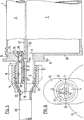
- the double discharge cartridge 1 has two storage cylinders 2 and 3, the cross-sectional areas of the storage cylinders in the present example being in a ratio of 10 to 1.
- the outlet openings 4 and 5 of the cylinders 2 and 3 are approximately the same size, ie they have approximately the same light width. Since the discharge channels in previously known double cartridges can also hold approximately the same volume, it takes much longer after the closure has been removed for this volume to be filled up from the small cartridge and thus much more mass comes in from the large cartridge during this time the mixer, whereby the mixing ratio of the two components is not exact.
- the two mouths of the discharge channels are shown and it can be seen that the Outlet mouth 4 of the channel of the large storage cylinder 2 is unchanged and corresponds to the light width of the outlet opening of this cylinder, while the mouth 6 has a cross section which corresponds to a tenth of the cross section of the large storage cylinder. It is possible to spray outlet openings or discharge channels with these two diameters directly, but this leads to shrinkage and other problems, especially in the case of high mixing ratios as a result of large material accumulations.
- the central wall 10 of the transition piece which emerges from the union of the two supply cylinder walls 46 and 47, protrudes beyond the cylindrical wall 11 with the thread 12 and is somewhat tapered. It can be clearly seen from FIGS. 1 or 3 that the two separate walls only unite after the closure region, ie above the two closure parts on the closure 32, in order to produce the middle wall 10. This prevents diffusion of the various components before mixing.
- the outer wall 11 of the transition piece does not open directly on the end faces 13 and 14 of the supply cylinder but in a flange 15 which is connected to the Front of the storage cylinder is connected.
- the flange and the transition structure are adaptation parts to the discharge devices.
- a union nut 19 is also drawn, which, among other things, attaches the mixer tube 20 to the transition piece.
- the mixer tube 20 is known per se and can, for example, contain helical elements in order to achieve thorough mixing of the components.
- the ratio of the light widths, i.e. the mouths 4 and 6 of the discharge channels is determined by an insert 21 which is inserted in the outlet opening 5 of the smaller storage cylinder 3.
- the outlet opening 4 of the larger cylinder does not contain such an insert because it can be used as a reference opening each time.
- the insert extends over the entire length of the transition piece and ends at the top with its tapered end wall 22 flush with the middle wall 10 and, at its other end on the cylinder side, on its outer wall 23 adapted to the inner wall of the transition piece, has a shoulder 24 which connects the inner wall 25 engages behind the end face 14 of the smaller storage cylinder, whereby the insert is secured.
- the lower part of the insert, at the shoulder 24, has a slot 26 in order to achieve a resilient effect.
- the side 27 of the insert facing the middle wall 10 has two shoulders 28 and 29, the second shoulder 29 on the supply cylinder side resting on a corresponding shoulder 30.
- the two shoulders 30 and 44 are formed by the top of flange 15, see FIG
- the insert 21 has in its center a cylindrical insert channel 31 whose cross-sectional ratio to the discharge channel of the larger supply cylinder is the same as the ratio of the cross-section of the smaller one Storage cylinder to the larger one.
- the two openings are closed by a closure 32, the openings being closed at the level of the inner walls of the end faces of the storage cylinders.
- the closure 32 consists of a rod-shaped part 33, the lower, cylindrical end 36 of which is adapted to the insert channel 31, and of a pin part 34 which is adapted to the discharge channel or the outlet opening 4 of the larger cylinder 2.
- the lowest part of the pin 34 has a cavity 38 in order to avoid material accumulation.
- the rod-shaped part 33 and the pin part 34 are closed at the top by a shoulder 39 or collar 40, these two parts being supported on the upper end of the outer wall 11 of the transition piece in the inserted state.
- a shoulder 39 or collar 40 Above the shoulder or collar there is a rib 45 on which the union nut 19 acts in order to press the closure.
- the shoulder 39 runs in a corresponding groove 41 in the beveled end face 22 of the insert. Both closure parts are connected to one another via a head 35 and the entire closure is injection-molded in one piece.
- both the rod-shaped part 33 and the pin part 34 can be advantageous or necessary to provide both the rod-shaped part 33 and the pin part 34 with a sealing lip 17 or 18 at the top.
- the inner wall 42 of the pin part 34 which comes to rest along the middle wall 10, has a shoulder 43 which can be supported on the corresponding shoulder 44 of the flange 15.
- the specified measures can ensure a secure and firm closure be guaranteed.
- the mixer tube 20 is fastened to the transition piece by means of the union nut 19 and the double cartridge is ready for dispensing in the correct mixing ratio, as shown in FIG. 5, without the material having to be thrown away.
- the same length of the discharge channels on the one hand and the storage cylinder on the other hand was assumed, so that their cross-sectional areas were compared.
- the volume of the discharge channels must be designed in relation to the volume of the assigned supply cylinder.
Landscapes
- Engineering & Computer Science (AREA)
- Mechanical Engineering (AREA)
- Physics & Mathematics (AREA)
- Geometry (AREA)
- Package Specialized In Special Use (AREA)
- Containers And Packaging Bodies Having A Special Means To Remove Contents (AREA)
Applications Claiming Priority (2)
| Application Number | Priority Date | Filing Date | Title |
|---|---|---|---|
| CH2426/90A CH681146A5 (fr) | 1990-07-20 | 1990-07-20 | |
| CH2426/90 | 1990-07-20 |
Publications (2)
| Publication Number | Publication Date |
|---|---|
| EP0467830A1 true EP0467830A1 (fr) | 1992-01-22 |
| EP0467830B1 EP0467830B1 (fr) | 1996-05-15 |
Family
ID=4233535
Family Applications (1)
| Application Number | Title | Priority Date | Filing Date |
|---|---|---|---|
| EP91810512A Expired - Lifetime EP0467830B1 (fr) | 1990-07-20 | 1991-07-01 | Cartouche à distribution multiple pour pâtes constituées par plusieurs composants |
Country Status (5)
| Country | Link |
|---|---|
| US (1) | US5228599A (fr) |
| EP (1) | EP0467830B1 (fr) |
| JP (1) | JP2952529B2 (fr) |
| CH (1) | CH681146A5 (fr) |
| DE (1) | DE59107802D1 (fr) |
Cited By (5)
| Publication number | Priority date | Publication date | Assignee | Title |
|---|---|---|---|---|
| EP0615922A1 (fr) * | 1993-03-15 | 1994-09-21 | Wilhelm A. Keller | Cartouche multiple et assemblage |
| EP0730913A1 (fr) * | 1995-03-07 | 1996-09-11 | Wilhelm A. Keller | Dispositif de fixation à bayonnette pour attacher un accessoire à une cartouche à composants multiples ou dispositif distributeur |
| BE1020815A3 (nl) * | 2012-07-04 | 2014-05-06 | Evs Polyservice Bvba | Werkwijze en inrichting voor het aanbrengen van polyurethaanschuim in een spouw. |
| EP3090962A1 (fr) * | 2015-05-06 | 2016-11-09 | Tomil s.r.o. | Distributeur de produit de nettoyage |
| US9914148B2 (en) | 2014-07-15 | 2018-03-13 | Sulzer Mixpac Ag | Multicomponent dispenser |
Families Citing this family (37)
| Publication number | Priority date | Publication date | Assignee | Title |
|---|---|---|---|---|
| DE59207545D1 (de) * | 1992-07-17 | 1997-01-02 | Wilhelm A Keller | Austragkartusche |
| EP0600138B1 (fr) * | 1992-11-30 | 1997-04-16 | Wilhelm A. Keller | Cartouche avec au moins un cylindre de stockage et un mélangeur |
| US5413253A (en) * | 1993-12-06 | 1995-05-09 | Coltene/Whaledent, Inc. | Static mixer |
| US5441175A (en) * | 1994-05-23 | 1995-08-15 | Jacobsen; Kenneth H. | Universal tool for twin cartridge material systems |
| EP0723807B1 (fr) | 1995-01-16 | 2001-09-19 | Wilhelm A. Keller | Mélangeur et dispositif de distribution pour plusieurs composants ainsi que procédé de connexion alignée du mélangeur avec le dispositif de distribution pour plusieurs composants |
| US5609271A (en) * | 1995-01-25 | 1997-03-11 | Wilhelm A. Keller | Mixer and multiple component dispensing device assembly and method for the aligned connection of the mixer to the multiple component dispensing device |
| US5918772A (en) | 1995-03-13 | 1999-07-06 | Wilhelm A. Keller | Bayonet fastening device for the attachment of an accessory to a multiple component cartridge or dispensing device |
| US6769574B1 (en) | 1995-03-13 | 2004-08-03 | Mixpac Systems Ag | Dispensing assembly having coded attachment of an accessory to a multiple component cartridge or dispensing device using differently sized inlets and outlets |
| DE69605642T2 (de) * | 1996-02-21 | 2000-05-11 | Wilhelm A. Keller | Mittel zur richtigen Befestigung einer Mehrkomponentenkartusche auf einem Austraggerät |
| US6062492A (en) | 1998-05-15 | 2000-05-16 | Sealant Equipment & Engineering, Inc. | Viscous material dispense system |
| DE29912890U1 (de) * | 1999-07-23 | 1999-09-16 | Prestele, Eugen, 86179 Augsburg | Zweikomponentenkartusche |
| JP2004500286A (ja) * | 1999-12-17 | 2004-01-08 | ジカ アクチェンゲゼルシャフト,フォルム.カスパービンクラー ウント コンパニー | 多室チューブ状袋から物質を採取するためのアダプタ、配置構成および方法、アダプタの使用、ならびにチューブ状袋包装 |
| DE10254409A1 (de) * | 2002-11-21 | 2004-06-03 | Ernst Mühlbauer Gmbh & Co. Kg | Vorrichtung zum Mischen und Ausbringen von Mehrkomponentenmassen |
| DE10304611A1 (de) * | 2003-02-05 | 2004-08-19 | Basf Ag | Verfahren und Vorrichtung zur Zertrennung pastöser Formmassen |
| EP1628706A1 (fr) * | 2003-06-03 | 2006-03-01 | Mixpac Systems AG | Dispositif pour raccorder une tubule a un melangeur |
| WO2005077766A1 (fr) * | 2004-02-13 | 2005-08-25 | Henkel Kommanditgesellschaft Auf Aktien | Flacon distributeur pour au moins deux liquides a principe actif |
| US7617950B2 (en) * | 2004-05-24 | 2009-11-17 | Colgate-Palmolive Company | Controlling flow from multi-chamber containers |
| USD534773S1 (en) * | 2004-10-04 | 2007-01-09 | Polymer Systems Co., Ltd. | Head for a caulking apparatus |
| USD530165S1 (en) * | 2004-10-13 | 2006-10-17 | Polymer Systems Co., Ltd. | Head for a caulking apparatus |
| US20100108709A1 (en) * | 2004-12-30 | 2010-05-06 | Plas-Pak Industries | Cartridge delivery system utilizing film bags |
| US9517488B2 (en) | 2004-12-30 | 2016-12-13 | Plas-Pak Industries, Inc. | Component delivery system utilizing film bags |
| GB0504990D0 (en) * | 2005-03-10 | 2005-04-20 | Cox Ltd | Dispensing appliance and cartridge therefor |
| AU2008229561B2 (en) | 2007-03-19 | 2013-05-16 | Sulzer Mixpac Ag | Dispensing assembly having removably attachable accessories |
| JP5172185B2 (ja) | 2007-03-22 | 2013-03-27 | 株式会社ジーシー | ミキシングチップ |
| JP4987661B2 (ja) * | 2007-10-19 | 2012-07-25 | 東洋製罐株式会社 | 注出部材 |
| JP5172514B2 (ja) | 2008-07-15 | 2013-03-27 | 株式会社ジーシー | ミキシングチップ |
| CA2686581C (fr) * | 2009-02-11 | 2017-06-27 | Sulzer Mixpac Ag | Piece intermediaire pour raccorder un contenant de stockage a un melangeur statique |
| ES2836798T3 (es) * | 2010-04-28 | 2021-06-28 | Ips Adhesives Llc | Aparato para mezclar y dispensar múltiples componentes fluidos |
| GB201012094D0 (en) * | 2010-07-19 | 2010-09-01 | 2K Polymer Systems Ltd | Multi-component dispenser |
| BR112013010171B1 (pt) * | 2010-10-26 | 2020-12-22 | 3lmed GmbH | Combinação que consiste em um cartucho duplo e um misturador para o uso do mesmo |
| US8960501B2 (en) * | 2012-10-23 | 2015-02-24 | Nordson Corporation | Dispensing assembly and method for dispensing a mixed fluid |
| US9138772B2 (en) | 2012-10-31 | 2015-09-22 | Nordson Corporation | Dispensing assembly and method using snap engagement of a mixer and a cartridge |
| JP5973365B2 (ja) | 2013-03-01 | 2016-08-23 | 株式会社ジーシー | 歯科用ミキサー |
| US9757763B2 (en) * | 2013-10-31 | 2017-09-12 | Nordson Corporation | Side by side cartridge assemblies and related methods |
| US10099838B2 (en) * | 2015-04-13 | 2018-10-16 | Nordson Corporation | Fluid cartridge system and method of using a fluid cartridge system |
| US10281074B2 (en) * | 2016-01-14 | 2019-05-07 | Nordson Corporation | Adapters for connecting a separated-outlet fluid cartridge to a single-inlet mixer, and related methods |
| US10369589B2 (en) * | 2017-05-12 | 2019-08-06 | Alan Dale | Nozzle adapter |
Citations (3)
| Publication number | Priority date | Publication date | Assignee | Title |
|---|---|---|---|---|
| EP0105181A2 (fr) * | 1982-09-07 | 1984-04-11 | Liquid Control International Co. | Dispositif pour la distribution des mélanges fluides |
| EP0302819A2 (fr) * | 1987-07-30 | 1989-02-08 | HILTI Aktiengesellschaft | Magasin de cartouche pour substances coulantes |
| EP0340493A1 (fr) * | 1988-04-29 | 1989-11-08 | Maderag Ag | Récipient pour produits pateux |
Family Cites Families (4)
| Publication number | Priority date | Publication date | Assignee | Title |
|---|---|---|---|---|
| DE3317106A1 (de) * | 1983-05-10 | 1984-11-15 | Rotpunkt Dr. Anso Zimmermann, 6434 Niederaula | Eine geschlossene schnaupe bildender ausgiesser sowie verfahren zur herstellung eines damit versehenen behaelters |
| EP0294672B1 (fr) * | 1987-06-10 | 1992-08-12 | Wilhelm A. Keller | Cartouche double pour mélange à deux composants |
| DE8900469U1 (de) * | 1989-01-17 | 1990-05-23 | Espe Stiftung & Co Produktions- und Vertriebs KG, 8031 Seefeld | Vorrichtung zum Mischen und Ausbringen pastöser Massen |
| US4974756A (en) * | 1989-07-14 | 1990-12-04 | Minnesota Mining And Manufacturing Company | Double barrel dispensing container and cap therefor |
-
1990
- 1990-07-20 CH CH2426/90A patent/CH681146A5/de not_active IP Right Cessation
-
1991
- 1991-07-01 EP EP91810512A patent/EP0467830B1/fr not_active Expired - Lifetime
- 1991-07-01 DE DE59107802T patent/DE59107802D1/de not_active Expired - Lifetime
- 1991-07-17 US US07/731,458 patent/US5228599A/en not_active Expired - Lifetime
- 1991-07-20 JP JP3180032A patent/JP2952529B2/ja not_active Expired - Lifetime
Patent Citations (3)
| Publication number | Priority date | Publication date | Assignee | Title |
|---|---|---|---|---|
| EP0105181A2 (fr) * | 1982-09-07 | 1984-04-11 | Liquid Control International Co. | Dispositif pour la distribution des mélanges fluides |
| EP0302819A2 (fr) * | 1987-07-30 | 1989-02-08 | HILTI Aktiengesellschaft | Magasin de cartouche pour substances coulantes |
| EP0340493A1 (fr) * | 1988-04-29 | 1989-11-08 | Maderag Ag | Récipient pour produits pateux |
Cited By (8)
| Publication number | Priority date | Publication date | Assignee | Title |
|---|---|---|---|---|
| EP0615922A1 (fr) * | 1993-03-15 | 1994-09-21 | Wilhelm A. Keller | Cartouche multiple et assemblage |
| US5462205A (en) * | 1993-03-15 | 1995-10-31 | Keller; Wilhelm A. | Pluggable multiple cartridge |
| EP0730913A1 (fr) * | 1995-03-07 | 1996-09-11 | Wilhelm A. Keller | Dispositif de fixation à bayonnette pour attacher un accessoire à une cartouche à composants multiples ou dispositif distributeur |
| EP1125641A1 (fr) * | 1995-03-07 | 2001-08-22 | Wilhelm A. Keller | Dispositif de fixation à bayonnette pour attacher un accessoire à une cartouche à composants multiples ou dispositif distributeur |
| BE1020815A3 (nl) * | 2012-07-04 | 2014-05-06 | Evs Polyservice Bvba | Werkwijze en inrichting voor het aanbrengen van polyurethaanschuim in een spouw. |
| US9914148B2 (en) | 2014-07-15 | 2018-03-13 | Sulzer Mixpac Ag | Multicomponent dispenser |
| US10293362B2 (en) | 2014-07-15 | 2019-05-21 | Sulzer Mixpac Ag | Multicomponent dispenser |
| EP3090962A1 (fr) * | 2015-05-06 | 2016-11-09 | Tomil s.r.o. | Distributeur de produit de nettoyage |
Also Published As
| Publication number | Publication date |
|---|---|
| US5228599A (en) | 1993-07-20 |
| DE59107802D1 (de) | 1996-06-20 |
| JP2952529B2 (ja) | 1999-09-27 |
| EP0467830B1 (fr) | 1996-05-15 |
| CH681146A5 (fr) | 1993-01-29 |
| JPH04239477A (ja) | 1992-08-27 |
Similar Documents
| Publication | Publication Date | Title |
|---|---|---|
| EP0467830A1 (fr) | Cartouche à distribution multiple pour pâtes constituées par plusieurs composants | |
| EP0378806B1 (fr) | Dispositif de mélange et de distribution de produits pâteux | |
| DE4412261C2 (de) | Vorrichtung zum Zusammenführen wenigstens zweier Fließmedien | |
| EP0664153A1 (fr) | Mélangeur | |
| EP1402940A2 (fr) | Mélangeur pour pâtes à plusieurs constituants | |
| EP0294672A1 (fr) | Cartouche double pour mélange à deux composants | |
| CH670580A5 (fr) | ||
| DE3129142A1 (de) | Ausgabegeraet fuer ein produkt von hoher viskositaet | |
| CH674717A5 (en) | Mixing device for at least two cartridges - has mixing head, semi-outer welded shells, supplies, strips or screw conveyor | |
| EP0443519A2 (fr) | Dispositif de distribution de fluide | |
| DE19744746A1 (de) | Vorrichtung zum Lagern, Auspressen und Dosieren von Zweikomponenten-Zusammensetzungen | |
| DE29709383U1 (de) | Behälter für pastöse Massen | |
| DE3420323A1 (de) | Abgabevorrichtung fuer meherere stroemungsfaehige materialkomponenten | |
| DE4224497A1 (de) | Mundstück für Auspressgeräte, die dem Abgeben von Zweikomponentenmassen dienen | |
| DE3233744C2 (de) | Verfahren zum Mischen eines kunststoffhaltigen Spritzbetons und Düsenmischkörper zur Durchführung des Verfahrens | |
| EP0019029B1 (fr) | Installation pour prélever simultanément le contenu de récipients en forme de boîtes remplis de masses pâteuses, en particulier de matières d'étanchéité ou de mastic, et de durcisseurs | |
| EP2868392A1 (fr) | Douille, dispositif d'extraction comprenant la douille et procédé | |
| DE10022160B4 (de) | Applikator | |
| DE69502862T2 (de) | Ausgiesstülle, Ausgiesstülle und Verschlussanordnung sowie Behälteranordnung | |
| CH390478A (de) | Vorrichtung zum gleichzeitigen Abgeben von zwei pastenartigen Substanzen | |
| DE1185981B (de) | Verfahren und Fuellduese zum Fuellen von Quetschtuben mit verschiedenfarbigen pastenartigen Stoffen | |
| EP3971106B1 (fr) | Cartouche à deux composants | |
| CH619902A5 (en) | Tube | |
| DE1957097A1 (de) | Staukopf fuer Schneckenpressen zum Extrudieren von thermoplastischem Kunststoff | |
| EP4605197A1 (fr) | Tête d'impression en béton 3d |
Legal Events
| Date | Code | Title | Description |
|---|---|---|---|
| PUAI | Public reference made under article 153(3) epc to a published international application that has entered the european phase |
Free format text: ORIGINAL CODE: 0009012 |
|
| AK | Designated contracting states |
Kind code of ref document: A1 Designated state(s): CH DE FR GB IT LI |
|
| 17P | Request for examination filed |
Effective date: 19920716 |
|
| 17Q | First examination report despatched |
Effective date: 19931207 |
|
| GRAH | Despatch of communication of intention to grant a patent |
Free format text: ORIGINAL CODE: EPIDOS IGRA |
|
| GRAA | (expected) grant |
Free format text: ORIGINAL CODE: 0009210 |
|
| ITF | It: translation for a ep patent filed | ||
| AK | Designated contracting states |
Kind code of ref document: B1 Designated state(s): CH DE FR GB IT LI |
|
| REG | Reference to a national code |
Ref country code: CH Ref legal event code: NV Representative=s name: AMMANN PATENTANWAELTE AG BERN |
|
| REF | Corresponds to: |
Ref document number: 59107802 Country of ref document: DE Date of ref document: 19960620 |
|
| GBT | Gb: translation of ep patent filed (gb section 77(6)(a)/1977) |
Effective date: 19960814 |
|
| ET | Fr: translation filed | ||
| PLBE | No opposition filed within time limit |
Free format text: ORIGINAL CODE: 0009261 |
|
| STAA | Information on the status of an ep patent application or granted ep patent |
Free format text: STATUS: NO OPPOSITION FILED WITHIN TIME LIMIT |
|
| 26N | No opposition filed | ||
| REG | Reference to a national code |
Ref country code: GB Ref legal event code: IF02 |
|
| REG | Reference to a national code |
Ref country code: GB Ref legal event code: 732E |
|
| REG | Reference to a national code |
Ref country code: FR Ref legal event code: TP |
|
| REG | Reference to a national code |
Ref country code: CH Ref legal event code: PUE Owner name: MIXPAC SYSTEMS AG Free format text: KELLER, WILHELM A.#OBSTGARTENWEG 9#CH-6402 MERLISCHACHEN (CH) -TRANSFER TO- MIXPAC SYSTEMS AG#GRUNDSTRASSE 12#6343 ROTKREUZ (CH) |
|
| PGFP | Annual fee paid to national office [announced via postgrant information from national office to epo] |
Ref country code: CH Payment date: 20100726 Year of fee payment: 20 |
|
| PGFP | Annual fee paid to national office [announced via postgrant information from national office to epo] |
Ref country code: DE Payment date: 20100723 Year of fee payment: 20 Ref country code: FR Payment date: 20100805 Year of fee payment: 20 Ref country code: IT Payment date: 20100726 Year of fee payment: 20 |
|
| PGFP | Annual fee paid to national office [announced via postgrant information from national office to epo] |
Ref country code: GB Payment date: 20100722 Year of fee payment: 20 |
|
| REG | Reference to a national code |
Ref country code: DE Ref legal event code: R071 Ref document number: 59107802 Country of ref document: DE |
|
| REG | Reference to a national code |
Ref country code: DE Ref legal event code: R071 Ref document number: 59107802 Country of ref document: DE |
|
| REG | Reference to a national code |
Ref country code: CH Ref legal event code: PL |
|
| REG | Reference to a national code |
Ref country code: GB Ref legal event code: PE20 Expiry date: 20110630 |
|
| PG25 | Lapsed in a contracting state [announced via postgrant information from national office to epo] |
Ref country code: GB Free format text: LAPSE BECAUSE OF EXPIRATION OF PROTECTION Effective date: 20110630 |
|
| PG25 | Lapsed in a contracting state [announced via postgrant information from national office to epo] |
Ref country code: DE Free format text: LAPSE BECAUSE OF EXPIRATION OF PROTECTION Effective date: 20110702 |